Note: Descriptions are shown in the official language in which they were submitted.
CA 02372976 2002-02-25
Title of the invention
LIGHT SOURCE HAVING PLURAL LASER DIODE MODULES
Field of the Invention
The present invention generally relates to a high power light source.
More specifically, the present invention is directed to a light source
comprising
a plurality of laser diode modules having high optical power and arranged in
high density.
Description of the Related Art
Normally, laser diode modules are employed as signal light sources of
optical fiber communications, especially, signal light sources of main trunk
systems / CATV systems, and light-excitation light sources of fiber
amplifiers.
In such a laser diode module, a Pettier-effect element is built therein, and
various optical components and various electronic components are arranged on
a metal substrate mounted on the Pettier-effect element in order to realize
high
optical power and stable operations of the laser diode module. The optical
components are a laser diode chip, a photodiode chip, a lens, and the like
whereas; the electronic components are a thermistor element, an inductor, a
resistor, and the like.
It should be noted that the above-explained Pettier-effect element is a
thermocouple semiconductor. In the case that the Pettier-effect element is
made
from a p-type semiconductor, when a DC current is supplied to the Pettier-
effect
element, heat is moved along the current flowing direction. In the case that
the
Pettier-effect element is made from an n-type semiconductor, when a DC
current is supplied thereto, heat is moved along a direction opposite to the
current flowing direction, so that a temperature difference is produced
between
CA 02372976 2002-02-25
both ends of the thermocouple semiconductor. In a cooling system using such a
Pettier-effect element, a low-temperature side thereof is used for cooling,
and a
high-temperature side thereof is used for heat dissipation, while utilizing
the
above-explained temperature difference.
In the laser diode module, a temperature of the above-explained laser
diode chip is detected by the thermistor element positioned in the vicinity of
the
laser diode chip. The laser diode module includes the following structure
which
is capable of keeping the temperature of the laser diode chip constant. That
is,
the thus detected value of the temperature is fed back so as to drive the
Pettier-
effect element, so that the entire metal substrate where the laser diode chip
is
arranged is cooled.
Fig. 5 depicts a conventional laser diode module. Fig. 5 is a sectional
view for schematically showing the conventional laser diode module. As
shown in Fig. 5, the laser diode module includes a mount 113 for mounting
thereon both a laser diode chip 111 and a heat sink 112, a chip carrier 115
for
mounting thereon a monitoring photodiode chip 114, a lens holder 116, a metal
substrate 1 l0a for mounting thereon a resistor, an inductor, and a circuit
board
(not shown); and a Pettier-effect element 117. The Pettier-effect element 117
is
fixed on a heat dissipating plate 118 of a package by metal solder. It should
also be noted that ceramics plates 119A and 119B are arranged on upper and
lower portions of a Pettier-effect element 117.
Fig. 6 is a sectional view for showing the laser diode module, taken along
a line A to A' in Fig. 5. As shown in Fig. 6, as an essential portion of the
laser
diode module, a thermistor 121 and the laser diode chip 111 are mounted on the
heat sink 112. As a metal solder used to adhere the Pettier-effect element 117
to the metal substrate 110a, soft solder 122 is employed in order to relax a
thermal expansion difference between the two members.
2
CA 02372976 2002-02-25
The above-explained metal substrate is in general made of a single
material such as copper tungsten (CuW: weight distribution ratio of copper is
10% to 30%). When the metal substrate is adhered to the Pettier-effect
element,
low-temperature soft solder such as indium tin (InSn) is employed so as to
relax
the thermal expansion difference between the two materials.
However, recently, more severe requests are made with respect to both
the cooling capability of the laser diode module, and the temperature
environmental reliability (namely, capability of maintaining normal functions
under the condition even when temperature varies).
At first, in order to improve the cooling capability, the size of the Peltier-
effect element should be made large, and also the metal substrate mounted on
the upper portion thereof must be made from the high heat transfer material.
Since the temperature adjusting time (namely, time duration until target
temperature is reached) is reduced due to improvements in the cooling
capability of the Pettier-effect element, the temperature stress given to the
metal
substrate mounted on the Pettier-effect element is also increased. As a
result,
the adverse influence given by the difference of the heat expansion
coefficients
between the Pettier-effect element and the metal substrate is increased. As a
result, there is such a problem that cracks and exfoliation will occur,
because
the soft solder used to adhere the both members is slid. Moreover, since the
soldering creep phenomenon which is specific to the soft solder becomes
apparent, such a low-temperature hard solder as bismuth tin (BiSn) must be
employed as the solder for adhering the Pettier-effect element to the metal
substrate.
To solve the above-explained problem, Japanese Patent Provisional
Publication No: Hei 10-200208 discloses a semiconductor laser module
including a metal substrate made of two different kinds of metal materials.
Fig.
3
CA 02372976 2002-02-25
7 schematically shows a conceptional structure of the semiconductor laser
module. As shown in Fig. 7A, the semiconductor laser module is manufactured
as follows: a metal substrate 210 is adhered to a Pettier-effect element 207
with
ceramics boards 209A and 2098 mounted on upper and lower surfaces thereof
by using hard solder 212. An LD chip 201 and a thermistor 211 are mounted on
the metal substrate 210 through a heat sink 202 and a sub-mount 203 together
with a lens of an optical system. The thermistor 211 is employed so as to keep
the temperature of the LD chip 201 constant.
The metal substrate 210 is adhered onto the upper surface of the Peltier-
effect element 207 in such manner that a heat flow derived from the LD chip
201 directed to the Pettier-effect element 207 is in perpendicular thereto. In
particular, the metal substrate 210 is formed in such a manner that a first
metal
member 213 is arranged at a center portion of the substrate including a
portion
located directly below the LD 201, and a second metal member 214 is arranged
so as to surround the first metal member. Furthermore, as depicted in Fig. 7B,
the metal substrate 210 is manufactured in such a manner that the first metal
member 213 is formed by such a metal member having a large heat
conductivity, whereas the second metal member 214 is made of such a metal
member having a heat expansion coefficient smaller than that of the first
metal
member 213.
In other words, it is expected that since the above-explained metal
substrate 210 is employed, the heat expansion of the entire metal substrate
can
be reduced, the heat condution thereof can be improved so as to increase the
cooling performance. At the same time, it is expected that reliability of the
Pettier-effect element is improved.
It should also be noted that in general, a plurality of laser diode modules
functioning as a light output source are mounted on either the light-
excitation
CA 02372976 2002-02-25
light source or the optical-signal light source. A laser diode module is
combined with other optical components so as to be used in an optical
amplifier.
In accordance with the above-explained prior art, it is so expected that the
cooling performance of the Pettier-effect element may be improved and also the
reliability of the Pettier-effect element may be increased in each of the
laser
diode modules. However, in the case that the respective laser diode modules
output higher optical power, and also a large number of such high-power laser
diode modules are arranged in high density to be driven, the resulting heat
generated from the high-power laser diode modules arranged in high density
could not be properly treated by merely increasing the heat conducting
property
of the metal substrate which is arranged between the chip and the Pettier-
effect
element, or by merely reducing the difference in the heat expansion
coefficient.
As a result, there is another problem that the functions of the laser diode
module
would be damaged.
More specifically, since the size of each of these laser diode modules per
se is small, but a high density heat generator, when a plurality of these
laser
diode modules are required to be mounted as either the light-excitation light
source or the optical-signal light source, it is practically difficult to
dissipate
heat from the laser diode modules. On the other hand, further improvements in
high light output power axe needed in either the light-excitation light source
or
the light-signal light source. In the conventional method, there is a
limitation in
the cooling effect achieved by the Pettier-effect element of the laser diode
module. As a result, the laser diode modules could be used only under such a
condition that the performance of the semiconductor element remains far below
100 %.
Furthermore, even when the optical power of the laser diode module is
CA 02372976 2002-02-25
increased in response to needs of the market, there is a strong need that the
power consumption caused by excitation of both the Pettier-effect element and
the semiconductor element is required to be kept lower than that of the
conventional art. Therefore, the heat dissipation property within the light
source may become very important.
In addition to the laser diode module, another request is made of treating
the heat generated by the laser diode module control board equipped with
another heat generating element (for example, CPU) for controlling the laser
diode module.
As previously explained, developments of either a light-excitation light
source or an optical-signal light source, which is mounted on a heat sink
having
excellent heat dissipation, are strongly expected.
SUMMARY OF THE INVENTION
There is provided a light source having laser diode modules of the
invention comprising a plurality of laser diode modules being arranged in high
density, each of said laser diode modules having an optical power of at least
300 mW. More specifically, in a light source having laser diode modules of the
invention, the light source comprises:
a plurality of laser diode modules, each of which includes a metal substrate
and a Pettier-effect element thermally connected to said metal substrate, said
metal substrate mounting thereon a laser diode chip and an optical appliance;
and
a mounting portion comprising one plate type heat pipe, on which said
plurality of laser diode modules are mounted.
BRIEF DESCRIPTION OF THE DRAWINGS
CA 02372976 2002-02-25
For a better understanding of the present invention, reference is made of a
detailed description to be read in conjunction with the accompanying drawings,
in which:
Fig. 1 is a diagram for schematically showing one structural example of
each of laser diode modules which constitute a light source according to the
present invention;
Figs. 2A and 2B are diagrams for illustratively showing a light source
having plural laser diode modules according to an embodiment of the present
invention;
Figs. 3A and 3B are diagrams for illustratively indicating a light source
having plural laser diode modules according to another embodiment of the
present invention;
Fig. 4 is a top view for illustratively representing a light source having
plural laser diode modules according to further another embodiment of the
present invention;
Fig. 5 is a diagram for indicating the conventional laser diode module;
Fig. 6 is a sectional view of the laser diode module, taken along a line A
to A' of Fig. 5; and
Figs. 7A and 7B are diagrams for illustratively indicating the
semiconductor laser module equipped with the metal substrate comprising two
kinds of metal materials.
DETAILED DESCRIPTION OF THE PREFERRED EMBODIMENTS
With Reference to drawings, various embodiments of a light source
having laser diode modules of the present invention will be described in
detail.
An object of the present invention is to provide a light source including a
plurality of laser diode modules arranged in high density, capable of
outputting
CA 02372976 2002-02-25
high optical power.
The inventors of the present invention have made an intensive study to
solve the above-explained problems of the prior art, and found the followings.
When a heat pipe having a heat conductivity which is at least about 20 times
larger than a heat conductivity of monocrystal diamond is connected to a
Peltier-effect element, a risk that the Peltier-effect element is destroyed
could be
considerably reduced. The heat pipe connecting method has been
conventionally disliked and refused by users due to the following reasons. It
has been thought that since a fluid called as a "working fluid" is contained
in
the heat pipe, an adverse influence, which is caused by leakage and humidity
of
this working fluid, may be supposed to occur. Therefore, such a working fluid
is not wanted to be used in a highly precise appliance such as a laser diode
module. However, the inventors could come to recognize such a fact that the
resulting laser diode modules can output high optical power, and also these
laser diode modules can be arranged in high density by using such a heat pipe.
In addition, the inventors could have the following findings. When a heat
pipe, more specifically, a heat absorbing portion of a plate type heat pipe is
thermally connected to a Pettier-effect element provided in each of laser
diode
modules, even if a large number of laser diode modules each having high
optical output power are arranged in high density, then the respective laser
diode modules can be cooled in not-comparable cooling degrees with respect to
the conventional cooling performance. The laser diode modules are equipped
with a metal substrate and the Pettier-effect elements thermally connected to
this metal substrate on which a laser diode chip and an optical appliance are
mounted. As a consequence, it is possible to provide a light source having a
plurality of laser diode modules with high reliability and capable of
outputting
high optical power.
CA 02372976 2002-02-25
Moreover, a mounting portion on which the above-explained plural laser
diode modules are mounted is manufactured by one plate type heat pipe, and
also, round type heat pipe portions are extended along two directions from a
rectangular main body portion of this plate type heat pipe, and in addition
heat
dissipating fins attached to the round type heat pipe portions. As a
consequence, since heat may be transferred in a predetermined direction, a
thickness of a light source can be made thin, and furthermore, a wider contact
surface of the plate type heat pipe can be utilized. Therefore, a mounting
direction and a mounting position on the mounting portion of a case on which a
plurality of laser diode modules are mounted can be freely selected, resulting
in
increasing of a design freedom.
One embodiment of a light source having laser diode modules of the
invention comprises a plurality of laser diode modules being arranged in high
density, each of the laser diode modules having an optical power of at least
300
mW. In other embodiment of the light source having laser diode modules of the
invention, the light source comprises: a plurality of laser diode modules,
each of
which includes a metal substrate and a Pettier-effect element thermally
connected to the metal substrate, the metal substrate mounting thereon a laser
diode chip and an optical appliance; and a mounting portion comprising one
plate type heat pipe, on which the plurality of laser diode modules are
mounted.
In addition, in other embodiment of the light source having laser diode
modules of the invention, a heat absorbing portion of the plate type heat pipe
is
thermally connected to the Pettier-effect element. In addition, a laser diode
module control board is thermally connected to a surface of the plate type
heat
pipe functioning as the mounting portion, the surface of the plate type heat
pipe
being located opposite to a surface thereof on which the plurality of laser
diode
modules are mounted.
9
CA 02372976 2002-02-25
In addition, in other embodiment, the plate type heat pipe comprises a main
body portion having a rectangular shape, and at least one round type heat pipe
portion which is extended from the rectangular main body portion and is
integrally formed with the rectangular main body portion as a single member.
The main body portion comprises a hollow construction having a cavity portion,
the cavity portion of said main body portion being communicated with internal
portions of the round type heat pipes.
In other embodiment, the round type heat pipe portions may be extended
from the rectangular main body portions in one direction. The round type heat
pipe portions may be extended from the rectangular main body portions along
plural directions. Positions and directions to be arranged of the plural laser
diode modules are selected in free choice. The first group of the round type
heat pipe portions may be extended from the rectangular main body portions in
one direction, and second group of the round type heat pipe portions may be
extended from the rectangular main body portions in opposite direction to the
one direction. Number of the first and second group of the round type heat
pipe
portions may be the same. Number of the first and second group of the round
type heat pipe portions may be different from each other. In addition, in
other
embodiment, each of the round type heat portion may further includes heat
dissipating fins.
Fig. 1 is a schematic diagram for representing one structural example of
each of laser diode modules which constitute a light source of the present
invention. As depicted in Fig. 1, the laser diode module 10 includes a
semiconductor laser 1 l, a first lens 12, a second lens 13, a core-enlarged
fiber
14, and a hermetical case (i.e., hermetically sealed case) 20. The
semiconductor
laser l l is provided on a base 21 through a chip carrier 22, while keeping a
preselected interval with respect to the first lens 12. The base 21 is
arranged
to
CA 02372976 2002-02-25
above a Peltier-effect element 23. The Peltier-effect element 23 is provided
within the hermetical case 20, and is used to control temperatures. As to the
base 21, an essential portion thereof is made of copper, and a portion where
the
first lens 12 is mounted is made of a composite member made of stainless
steel.
A carrier 24 is fixed on the base 21 in such a manner that the carrier 24 is
located opposite to the first lens 12 with the chip carrier 22 sandwiched
therebetween. A photo diode 24a for monitoring is provided so as to face the
semiconductor laser 11 of the chip carrier 22.
The collimator lens 12b is held by a lens holder 12a in the first lens 12.
The lens holder 12a is fixed on the base 21 by welding. In the collimator lens
12b, an aspheric lens is employed in order to achieve a high coupling
efficiency.
As to the second lens 13, a spherical lens 13b, the upper and lower portions
of
which are cut out, is held by a lens holder 13a. The lens holder 13a is fixed
in
an insertion cylinder 20a (which will be explained later) of the hermetically
sealed case 20, while a position of the lens holder 13a is adjusted within a
plane
located perpendicular to an optical axis.
As to the core-enlarged fiber 14, a tip-sided portion whose core is
enlarged is obliquely polished and is inclined at an angle of 6 degrees with
respect to the optical axis, and also a polished surface of the core-enlarged
tip-
sided portion is coated by an anti-reflection coating treatment. Then, the tip-
sided portion is adhered inside a metal cylinder 15 so that this tip-sided
portion
of the core-enlarged fiber 14 may be protected. The metal cylinder 15 is fixed
at an optimum position of an adjusting member 16 by welding. The metal
cylinder 15 is positionally adjusted to the optimum position of the adjusting
member 16 in such a way that the metal cylinder 15 is slid in forward and
backward directions along the optical axis direction of the core-enlarged
fiber
14 within the adjusting member 16, and is rotated around the optical axis.
11
CA 02372976 2002-02-25
Figs. 2A and 2B are diagrams for illustratively depicting a light source
having laser diode modules, according to one embodiment of the present
invention. Fig. 2A is a sectional view for showing the light source having the
laser diode modules according to one embodiment, and Fig. 2B is an upper view
for representing the light source having the laser diode modules according to
one embodiment.
As illustrated in Fig. 2A, in this embodiment, a mounting portion 30 on
which a plurality of laser diode modules are mounted comprises a plate type
heat pipe. The plate type heat pipe functioning as the mounting portion 30 is
formed by such a metal having a superior heat transfer property such as
copper,
or aluminum. The plate type heat pipe is manufactured to be a hollow structure
having a hermetically sealed cavity portion 40. A working fluid, which is
adaptable to the material of the heat pipe, is filled into the cavity portion
40.
The laser diode module 10 is directly arranged on one surface (namely, heat
absorbing portion) of the plate type heat pipe. Since the wider rectangular
surface of the plate type heat pipe may be utilized, both the arranging
position
and the arranging direction of the laser diode module 10 may be freely
selected.
A heat sink 33 such as a heat dissipating fin is thermally connected to the
other
surface of the plate type heat pipe. Since the plate type heat pipe may be
directly employed as the mounting portion, the arranging density of the laser
diode module may be increased as much as possible by means of superior heat
transfer of the plate type heat pipe, as far as it can be physically arranged.
In general, a heat pipe is provided with a container having a hermetically
sealed cavity portion, and a heat transfer is carried out by way of both phase
transition and movement of a working fluid which is received in the cavity
portion. Although a portion of the heat is directly transferred through a
material
of the container which constitutes the heat pipe, a major portion of the heat
is
12
CA 02372976 2002-02-25
transferred by way of both the phase transition and the movement of the
working fluid.
On the heat absorption side of the heat pipe, on which a component to be
cooled is mounted, the working fluid is evaporated by receiving the heat
transferred through the material ofthe container which constitutes he heat
pipe,
and then, the vaporized working fluid is moved to the heat dissipation side of
the heat pipe. On the heat dissipation side, the vaporized working fluid is
cooled and returned back to the liquid phase state. The working fluid which
has
been returned to the liquid phase state is again moved to the heat absorption
side. A large amount of heat may be quickly moved by way of both the above-
mentioned phase transition and the movement of the working fluid.
Figs. 3A and 3B are diagrams for illustratively depicting a light source
having laser diode modules, according to another embodiment of the present
invention. Fig. 3A is a sectional view for showing the light source having the
laser diode modules according to this embodiment, and Fig. 3B is an upper view
for representing the light source having the laser diode modules according to
this embodiment. In the light source having the laser diode modules according
to this embodiment, a mounting portion comprises a main body portion 31 made
of a rectangular plate type heat pipe, and round type heat pipe portions 32.
The
round type heat pipe portions 32 are extended from the main body portion 3 l,
and are integrally formed with the main body portion 31 as a single member.
The main body portion 31 of the plate type heat pipe, which function as
the mounting portion, and the round type heat pipe portions 32 are integrally
formed as a single member by such a metal having a superior heat transfer
characteristic such as copper and aluminum. The main body portion comprises
a hollow construction having a cavity portion 40. The cavity portion 40 of the
main body portion is communicated with internal portions 41 of the round type
13
CA 02372976 2002-02-25
heat pipe portions. The laser diode module 10 is directly arranged on one
surface (namely, heat absorption portion) of the plate type heat pipe. Also,
in
this embodiment, since a wider rectangular surface of the plate type heat pipe
may be utilized, both the arranging position and arranging direction of the
laser
diode modules 10 may be freely selected. Heat dissipating fins 34 are attached
to the round type heat pipe portions 32. In this embodiment, the heat
generated
from a plurality of laser diode modules is firstly transferred to the main
body
portion of the plate type heat pipe on which the laser diode modules are
directly
mounted, and is further transferred to both the cavity portion of the main
body
portion and the round type heat pipe portions whose inner portions are
communicated with the cavity portion. Heat may be dissipated to a
predetermined position by way of the heat dissipating fins attached to the
round
type heat pipe portions.
As explained above, in addition, in this embodiment, the surface 42 of the
main body portion of the plate type heat pipe, which is located opposite to
the
surface 31 on which the laser diode modules 10 are mounted, may also be used
as the heat absorbing portion of the heat pipe. In other words, a laser diode
module control board or the like may be thermally connected to the surface.
The laser diode module control board controls the laser diode modules, and
mounts thereon other heat generation element (for instance, CPU, DSP (Digital
Signal Processor), FET(Field Effect Transistor). In this case, a proper heat
pipe
is selected by considering a maximum heat transfer amount of a heat pipe to be
used, the heat generating amount of the laser diode modules, and also the heat
generating amount of the laser diode module control board or the like. As a
result, the heat dissipation can be effectively carried out, and thus, the
functions
of the laser diode modules which are capable of outputting high optical power
and are arranged in high density can be sufficiently realized.
14
CA 02372976 2002-02-25
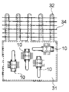
Fig. 4 is an upper view for illustratively showing a light source having
laser diode modules, according to another embodiment of the present invention.
In the light source having the laser diode modules according to this
embodiment, a mounting portion comprises a main body portion 31 of a
rectangular plate type heat pipe, and two sets of round type heat pipe
portions
32 and 33. These two round type heat pipe portions 32 and 33 are extended in
opposite directions from the main body portion 31, and are integrally formed
with the main body portion 31 as a single member.
The main body portion 31 of the plate type heat pipe, and the rounded
type heat pipe portions 32, 33, which function as the mounting portions, are
formed in an integral manner by employing such a metal having a superior heat
transfer property such as copper and aluminum. The main body portion 31
comprises a hollow construction having a cavity portion. The cavity portion of
the main body portion 31 is communicated with internal portions 41 of the
round type heat pipes 32, 33. The laser diode modules 10 are directly arranged
on one surface (namely, heat absorption portion) of the plate type heat pipe.
In
this drawing, however, the laser diode modules 10 are arranged in parallel to
the
round type heat pipes 32 and 33: Also, in this embodiment, since a wider
rectangular surface of the plate type heat pipe may be utilized, both the
arranging position and arranging direction of the laser diode modules i 0 may
be
freely selected. Heat dissipating fins 34 and 35 are attached to each of the
round type heat pipe portions 32 and 33. In this embodiment, the heat
generated from a plurality of laser diode modules is firstly transferred to
the
main body portion 31 of the plate type heat pipe on which the laser diode
modules are directly mounted, and is further transferred to the round type
heat
pipe portions 32, 33 whose inner portions are communicated with the cavity
portion of the main body portion 31. Heat may be dissipated to a predetermined
CA 02372976 2002-02-25
position by way of the heat dissipating fins attached to the round type heat
pipe
portions 32, 33.
As explained above, in addition, also in this embodiment, the surface (not
shown) of the main body portion of the plate type heat pipe, which is located
opposite to the surface 31 on which the laser diode modules 10 are mounted,
may also be used as the heat absorbing portion of the heat pipe. In other
words,
a laser diode module control board or the like may be thermally connected to
the surface. The laser diode module control board controls the laser diode
modules, and mounts thereon other heat generation element (for instance, CPU).
In this embodiment, since the two round type heat pipe portions 32 and 33 are
extended in opposite directions from the main body portion 31, and are
integrally formed with the main body portion 31 as a single member, a larger
amount of heat can be effectively transferred. Also in this case, a proper
heat
pipe is selected by considering a maximum heat transfer amount of a heat pipe
to be used, the heat generating amount of the laser diode modules, and also
the
heat generating amount of the laser diode module control board or the like. As
a result, the heat dissipation can be effectively carried out, and thus, the
functions of the laser diode modules which are capable of outputting high
optical power and are arranged in high density can be sufficiently realized.
In the light source having the laser diode modules according to the
present invention, in order to realize the function of the laser diode modules
sufficiently, the temperature at the side of the mounting portion of Pettier-
effect
elements may be up to about 70°C so as to maintain the temperature in
the
vicinity of the photo diode of the laser diode module to be up to about
25°C.
Then, it is preferable that the heat transfer amount of the heat pipe is
selected so
as to maintain the temperature described above.
The connection between the laser diode modules and the mounting
16
CA 02372976 2002-02-25
portion comprising the plate type heat pipe is carried out in such a manner
that
the heat resistance may be decreased. That is, the laser diode modules are
closely connected to the mounting portion by way of junction, mechanical
jointing or the like in such manner that the bottom portion of the laser diode
modules 10 are directly made in contact with the surface of the mounting
portion 31. Alternatively, in order to reduce the heat resistance, the laser
diode
modules may be directly made in contact with the mounting portion through a
thermal interface sheet, or a thermal grease.
As a consequence, optical power outputted from each of the laser diode
modules can be furthermore increased. Moreover, even when the laser diode
modules capable of outputting such high optical power are arranged in high
density, heat of the laser diode modules can be effectively dissipated, and
temperatures of the laser diode modules can be maintained within a
predetermined temperature range, while the Peltier~effect elements arranged
within the laser diode modules are not only destroyed, but also the
performance
of the laser diode chip 1 l is not deteriorated. Accordingly, the performance
of
the light source can be maintained.
The internal portion of the mounting portion is brought into a reduced
pressure condition, and such a working fluid as water, substituted flon,
florinate, is filled into the internal portion by considering adaptability
between
the material of the mounting portion and the working fluid. Preferably, while
both the main body portion of the plate type heat pipe and the round type heat
pipe portion are constituted by employing such a heat pipe made of copper,
water may be used as the working fluid. To easily circulate the working fluid,
a
wick may be arranged within the heat pipe. The shape of the plate type heat
pipe is not limited to the rectangular shape, but vaxious shapes may be
employed when a wide contact surface of such modified shape can be
m
CA 02372976 2002-02-25
maintained. The shape of the round type heat pipe portion may be selected from
a circular shape, an ellipse shape, a flattened oval or the like.
The light source having the laser diode modules, according to the present
invention, may be used as a light excitation light source employed in an
optical
transfer system. Furthermore, the light source having the laser diode modules,
according to the present invention, may be employed as a light source of an
optical signal used in an optical transfer system.
Furthermore, a Raman amplifier, according to the present invention, is a
Raman amplifier with employment of the light source comprising the laser
diode module according to the present invention.
A light source of the invention having the plural laser diode modules is
explained in detail by examples.
Example 1
As depicted in Fig: 2A and 2B, a mounting portion comprising a plate
type heat pipe having a cavity portion was manufactured, and the plate type
heat
pipe is made of copper in sizes of 100 mm (length), 200 mm (width), and 7 mm
(height): A bottom portion of laser diode modules was directly made in close-
contact with such a portion of one surface of the mounting portion, on which
the laser diode modules were arranged, through heat transfer grease.
A corrugated fin having a height of 20 mm and a pitch of 3 mm was
metallic joined to the opposite surface (namely, button surface side) to the
surface of the mounting portion on which 6 sets of laser diode modules were
arranged at random by way of the blazing process (soldering process), as
explained above.
The optical power outputted from each of the six laser diode modules
arranged in the random manner was at least 100 m'W.
18
CA 02372976 2002-02-25
Water is filled into the heat pipe as the working fluid, and a wire-shaped
wick is arranged inside the heat pipe.
When the light source having the laser diode modules manufactured in
the above-explained manner, according to the present invention, is operated,
such high optical power of 300 mW was obtained from the light source, and the
temperature of the laser diode modules was maintained within a range from
24.9 °C to 25.1 °C.
As explained above, since the bottom portion of the laser diode modules
are arranged in such a manner that the laser diode modules are directly made
in
contact with the plate type heat pipe, high heat dissipating property was
achieved. As a consequence, either a compact light-excitation light source or
a
compact optical-signal light source can be realized, while both the high
optical
power and the low power consumption can be maintained.
Example 2
As depicted in Fig. 3, there was prepared a mounting portion comprising
a main body portion made of a plate type heat pipe having a cavity portion,
which was made of copper in sizes of 100 mm (length), 200 mm (width), and 7
mm (height), and round type heat pipe portions each having a diameter of 5 mm
and a length of 100 mm, which were integrally formed with the main body
portion, and internal portions of the round type heat pipe portions were
communicated with the cavity portion of the plate type heat pipe. Bottom
portions of laser diode modules were directly made in close-contact with
portions of one surface of the mounting portion, on which the laser diode
modules were arranged, through heat transfer grease.
As shown in Fig. 3; a plate type heat dissipation fin designed by 200 mm
(length), 40 mm (width), and 0.3 mm (thickness) was attached to heat
19
CA 02372976 2002-02-25
dissipating portions of the round type heat pipe portions which were extended
from the main body portion on which the six sets of laser diode modules were
arranged at random, as described above.
It should also be understood that the optical power outputted from each
of the six laser diode modules arranged in the random manner was at least 100
mW.
Water is filled into the heat pipe as the working fluid, and a wire-shaped
wick is arranged inside the heat pipe.
When the light source having the laser diode modules manufactured in
the above-explained manner, according to the present invention, is operated,
such high optical power of 400 mW was obtained from the light source, and the
temperature of the laser diode modules was maintained within a range from
24.9 °C to 25.1 °C.
As previously explained, since the bottom portions of the laser diode
modules are arranged in such a manner that the laser diode modules are
directly
made in contact with the main body portion of the plate type heat pipe, and
further, the heat dissipation is carried out by the heat dissipating fins
attached to
the round type heat pipe portions which are extended from the main body
portion, high heat dissipating property was achieved. As a consequence, either
a compact light-excitation light source or a compact optical signal light
source
can be realized, while both the high optical power and the low power
consumption can be maintained.
Example 3
As depicted in Fig. 4, there was prepared a mounting portion comprising
a main body portion made of a plate type heat pipe having a cavity portion,
which was made of copper in sizes of 100 mm (length), 200 mm (width), and 7
CA 02372976 2002-02-25
mm (height), and two groups of round type heat pipe portions each having a
diameter of 5 mm and a length of 100 mm. Each group of the round type heat
pipe portions are extended along opposite directions, which are integrally
formed with the main body portion, and internal portions of the two groups of
round type heat pipe portions are communicated with the cavity portion of the
plate type heat pipe. Bottom portions of laser diode modules were directly
made in close-contact with portions of one surface of the mounting portion, on
which the laser diode modules were arranged, through thermal grease.
As shown in Fig. 4, a plate type heat dissipation fin designed by 200 mm
(transverse direction), 40 mm (longitudinal direction), and 0.3 mm (thickness)
was attached to heat dissipating portions of each of the two groups of round
type heat pipe portions which were extended from the main body portion on
which the six sets of laser diode modules were arranged at random; as
described
above.
It should also be understood that optical power outputted from each of
the six laser diode modules arranged in the random manner on the mounting
portion was at least 100 mW.
Water is 'filled into the heat pipe as the working fluid, and a wire-shaped
wick is arranged inside this heat pipe.
When the light source having the laser diode modules manufactured in
the above-explained manner, according to the present invention, is operated,
such high optical power of 450 mW was obtained from the light source, and the
temperature of the laser diode modules was maintained within a range from
24.9 °C to 25.1 °C.
As previously explained, since the bottom portion of the laser diode
modules are arranged in such a manner that these laser diode modules axe
directly made in contact with the main body portion of the plate type heat
pipe,
21
CA 02372976 2002-02-25
and further, the heat dissipation is carried out by the heat dissipating fins
attached to the two round type heat pipes which are extended from the main
body portion along the opposite direction, high heat dissipating property was
achieved. As a consequence, either a compact light-excitation light source or
a
compact optical-signal light source can be realized, while both the high
optical
power and the low power consumption can be maintained.
As previously described in detail, in accordance with the present
invention, it is possible to provide such a slim light source manufactured by
a
plurality of laser diode modules capable of outputting high optical power.
These laser diode modules can be arranged within the light source in high
density and also with high degree of freedom. Accordingly, the compact light-
excitation light source, or the compact optical-signal light source can be
provided, while such high optical power and the low power consumption can be
maintained, resulting in higher industrial utilization values.
22