Note: Descriptions are shown in the official language in which they were submitted.
CA 02372979 2001-11-02
WO 00/68506 PCT/IL00/00254
GROUND SURFACE COVER SYSTEM WITH FLEXIBLE
INTERLOCKING JOINT FOR EROSION CONTROL
FIELD AND BACKGROUND OF THE INVENTION
The present invention relates to ground surface cover systems used for erosion
control,
and more particularly to a ground surface cover system featuring interlocking
elements flexibly
locked by a flexible interlocking joint, used for erosion control, and a
corresponding method.
Erosion is a process involving the movement of earthy or rock material along a
ground
surface as result of natural processes including rain, wind, earthquakes and
related movements in
the ground, or man made processes such as water redistribution or the
formation of artificial
bodies of water, which are capable of moving earthy or rock material along the
upper surface of
the ground. Ordinarily, it is desirable to control erosion at elevated or
inclined locations such as
along roadsides, edges around bodies of water, for example, reservoirs,
rivers, and lakes, and
bridge to ground connections, where erosion is known to cause structural and
environmental
damage.
Currently, commonly used methods of effectively controlling erosion involve
the
placement of a ground cover on top of and along the surface of interest, of an
area extending the
region of desired erosion control. The main objective of placing ground cover
is to adequately
control or minimize the movement of earthy or rock material along the surface
of the ground,
whatever the cause of the movement. In terms of functionality, there are
several important
properties for a ground surface cover system to have in order to be effective.
Foremost, an
effective ground surface cover system needs to be made of sufficient strength
and long term
stability to withstand one or more of the elements causing erosion processes
such as water, water
flow, and ground movement, over long periods of time, i.e., years. At
locations where water
CA 02372979 2001-11-02
WO 00/68506 PCT/IL00/00254
flow is involved in the erosion process, it is desirable for a ground surface
covering to withstand,
and allow for, efficient patterns of water flow and water distribution along
the covered surface or
ground. At locations where ground movement is involved in the erosion process,
for example,
involving cavity or protrusion formations at the ground surface, it is
desirable for the ground
surface cover system to horizontally, vertically, and angularly self adjust,
in a flexible way, along
with ground movement, otherwise damage to the ground surface cover system may
take place,
thereby decreasing the effectiveness of subsequent erosion control at such
locations. Instead of,
or, in addition to self adjustment, for the same reason, it is desirable for a
ground surface cover
system to be manually adjustable, or flexible, according to need. Hereinafter,
the terms flexible
and flexibility refer to horizontal, vertical, and/or angular motion or
movement, whereby such
motion or movement is of a ground surface cover system in general, of
interlocking elements of a
ground surface cover system, or, of the interlocking joint of the elements, in
particular.
An additional, but optional, desired attribute of a ground surface cover
system relates to
landscape, involving the presence of spaces throughout the ground surface
cover system enabling
botanic growth. This attribute may or may not have functional importance to
the ground surface
cover system, depending upon the actual causes and parameters of an erosion
process at a
particular location, i.e., the presence of botanic growth throughout a ground
surface cover system
can affect patterns of water flow, movement of ground, and movement of the
ground surface
cover system itself. Other important attributes of a suitable ground cover
system are economic
based, whereby manufacturing and installation need to be feasible, practical,
and of reasonable
costs. Other attributes include the extent to which a ground surface cover
system is replaceable
and reusable either at a same location, at a different location, or both.
Several different types of ground surface cover systems are in common use. In
addition
to simply partially or completely covering the selected area of ground surface
requiring erosion
2
CA 02372979 2001-11-02
WO 00/68506 PCT/IL00/00254
control with a multitude of removable individual stones, four main categories
are ordinarily
referred to with respect to ground surface cover systems, i.e., single cast
structures, multi-cast
structures, 'gabion' structures, and combination structures. Single cast
ground surface cover
systems are based on permanently covering the selected area of ground surface
requiring erosion
control with a layer of concrete alone, or, with a layer of concrete
containing a dispersion of
stones. Optional metal reinforcements internal to the cover material may be
used throughout
selected portions of the ground surface cover system. Multi-cast ground
surface cover systems
are based on the placement of a multitude of, removable, individual,
geometrically formed,
elements or blocks, usually made from concrete, which partially or
incompletely cover the
selected area of ground surface requiring erosion control. Gabion ground
surface cover systems
are based on the placement of gabion structures, featuring a continuous or
discontinuous network
or web like structured system of metal baskets or cages of specified
geometries, dimensions, and
rigidity, filled with a chosen density of loose, non-cemented stones.
Combination ground surface
cover systems are based on the placement of a plastic matting featuring
concrete casting
modules, typically of a honeycomb like geometry, upon the ground, and casting,
on-site, the
concrete modules. Individual concrete modules are relatively near to, but are
not in contact with,
each other.
Mufti-cast ground surface cover systems may be further classified into two
different
types, i.e., systems based on interconnecting elements or locks, and systems
based on
interlocking elements or blocks. Hereinafter, interconnecting refers to the
state or configuration
of elements or blocks placed side-to-side or adjacent to each other, thereby
forming a larger
non-flexible pattern of such elements or blocks, where the elements or blocks
are connected, and
not locked, even loosely, to each other via element to element or block to
block male to female
connection or mating of any sort. Hereinafter, interlocking refers to the
state or configuration of
3
CA 02372979 2001-11-02
WO 00/68506 PCT/IL00/00254
elements or blocks which are placed in contact with each other via some sort
of element to
element or block to block male to female interlocking connection or mating,
thereby forming a
larger non-flexible or flexible pattern of such elements or blocks, where the
elements or blocks
are locked to each other. In this case, the interlocking connection or mating
between any two
elements or blocks forms a joint, where the joint is comprised of a male
component structural
feature such as a hook, protrusion, extension, barb, tongue, or nose,
compatible with and
interlocked to a corresponding female component structural feature such as a
recess, opening, or
related cutout structural feature. According to present usage, an interlocking
element to element
or block to block joint may be non-flexible or flexible, whereby flexibility
refers to the capability
of movement or turning in a horizontal or vertical direction without damaging
or breaking the
interlocking joint, or the elements or blocks.
In regard to multi-cast ground surface cover systems, current teachings of
interlocking
ground surface cover systems are based on individual elements interlocked by
rigid or fixed,
non-flexible joints between the elements, resulting in no degrees of freedom
for vertical or
horizontal movement. This characteristic of multi-cast interlocking element
systems presents
several significant limitations for application of such systems to erosion
control. As will be
shown, the system of the present invention overcomes many such limitations by
featuring a
flexible joint between interlocking elements of a multi-cast ground surface
cover system for
producing an effective erosion control system. There is a need for, and it
would be useful to have
a mufti-cast interconnecting ground surface cover system which overcomes the
limitation of
non-flexibility of the system, in general, and non-flexibility of the joint of
the interlocked
elements, in particular, thereby resulting in a more effective erosion control
system.
An ideal ground surface cover system for effective erosion control would
feature all the
above mentioned properties and attributes necessary for achieving the
objective of adequately
4
CA 02372979 2001-11-02
WO 00/68506 PCT/IL00/00254
controlling or minimizing ground movement during a potential erosion process,
including high
strength and long term stability, patterns for efficient water flow and water
distribution, flexible
adjustment to ground movement, capability of including landscape, economic and
feasible
manufacturing and installation, replaceability, and reusability. It will be
shown that
incorporating the feature of flexibility into a ground surface cover system
leads to significantly
better achievement of having all of these properties and attributes of an
effective erosion control
system. In practice, each of the above categories of currently employed ground
surface cover
systems features varying degrees of limitations or shortcomings by lacking one
or more of the
above mentioned properties and attributes. Typically, mufti-cast ground
surface cover systems
feature more of the above indicated properties and attributes for providing
erosion control,
especially with respect to the attribute of being non-permanent and removable,
in contrast to
single cast ground surface cover systems, and are thus more commonly employed
for erosion
control. Specific limitations of currently employed ground surface cover
systems for erosion
control follow. Each limitation is related, either directly or indirectly, to
the absence of the
feature of flexibility of the ground surface cover system as a whole, or to
the absence of the
feature of flexibility of the interlocking joint between the two elements.
For single cast ground surface cover systems, with respect to distribution of
water flow,
once a single cast ground surface cover system is installed on-site, the
general characteristics of
water flow are essentially fixed, i.e., random top to bottom flow, according
to the single cast
structure, and depend only upon variation in the influences causing erosion,
for example, strength
and velocities of rain and/or wind acting upon the ground surface cover. With
respect to
flexibility or adjustment to ground movement, by the very nature of a single
cast ground surface
cover system, there is none. That is, by sufficient forces in the ground
causing cavity or
protrusion formation at the ground surface, a single cast ground cover system
becomes damaged,
5
CA 02372979 2001-11-02
WO 00/68506 PCT/IL00/00254
requiring on-site repair of the local and surrounding area of the single
component ground surface
cover which has either fallen into the cavity or protrudes from the surface.
With respect to
landscape, by the very nature of a single cast ground surface cover system
covering the entirety
of a given ground surface area, there is no space left for practically
including any kind of ground
landscape such as botanical growth. With respect to installation, inherently,
single cast ground
surface cover systems involve substantial on-site work relating to the
placement of stones and
casting of cement. With respect to reusability, inherently, single cast ground
surface cover
systems represent a one time installation, whereby, it would be extremely work
intensive and
economically unfeasible to remove or replace parts of the casted mixture of
stones and cement.
For gabion structure ground surface cover systems, degree of limitation or
shortcoming of
a given property or attribute is directly related to the parameters of the
system, including for
instance extent or area, dimensions, and density, of the gabion structures
lying on and rising
above the ground surface. Gabion structures are generally rigid with respect
to forces exerted by
water flow or ground movement. As such, gabion ground surface cover systems
provide limited
control of water flow and distribution, which are based primarily on random
top to bottom water
flow through the stones contained within the metal baskets or cages. Depending
upon stone
density within the baskets or cages, over long periods of time, the stones
contained within the
baskets or cages of gabion structures are expected to shift, possibly leaving
the baskets or cages,
and may accumulate along an inclined area of potential erosion, due to gravity
and influences of
rainfall and wind shear, thereby causing changes in the overall gabion
structure, possibly
adversely affecting the efficiency of such an erosion control system.
Installation of gabion
structures for erosion control is ordinarily labor intensive and therefore
costly, compared to
installation of other erosion control systems. Moreover, as the baskets or
cages of gabion
structures are of metal, they are prone to corrosion following exposure to
water, where the extent
6
CA 02372979 2001-11-02
WO 00/68506 PCT/IL00/00254
of corrosion depends upon the quality of metal used. Either using high quality
corrosion resistant
metal for the baskets or cages, or replacing baskets or cages as they corrode,
clearly increases the
cost of using gabion ground surface cover systems for erosion control.
Combination ground surface cover systems, based on the placement of a plastic
matting,
upon the ground, featuring a network of individual modules of casted concrete,
is limited in
several ways. Once cast, the network of concrete modules is essentially
permanently fixed and
non-flexible with respect to control of water flow, water distribution, and
adjustment to ground
movement. Moreover, since the system is based on having plastic matting
covering the ground
of interest, there is limited accommodation for the addition of botanic
landscape. Combination
erosion control systems are also significantly limited due to the need for on-
site casting. In this
case, typically, the quality of concrete and of the casted concrete modules
are significantly less
than that of mufti-cast ground surface cover systems featuring concrete
elements manufactured
off site and transported to the chosen site for installation. Moreover, the
plastic matting and
concrete modules of combination ground surface cover systems are not readily
amenable to
replacement or reuse.
Mufti-cast interconnecting, i.e., not interlocking, element ground surface
cover systems
have the significant limitation of individual elements potentially being
uplifted or submerged, in
an unstable manner, during conditions of underground movements, i.e., cavity
or protrusion
formation, respectively. Under such conditions, ,there is the possibility of
multiple elements of
the interconnecting element system to move around, causing changes in patterns
of water flow
and water distribution, thereby, potentially adversely affecting effectiveness
of erosion control.
With respect to including landscape throughout an interconnecting element
ground surface cover
system by leaving spaces between elements, there is the limitation that, since
the elements are not
locked to each other, landscape spaces between elements must be maintained by
a perimeter of
7
CA 02372979 2001-11-02
WO 00/68506 PCT/IL00/00254
elements. Moreover, future changes in landscape throughout such a system would
require
careful re-arrangement of several interconnecting elements, not simply by
moving around one or
two elements, in order to maintain overall system strength and stability for
the purpose of
providing erosion control. Related to this limitation of interconnecting
element ground surface
cover systems, is that of limited replaceability of individual elements.
Again, since elements of
an interconnecting element system are not locked to each other, moving any
given element
affects positioning and stability of its neighboring elements.
Mufti-cast interlocking, i.e., not interconnecting, element ground surface
cover systems,
featuring non-flexible joints, have the potential of elements being damaged or
broken under
conditions of ground cavity or protrusion formation, due to the rigid nature
of the fixed joints
between the individual elements, especially for elements made of concrete. As
a result of this,
patterns of water flow and distribution are likely to change, thereby
affecting erosion control
effectiveness in an unpredictable manner. Additionally, with respect to water
flow and
distribution, as an example, placement of a rigid hollow honeycomb like or
other hollow
polygonal mufti-cast interlocking structure at a location of erosion results
in inefficient and poor
control of water distribution and water flow during rainfall, whereby, water
accumulates inside
the honeycombs or polygonal structures, potentially leading to excessive
wetting of the ground
underneath the ground surface cover, with minimal possibility of water flow
from top to bottom
of the ground surface covering, except under flooding conditions of the
individual honeycombs
or polygonal structures. Another significant limitation of mufti-cast
interlocking element ground
surface cover systems is that individual elements of such a systems are not
readily replaceable, as
several interlocked elements need to be removed one at a time before removing
a particular
element, due to the linked structure of interlocking element systems.
8
CA 02372979 2001-11-02
WO 00/68506 PCT/IL00/00254
Based on limitations of currently employed ground surface cover systems, there
is thus a
need for, and it would be useful to have a ground surface cover system
featuring interlocking
elements flexibly locked by a flexible interlocking joint, used for erosion
control, and a
corresponding method. Such a system and corresponding method would overcome
all of the
above indicated limitations regarding effective erosion control.
Specific examples of multi-cast interconnecting ground surface cover systems
currently
available are those manufactured by Unglehrt GMBH & Co., Gronenbach-Zell,
Germany; Franz
Carl Nudling, Fulda, Germany; and Kasper Rockelein KG, Wachenroth, Germany.
Each of these
currently available ground surface cover systems has the above described
limitations with respect
to erosion control.
The present invention relates to ground surface cover systems used for erosion
control,
and specifically to a ground surface cover system featuring interlocking
elements flexibly locked
by a flexible interlocking joint, and a corresponding method, used for erosion
control. There is
substantial prior art regarding elements, systems, and methods based on, or
including,
interlocking elements for construction of floors, panels, and load bearing
surfaces such as roads
or airplane landing mats. However, none of the following indicated prior art
refers to erosion
control of a ground surface, or includes the important feature of having
directional, i.e., vertical
or horizontal, flexibility of the system, or of interlocking elements flexibly
locked by a flexible
joint. Moreover, prior art relating to elements, systems and methods featuring
interlocking
elements teach about rigidity or non-flexibility of the interlocking element
joints, thereby
preventing vertical or horizontal movement of parts of an entire system or of
the individual
elements. Furthermore, interlocking elements and systems of interlocking
elements taught about
in the following prior art are preferably made from wood, metal, polymer,
composite material, or
9
CA 02372979 2001-11-02
WO 00/68506 PCT/IL00/00254
combinations thereof, and not of concrete which is preferably used for making
ground surface
cover systems for erosion control.
One teaching, U.S. Pat. No. 5,580,191 issued to Egan, describes a retaining
wall,
preferably for marine use, featuring interconnecting and interlocking
elements, used for erosion
control along a vertical wall adjacent to a body of water. The following prior
art relates to
flooring or paneling elements, systems or methods based on, or including, non-
flexible
interlocking elements: U.S. Pat. No. 5,797,237 issued to Finkell, Jr.; U.S.
Pat. No. 4,426,820
issued to Terback et al.; U.S. Pat. No. 4,037,377 issued to Howell et al.; and
U.S. Pat. No.
2,740,167 issued to Rowley. The following prior art relates to elements,
systems, and methods
based on, or including, non-flexible interlocking elements for constructing
load bearing surfaces
such as roads and airplane landing mats: U.S. Pat. No. 3,859,000 issued to
Webster; U.S. Pat.
No. 3,572,224 issued to Perry; U.S. Pat. No. 3,385,182 issued to Harvey; U.S.
Pat. No. 3,301,147
issued to Clayton et al.; and U.S. Pat. No. 1,371,856 issued to Cade.
1 ~ SUMMARY OF THE INVENTION
The present invention relates to a ground surface cover system featuring
interlocking
elements flexibly locked by a flexible interlocking joint, and a corresponding
method used for
erosion control.
The ground surface cover system of the present invention introduces the
important
property of flexibility to the utilization of mufti-cast interlocking elements
for erosion control.
The flexible interlocking joint of the present invention is featured with a
corresponding preferred
method of mechanically engaging two interlocking elements to each other, and
is extended to a
preferred method of forming a system of a ground surface cover featuring
different patterns of
interlocking elements to be used for ground surface erosion control. Several
additional specific
CA 02372979 2001-11-02
WO 00/68506 PCT/IL00/00254
features of the interlocking elements, further enabling the ground surface
cover system of the
present invention for erosion control, are provided.
The ground surface cover system and method of the present invention serve as
significant
improvements over currently used ground surface cover systems and methods used
for erosion
control. The system and method of the present invention would result in
overcoming each of the
above indicated limitations regarding effective erosion control, by featuring
properties and
attributes necessary for achieving the main objective of effectively
controlling or minimizing
ground movement during a potential erosion process, including high strength
and long term
stability, patterns for efficient water flow and water distribution, flexible
adjustment to ground
movement, capability of including landscape, economic and feasible
manufacturing and
installation, replaceability, and reusability.
According to the present invention, there is provided a ground surface cover
system for
use in erosion control of a ground surface, the ground surface cover system
comprising at least
one layer upon the ground surface of a plurality of interlocking elements,
wherein opposing ends
of a pair of opposing interlocking elements are flexibly interlocked by a
flexible interlocking
joint, the flexible interlocking joint defining mechanical engagement of an
interlocking element
tongue transversely extending outward from one opposing end of a first
interlocking element of
the pair to an interlocking element channel transversely extending outward
from one opposing
end of a second interlocking element of the pair.
According to the present invention, there is provided a method of erosion
control of a
ground surface, the method comprising the steps of: (a) providing the ground
surface to be
erosion controlled; and (b) covering the ground surface with at least one
layer of a plurality of
interlocking elements, wherein opposing ends of a pair of opposing
interlocking elements are
flexibly interlocked by a flexible interlocking joint, the flexible
interlocking joint defining
11
CA 02372979 2001-11-02
WO 00/68506 PCT/IL00/00254
mechanical engagement of an interlocking element tongue transversely extending
outward from
one opposing end of a first interlocking element of the pair to an
interlocking element channel
transversely extending outward from one opposing end of a second interlocking
element of the
pair.
According to the present invention, there is provided a flexible interlocking
joint of
interlocking elements for use in a ground surface cover for erosion control of
a ground surface,
the flexible interlocking joint comprising an interlocking element tongue
transversely extending
outward from one opposing end of a first interlocking element of a pair of the
interlocking
elements mechanically engaged to an interlocking element channel transversely
extending
outward from one opposing end of a second interlocking element of the pair of
the interlocking
elements.
BRIEF DESCRIPTION OF THE DRAWINGS
Reference is now made to the drawings which illustrate the preferred
embodiments the
invention may take in physical form and in certain parts and arrangements of
parts wherein:
FIG. 1A is a schematic close-up side view illustrating the flexible
interlocking joint of the
interlocking elements in a neutral position, in accordance with the present
invention;
FIG. 1B is a schematic close-up side view illustrating the flexible
interlocking joint of the
interlocking elements following angular movement, in accordance with the
present invention;
FIG. 1C is a schematic close-up side view illustrating the flexible
interlocking joint of the
interlocking elements following horizontal movement, in accordance with the
present invention;
FIG. 1D is a schematic close-up side view illustrating the flexible
interlocking joint of the
interlocking elements following vertical movement, in accordance with the
present invention;
12
CA 02372979 2001-11-02
WO 00/68506 PCT/IL00/00254
FIG. 2A is a schematic side view illustrating part of the system featuring
level top and
bottom configured elements interlocked by the flexible interlocking joint, in
accordance with the
present invention;
FIG. 2B is a schematic side view illustrating part of the system featuring
ridged top and
bottom configured elements interlocked by the flexible interlocking joint, in
accordance with the
present invention;
FIG. 2C is a schematic side view illustrating part of the system featuring an
elevated level
top and level bottom configured element interlocked by the flexible
interlocking joint, in
accordance with the present invention;
FIG. 3 is a schematic side view illustrating part of the system featuring
level top and
bottom configured elements interlocked to a level top and bottom configured
center element, via
the flexible interlocking joint, in accordance with the present invention;
FIG. 4A is a schematic view illustrating one side of a level top and bottom
configured
interlocking element, in accordance with the present invention;
FIG. 4B is a schematic view illustrating the top of the level top and bottom
configured
interlocking element of FIG. 4a, in accordance with the present invention;
FIG. 4C is a schematic side view illustrating alternative optional features of
the level top
and bottom configured interlocking element of FIG. 4A, in accordance with the
present
invention;
FIG. 4D is a perspective view of the level top and bottom configured
interlocking element
of FIG. 4A, featuring element or joint tongue pointing downward, and element
or joint channel
pointing upward, in accordance with the present invention;
13
CA 02372979 2001-11-02
WO 00/68506 PCT/IL00/00254
FIG. 4E is a perspective view of the level top and bottom configured
interlocking element
of FIG. 4A, featuring element or joint tongue pointing upward, and element or
joint channel
pointing downward, in accordance with the present invention;
FIG. 5A is a schematic view illustrating one side of a ridged top configured
interlocking
element, in accordance with the present invention;
FIG. 5B is a schematic view illustrating the top of the ridged top configured
interlocking
element of FIG. 5A, in accordance with the present invention;
FIG. 6A is a schematic view illustrating one side of an elevated level top and
level
bottom configured interlocking element, in accordance with the present
invention;
FIG. 6B is a schematic view illustrating the top of the elevated level top and
level bottom
configured interlocking element of FIG. 6A, in accordance with the present
invention;
FIG. 7 is a schematic view illustrating one side of a level top and bottom
configured
center interlocking element, in accordance with the present invention;
FIG. 8 is a schematic sequential series of side views illustrating a method of
interlocking
the elements via the flexible interlocking joint, in accordance with the
present invention;
FIG. 9A is a schematic top view of the system of interlocking elements, in a
closed,
non-staggered pattern, in accordance with the present invention;
FIG. 9B is a schematic top view of the system of interlocking elements, in a
closed,
staggered pattern, in accordance with the present invention;
FIG. 9C is a schematic top view of the system of interlocking elements, in an
open,
staggered pattern, in accordance with the present invention;
FIG. 10 is a side view diagram of the ground surface cover system of
interlocking
elements, as applied in practice to an exemplary single inclined ground
surface featuring a cavity
14
CA 02372979 2001-11-02
WO 00/68506 PCT/IL00/00254
and a protrusion, illustrating flexibility of the system, in accordance with
the present invention;
and
FIG. 11 is a side view diagram of the ground surface cover system of
interlocking
elements, as applied in practice to an exemplary double inclined ground
surface, in accordance
with the present invention.
DESCRIPTIbN OF THE PREFERRED EMBODIMENTS
The present invention is of a ground surface cover system featuring
interlocking elements
flexibly locked by a flexible interlocking joint, and a corresponding method.
The components
and operation of the ground surface cover system featuring interlocking
elements flexibly locked
by a flexible joint, according to the present invention, are better understood
with reference to the
drawings and the accompanying description. For the purpose of providing
logical flow of an
appropriate description of the preferred embodiments of the present invention,
the drawings and
accompanying description are arranged in the following order: describing the
flexible
interlocking joint of the interlocking elements used for producing the ground
surface cover
system of this invention, describing exemplary parts of the system featuring
different
configurations of the interlocking elements and element components used for
forming the
flexible interlocking joint of this invention, describing different
configurations of individual
interlocking elements, describing a method of interlocking the elements via
the flexible
interlocking joint of this invention, describing different patterns of the
ground surface cover
system of this invention, and describing preferred methods for applying the
ground surface cover
system of this invention to realistic scenarios of erosion control.
It is to be noted that the drawings and accompanying description of the
present invention
shown here are for illustrative purposes only, representing preferred
embodiments of the
CA 02372979 2001-11-02
WO 00/68506 PCT/IL00/00254
invention, and are not meant to be limiting. Throughout the drawings, same
reference numbers
represent same indicated features of the invention or parts of the invention
shown and described
in the figures. Typically, in addition to initial reference and description of
features or
components of the interlocking elements of the present invention, only those
previously
referenced and described same features or components relevant to understanding
another
indicated figure are repeated in that indicated figure.
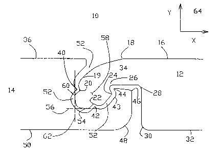
Referring now to the drawings, FIG. 1A is a schematic close-up side view
illustrating the
flexible interlocking joint of the interlocking elements in a neutral, i.e.,
non-flexed, non-contact,
position. The flexible interlocking joint, in a neutral position, generally
referenced as 10, is
formed from interlocking, mechanically engaging or mating two interlocking
elements, which are
partially shown here and generally referenced as interlocking element end 12
and interlocking
element end 14. Element end 12 features a contour including element top
surface segment 16
extending horizontally to bend 18, further extending downward along an incline
to bend 20,
further extending downward and around to bend 22, further extending upward and
around to
bend 24, further extending upward along an incline to bend 26, further
extending horizontally to
bend 28, further extending vertically downward to bend 30, and further
extending horizontally
along element bottom surface segment 32. That part of the contour of element
end 12, extending
from bend 18 through bends 20 and 22, and through bends 24, 26, and 28, forms
a male type
element or joint interlocking component, tongue 34.
Element end 14 features a contour including element top surface segment 36
extending
horizontally to bend 38, further extending downward along an incline to bend
40, further
extending downward and around to bend 42, further extending upward and around
bend 43,
further extending upward and around to bend 44, further extending downward
along an incline to
bend 46, further extending vertically downward to bend 48, and further
extending horizontally
16
CA 02372979 2001-11-02
WO 00/68506 PCT/IL00/00254
along element bottom surface segment 50. The contour of element end 14,
extending from bend
38 through bends 40 and 42, and through bend 46, forms a female type element
or joint
interlocking component, channel 52.
Channel 52 of element end 14, is contoured, of variable shape having variable
dimensions, appropriate for insertion or mechanical engagement of tongue 34 of
element end 12,
providing a joint for flexibly locking elements of a ground surface cover
system for erosion
control. Further illustration and description of preferred shapes and
dimensions of tongue 34 and
of channel 52 are provided in FIGS. 4D - 4E. The presence of tongue 34 of
element end 12,
inside of channel 52 of element end 14, forms flexible interlocking joint 10.
Flexible
interlocking joint 10 has dual functionality, enabling mufti-directional and
angular flexibility or
movement of tongue 34 relative to channel 52, following engagement of tongue
34 with channel
52, simultaneous to enabling the corresponding elements to remain in an
interlocked position.
By design, disengagement of tongue 34 from channel 52 is limited to a small
range of positions
and angles of tongue 34 relative to channel 52, according to actual relative
shapes and
dimensions of tongue 34 and channel 52, in general, and, in particular, due to
the presence of
tongue surface segment extending along bend 22, bend 24, and bend 26 relative
to the presence
of channel surface segment extending along bend 43, bend 44, and bend 46. This
dual
functionality is directly translated to the ground surface cover system of the
present invention for
the objective of providing a feasible and effective system of erosion control.
Tongue 34 of element end 12 includes tongue tip 58, where tongue tip 58
features the
region extending from bend 20 through bend 22. Tongue tip 58 includes a tongue
tip bottom 54,
with a corresponding tongue tip bottom tangent 56 drawn as reference, and a
tongue tip side 60,
with a corresponding tongue tip side tangent 62 drawn as reference. Coordinate
system 64,
featuring an x-axis positioned 90 degrees from, or perpendicular to, a y-axis,
is included in FIG.
17
CA 02372979 2001-11-02
WO 00/68506 PCT/IL00/00254
1A as reference for the purpose of describing the positioning and flexibility
of the flexible joint
of the interlocking elements of the present invention. For the flexible joint
10 illustrated in
FIG. 1A in the neutral position, tongue tip bottom tangent 56 is parallel to
the x-axis, and tongue
tip side tangent 62 is parallel to y-axis, of coordinate system 64,
respectively. Moreover, for
5 flexible joint 10 in the neutral position, tongue 34 is mechanically
engaged, but not in physical
contact with, element end 14, whereby a gap exists between the contour of
tongue 34 and the
contour of channel 52. For the preferred embodiment of the invention, bottom
surface segment
32 of element end 12 lies parallel to and in the same plane as bottom surface
segment 50 of
element end 14.
10 FIG. 1B is a schematic close-up side view illustrating the flexible
interlocking joint of the
interlocking elements following angular movement. The flexible interlocking
joint, following
angular movement, generally referenced as 66, is formed by rotation of element
end 12 with
respect to element end 14. In this illustration, element end 12 is rotated
counterclockwise
through an angle 68, with coordinate system 64 as reference point of rotation.
In practice,
according to actual dimensions of tongue 34 and channel 52, angle 68 is
preferably less than
sixty degrees. For flexible joint 66 illustrated in FIG. 1B in the flexed
angular position, tongue
tip bottom tangent 56 is rotated away from the x-axis, and tongue tip side
tangent 62 is rotated
away from the y-axis, of coordinate system 64, respectively, through angle 68.
Moreover, for
flexible joint 66 in the flexed angular position, tongue 34 may be in physical
contact with
element end 14, and preferably, bottom surface segment 32 of element end 12 is
positioned at an
angle with respect to bottom surface segment 50 of element end 14.
FIG. 1C is a schematic close-up side view illustrating the flexible
interlocking joint of the
interlocking elements following horizontal movement. The flexible interlocking
joint, following
horizontal movement, generally referenced as 70, is formed by horizontal or
lateral movement of
18
CA 02372979 2001-11-02
WO 00/68506 PCT/IL00/00254
element end 12 with respect to element end 14. In this illustration, element
end 12 is
horizontally moved a distance 72, along tongue tip bottom tangent 56, where
distance 72 is
represented by the distance between new tongue tip side tangent 74 and neutral
position tongue
tip side tangent 62 (of FIG. 1 A), with coordinate system 64 as reference
point of horizontal
movement. For the horizontal movement of flexible joint 70, tongue tip bottom
tangent 56 is
parallel to the x-axis, and new tongue tip side tangent 74 is parallel to y-
axis, of coordinate
system 64, respectively. Moreover, for flexible joint 70 in this flexed
position following
horizontal movement, according to extent of horizontal movement, tongue 34 may
be in physical
contact with element end 14. This is indicated by contact point 76, where bend
24 of tongue 34
is in contact with the surface region of channel 52 of element end 14.
Preferably, following
horizontal movement of element end 12 with respect to element end 14, bottom
surface segment
32 of element end 12 lies paxallel to and in the same plane as bottom surface
50 segment of
element end 14.
FIG. 1D is a schematic close-up side view illustrating the flexible
interlocking joint of the
interlocking elements following vertical movement. The flexible interlocking
joint, following
vertical movement, generally referenced as 78, is formed by vertical movement
of element end
12 with respect to element end 14. In this illustration, element end 12 is
vertically moved up a
distance 80, along tongue tip side tangent 62, where distance 80 is
represented by the distance
between new tongue tip bottom tangent 82 and neutral position tongue tip
bottom tangent 56 (of
FIG. 1 A), with coordinate system 64 as reference point of vertical movement.
For vertical
movement of flexible joint 78, new tongue tip bottom tangent 82 is parallel to
the x-axis, and
tongue tip side tangent 62 is parallel to y-axis, of coordinate system 64,
respectively. Moreover,
for flexible interlocking joint 78 in this flexed position following vertical
movement, according
to extent of vertical movement, tongue 34 may be in physical contact with
element end 14. This
19
CA 02372979 2001-11-02
WO 00/68506 PCT/IL00/00254
is indicated by contact point 84 and contact point 86, where surface region of
channel 52 of
element end 14 extending from bend 40 to bend 38 is in contact with the
surface of tongue 34 of
element end 12. Preferably, following vertical movement of element end 12 with
respect to
element end 14, bottom surface segment 32 of element end 12 lies parallel to
and in a different
plane as bottom surface segment 50 of element end 14.
It is to be noted that flexible interlocking joints 10, 66, 70, and 78,
featured components,
and different positions of movement or flexibility thereof, as illustrated in
FIGS. 1A - 1D, are
representative of the interlocking elements forming the ground surface cover
system of the
present invention. Interlocking element top surface regions in continuity
with, and extending
from top surface segment 16, or extending from top surface segment 36, to the
opposite element
end (not shown in FIGS. 1A - 1D) of the same corresponding interlocking
element may be of
variable configuration, including, but not limited to, level, ridged, or
elevated, with variable
dimensions. Likewise, interlocking element bottom surface regions in
continuity with, and
extending from bottom surface segment 32, or extending from bottom surface
segment 50, to the
opposite element end (not shown in FIGS. 1A - 1D) of the same corresponding
interlocking
element may be of variable configuration, including, but not limited to,
level, ridged, or elevated,
with variable dimensions.
FIG. 2A is a schematic side view illustrating part of the system featuring
level top and
bottom configured elements interlocked by the flexible interlocking joint. The
part of the system
featuring level top and bottom co~gured elements interlocked by flexible
joints 90 and 92, is
generally referenced as 88. In this figure, interlocking element top surface
segment 94, in
continuity with, and extending from element end top surface segment 16 to
element opposite end
top surface segment 36 is configured as level. Interlocking element bottom
surface segment 96,
in continuity with, and extending from element end bottom surface segment 32
to element
CA 02372979 2001-11-02
WO 00/68506 PCT/IL00/00254
opposite end bottom surface segment 50 is also configured as level. In system
88, flexible joints
90 and 92, featuring element or joint tongue 34 mechanically engaged to
element or joint channel
52 are variably positioned and flexible according to the description provided
in FIGS. 1A - 1D.
FIG. 2B is a schematic side view illustrating part of the system featuring
ridged top and
bottom configured elements interlocked by the flexible interlocking joint. The
part of the system
featuring optional ridged top and bottom configured elements interlocked by
flexible joints 100
and 102, is generally referenced as 98. In this figure, interlocking element
top surface segment
104, in continuity with, and extending from element end top surface segment 16
to element
opposite end top surface segment 36 is configured as ridged. Exemplary ridge
106 of ridged
configured interlocking element top surface segment 104 may be of variable
dimensions and
frequency, as described in detail in FIG. 5A. Interlocking element bottom
surface segment 108,
in continuity with, and extending from element end bottom surface segment 32
to element
opposite end bottom surface segment 50 is also configured as ridged. Exemplary
ridge 110 of
ridged configured interlocking element bottom surface segment 108 may also be
of variable
dimensions, as described in detail in FIG. 5A. In system 98, flexible joints
100 and 102,
featuring element or joint tongue 34 mechanically engaged to element or joint
channel 52, axe
variably positioned and flexible according to the description provided in
FIGS. 1A - 1D.
The presence of ridges along the top surface and/or bottom surface of one or
more of the
interlocking elements is functional with respect to hydrological, stability,
and landscape
properties of the ground surface cover system for erosion control. Ridged
configured
interlocking element top surface segment 104 enables control of, and affects
water flow and
water distribution throughout the system of interlocking elements, based on
interaction of
flowing water with the ridges. Ridged configured interlocking element bottom
surface segment
108 enables control of, and improves anchoring of the system of interlocking
elements, based on
21
CA 02372979 2001-11-02
WO 00/68506 PCT/IL00/00254
interaction of the ground surface with the ridges 110. This alternative
feature of the interlocking
elements of the invention results in a more stable erosion control system with
respect to water
flow and water distribution during possible ground movement due to an erosion
process.
Another result of increased stability is better preservation of botanic
landscape which may be
placed in spaces in between interlocking elements.
FIG. 2C is a schematic side view illustrating part of the system featuring an
elevated level
top and level bottom configured element interlocked by the flexible
interlocking joint. The part
of the system featuring an optional elevated level top configured element 118
interlocked to a
level top and level bottom configured element 120 by flexible joint 114, which
in turn is
interlocked to another level top and level bottom configured interlocking
element 122 by flexible
joint 116, is generally referenced as 112. In this figure, element top surface
region 124 of
element 118 in continuity with, and extending from element end top surface
segment 16 to
element opposite end top surface segment 36, is configured as elevated, and
features level top
surface segment 125. Element bottom surface segment 126 of element 118 is
shown as level
configured, but may be configured as, including, but not limited to, level,
ridged, or elevated.
Exemplary elevated configured interlocking element top surface region 124 may
be of variable
dimensions, as described in detail in FIG. 6A. In system 112, flexible joints
114 and 116,
featuring element or joint tongue 34 mechanically engaged to element or joint
channel 52, are
variably positioned and functional according to the description provided in
FIGS. 1A - 1D.
The presence of an elevated element top surface region of one or more of the
interlocking
elements is functional with respect to hydrological properties of the ground
surface cover system
for erosion control. Elevated configured interlocking element top surface
region 124 enables
control of, and affects water flow and water distribution throughout the
system of interlocking
elements, based on interaction of flowing water with the elevation.
22
CA 02372979 2001-11-02
WO 00/68506 PCT/IL00/00254
FIG. 3 is a schematic side view illustrating part of the system featuring
level top and level
bottom configured elements interlocked to a level top and level bottom
configured center
element, via the flexible interlocking joint. As shown in FIG. 3, center
interlocking element 130
features two identical element or joint channels 52 (FIG. 1A), each being
compatible for
mechanical engagement via mating or interlocking to an element or joint tongue
34 (FIG. 1A) of
another interlocking element. The part of the system featuring a level top
configured center
element 130 interlocked to a first, level top and level bottom configured
element 132 by flexible
joint 136, and interlocked to a second, level top and level bottom configured
interlocking element
134 by flexible- joint 138, is generally referenced as 128. In this figure,
center element top
surface segment 140, and center element bottom surface segment 142, of center
element 130, are
each configured as level, but each center element surface segment 140 or 142
may be configured
as, including, but not limited to, level, ridged, or elevated, in accordance
with the descriptions of
FIGS. 2A - 2C. Exemplary level configured interlocking element 130 may be of
variable
dimensions, as described in detail in FIG. 7. In system 128, flexible joints
136 and 138, featuring
element or joint tongue 34 mechanically engaged to element or joint channel
52, are variably
positioned and functional according to the description provided in FIGS. 1A -
1D.
In addition to being another interlocking element of the ground surface cover
system,
center interlocking element 130 is uniquely functional with respect to
enabling convenient and
efficient installation of a series of interlocking elements along the bottom,
and along both sides,
of ground featuring a double incline, as illustrated and described in FIG. 11.
FIG. 4A is a schematic view illustrating one side of a level top and level
bottom
configured interlocking element. Exemplary interlocking element 144 may be of
variable overall
element length 148 and of variable overall element height 146. The contour of
side 150 of
interlocking element 144 includes element end level top surface segment 16,
extends outward
23
CA 02372979 2001-11-02
WO 00/68506 PCT/IL00/00254
and down past bend 18, features element or joint tongue 34, in continuity
with, and extending
down and around to element level bottom surface segment 32, an element
opposite end level top
surface segment 36, extends outward and down past bend 38, features element or
joint channel
52, in continuity with, and extending down and around to element level bottom
surface segment
50, an element middle level top surface segment 94, in continuity with, and
extending between
element end level top surface segments 16 and 36, and an element middle level
bottom surface
segment 96, in continuity with, and extending between element end level bottom
surface
segments 32 and 50. Side 150 of element 144 features element level top surface
segments 36,
94, and 16, all positioned in a same plane, and element level bottom surface
segments 50, 96, and
32, all positioned in a different same plane, whereby the plane of element top
surface segments is
parallel to the plane of element bottom surface segments, with coordinate
system 64 as reference.
FIG. 4B is a schematic view illustrating the top of level top and bottom
configured
interlocking element 144 of FIG. 4A. Top 152 of interlocking element 144
includes element
level top surface regions 36, 94, and 16, and top profiles of surface regions
of element or joint
tongue 34 and element or joint channel 52, corresponding to side 150 of FIG.
4A. Top 152 of
exemplary interlocking element 144 features element width 154, element half
length 147, each of
variable dimensions, and element side 156 opposite to element side 150 shown
in FIG. 4A.
In a preferred alternative embodiment of the level top and level bottom
interlocking
element of the present invention, an element side, for example, element side
150 as shown in
FIG. 4B, features optional pin groove 158, preferably located along the center
of element side
150 at element half length 147, of variable geometry and dimensions,
preferably configured as an
open trapezoid, spanning element volume vertically along entire element height
146 of element
side 150 of level top and level bottom interlocking element 144. Pin groove
158 provides space
for optional insertion of a pin (not shown), starting from the top opening of
pin groove 158 and
24
CA 02372979 2001-11-02
WO 00/68506 PCT/IL00/00254
positioned vertically downward along the side of one interlocking element, or
starting from the
top opening of pin groove 158 and positioned vertically downward between the
sides of two
adjacent interlocking elements, respectively, of the ground surface cover
system. The optional
use of pins along the interlocking elements is primarily for increased holding
strength and
stability of those elements positioned at the top, bottom, or critical
locations, of inclined ground,
where such elements maintain a larger load of other interlocking elements of
the system, as is
further illustrated and described in FIGS. 9 - 11.
In another preferred alternative embodiment of the interlocking elements of
the present
invention, an element side, for example, element side 150, as shown in FIG.
4B, features optional
I O water channel 160, preferably located along the center of element side 150
at element half length
147, of variable geometry and dimensions, preferably configured as an open
half donut, spanning
element volume along part of element height 146 along element side 150 of
level top and level
bottom interlocking element 144. Water channel 160 functions to channel or
trap water, enabling
additional control of water flow and distribution throughout the erosion
control system of
interlocking elements during conditions of rainfall.
FIG. 4C is a schematic side view illustrating alternative optional features of
the level top
and bottom configured interlocking element 144 of FIGS. 4A - 4B. Optional pin
groove 158, and
optional water channel 160 are shown configured as part of element side 150.
Optional pin
groove 158 spans element volume vertically along entire element height 146,
and optional water
channel 160 spans element volume along part of element height 146 of level top
and level bottom
interlocking element 144. Element level bottom surface segment 162 of element
side 150
corresponds to element level bottom surface segments 50, 96, and 32, of
element 144 (FIG. 4A).
FIG. 41D is a perspective view of level top and bottom configured interlocking
element
144 of FIGS. 4A - 4C, featuring element or joint tongue 34 pointing downward,
and element or
CA 02372979 2001-11-02
WO 00/68506 PCT/IL00/00254
joint channel 52 pointing upward. The upper outer surface contour of joint
tongue 34, extending
outward and sloping downward from element surface bend 18 (FIG. 1) to joint
tongue side tip 60
(FIG. 1), is of variable geometry, preferably, but not limited to, polygonal
stepped, but may also
be curved and smooth. Of polygonal stepped geometry, joint tongue surface
steps 166, separated
and bordered by joint tongue surface step edges 168, are preferably level and
rectangular in shape
having variable step width 170 and variable step number, e.g., shown here are
three joint tongue
surface steps 166, extending parallel to and along entire element width 154,
from element surface
bend 18 to element surface bend 164, of element 144. Optional pin groove 158,
and optional
water channel 160 are shown as part of side 150 of element 144.
FIG. 4E is a perspective view of level top and bottom configured interlocking
element
144 of FIGS. 4A - 4C, featuring element or joint tongue 34 pointing upward,
and element or
joint channel 52 pointing downward. FIG. 4E shows element 144 of FIG. 4D
turned over. The
upper outer surface contour of joint channel 52, extending outward and sloping
downward from
element surface bend 48 (FIG. 1 ) to joint channel bend 46 (FIG. 1 ), is of
variable geometry,
preferably, but not limited to, polygonal stepped, but may also be curved and
smooth. Of
polygonal stepped geometry, joint channel surface steps 172, separated and
bordered by joint
channel surface step edges 174, are preferably level and rectangular in shape
having variable step
width 176 and variable step number, e.g., shown here are three joint channel
surface steps 172,
extending parallel to and along entire element width 154, from element surface
bend 48 to
element surface bend 178, of element 144. Perspective side views of optional
pin groove 158,
and optional water channel 160 are shown as part of side 150 of element 144.
The functionality of the downward sloping surface contours of element or joint
tongue 34
and element or joint channel 52 is for enabling water drainage down and along
the outer surfaces
of the interlocking elements. For a ground surface cover system featuring a
pattern of several
26
CA 02372979 2001-11-02
WO 00/68506 PCT/IL00/00254
interlocking elements of the present invention, the downward sloping contours
of a multitude of
interlocked flexible joint tongues 34 and joint channels 52 forms extended
lanes for which water
can freely flow, in a guided manner according to the particular system
geometric pattern and
ground topography.
The perspective views of element 144 described and shown in FIGS. 4D and 4E
are
exemplary, whereby features, components, configurations, geometries, and
relative positioning
thereof, relating to element or joint tongue 34, element or joint channel 52,
sides 150 and 156,
optional pin groove 158, and optional water channel 160, are applicable to the
other interlocking
elements of the present invention.
FIG. 5A is a schematic view illustrating one side of a ridged top and bottom
configured
interlocking element. Exemplary ridged top and ridged bottom interlocking
element 180 may be
of variable overall element length 198, element half length 197, and of
variable overall element
height 200. The contour of element side 194 of ridged interlocking element 180
includes
element end level top surface segment 16, extends outward and down past bend
18, features
element or joint tongue 34, in continuity with, and extending down and around
to element level
bottom surface segment 32, an element opposite end level top surface segment
36, extends
outward and down past bend 38, features element or joint channel 52, in
continuity with, and
extending down and around to element level bottom surface segment 50, an
element middle
ridged top surface segment 104, in continuity with, and extending between
element end level top
surface segments 16 and 36, and an element middle ridged bottom surface
segment 108, in
continuity with, and extending between element end level bottom surface
segments 32 and 50.
Side 194 of ridged element 180 features element top surface segments 36, 104,
and 16, all
positioned in a same plane, and element bottom surface segments 50, 108, and
32, all positioned
27
CA 02372979 2001-11-02
WO 00/68506 PCT/IL00/00254
in a different same plane, whereby the plane of element top surface segments
is parallel to the
plane of element bottom surface segments, with coordinate system 64 as
reference.
In FIG. 5A, element middle ridged top surface segment 104 is of variable
length
extending between element level top surface segment 36 to element level top
surface segment 16.
Ridged top surface segment 104 features ridges 106 of variable dimensions,
including ridge
upper segment length 182, ridge lower segment length 184, ridge height 186,
and ridge segment
angles 188, 190, and 192. Oppositely positioned element middle ridged bottom
surface segment
108 is of variable length extending between element level bottom surface
segment 32 to element
level bottom surface segment 50. Ridged bottom surface segment 108 features
ridges 110 of
variable dimensions (not referenced), similar to the dimensions of ridged top
surface segment
104, including ridge upper segment length, ridge lower segment length, ridge
height, and ridge
segment angles. Preferably, element top surface ridges 106, and element bottom
surface ridges
110, are parallel to each other, along the x-axis of reference coordinate
system 64, throughout
length 198 of ridged element 180.
In a preferred alternative embodiment of the present invention, ridged top and
ridged
bottom interlocking element 180 features optional pin groove 196 (shown in
FIG. 5A as dashed
lines, representing position of the pin groove in the plane of the page, as
part of element side 193
located opposite to element side 194, shown in FIG. 5B), preferably located
along the center of
element side 193 at element half length 197, of variable geometry and
dimensions, and
preferably configured as an open trapezoid, spanning vertically along element
height 200 of
ridged interlocking element 180. Similar to the preferred alternative
embodiment of level top
and level bottom interlocking element 144 of FIG. 4B, pin groove 196 provides
space for
optional insertion of a pin (not shown), starting from the top opening of pin
groove 196 and
positioned vertically downward along the side of one interlocking element, or
starting from the
28
CA 02372979 2001-11-02
WO 00/68506 PCT/IL00/00254
top openings and positioned vertically downward between the sides of two
adjacent interlocking
elements, respectively, of the ground surface cover system.
FIG. 5B is a schematic view illustrating the top of the ridged top and bottom
configured
interlocking element 180 of FIG. 5A. Top surface of exemplary ridged
interlocking element 180
includes element ridged top surface region 104 featuring ridges 106, element
level top surface
regions 36 and 16, and top profiles of surface regions of element or joint
tongue 34 and element
or joint channel 52, corresponding to side 194 of FIG. 5A. Preferably, element
top surface ridges
106 are parallel to each other, along the x-axis of reference coordinate
system 64, throughout
length 198 of ridged element 180. Top surface of ridged interlocking element
180 features
element width 204 of variable dimension, and element opposite side 193
featuring pin groove
196, located opposite to element side 194.
FIG. 6A is a schematic view illustrating one side of an elevated level top and
level
bottom configured interlocking element. In this alternative preferred
embodiment, exemplary
interlocking element 208 may be of variable overall element length 210,
element half length 209,
and of variable overall element height 212. The contour of side 214 of
interlocking element 208
includes element end level top surface segment 16, extends outward and down
past bend 18,
features element or joint tongue 34, in continuity with, and extending down
and around to
element level bottom surface segment 32, an element middle level bottom
surface segment 96, in
continuity with, and extending between element end level bottom surface
segments 32 and 50,
extends up and around element or joint channel 52, in continuity with, and
extending up and
around bend 38 to element opposite end level top surface segment 36, extends
around bend 216,
up and around bend 218, along element elevated level top surface segment 125,
around bend 220,
down and around bend 222, and extends back to element level top surface
segment 16.
29
CA 02372979 2001-11-02
WO 00/68506 PCT/IL00/00254
In FIG. 6A, element elevated level top surface segment 125 extends between
element end
level top surface segments 16 and 36. Element elevated level top surface
region 124 is of
variable geometry with variable dimensions. Element elevated level top surface
region 124 is
preferably, but not limited to, a rectangle of elevated top length 224 and
elevated top height 226.
Element side 214 of element 208 includes element level bottom surface segments
32, 96, and 50,
positioned in a first same plane, element level top surface segments 16 and
36, positioned in a
second same plane, and element elevated level top surface segment 125
positioned in a third
plane, whereby all three planes of surface segments are parallel to each
other, with coordinate
system 64 as reference.
In a preferred alternative embodiment of the elevated level top and level
bottom
interlocking element of the present invention, element 208 features optional
pin groove 226
(shown in FIG. 6A as dashed lines, representing position of the pin groove in
the plane of the
page, as part of element side 213 located opposite to element side 214),
preferably located along
the center of element side 214 at element half length 209, of variable
geometry and dimensions,
and preferably configured as an open trapezoid, spanning vertically along
element height 212 of
elevated level top interlocking element 208, and having the same function of
providing space for
optional insertion of a pin (not shown), starting from the top opening of pin
groove 226 and
positioned vertically downward along the side of one interlocking element, or
starting from the
top opening of pin groove 226 and positioned vertically downward between the
sides of two
adjacent interlocking elements, respectively, of the ground surface cover
system, as described for
level top and level bottom interlocking element 144 of FIG. 4B, and for ridged
top and ridged
bottom interlocking element 180 of FIG. 5A.
FIG. 6B is a schematic view illustrating the top of elevated level top and
level bottom
configured interlocking element 208 of FIG. 6A. Top surface of exemplary
elevated level top
CA 02372979 2001-11-02
WO 00/68506 PCT/IL00/00254
and level bottom interlocking element 208 includes elevated level top surface
region 125, top
profiles of surface segments extending from bend 216 to bend 218, and
extending from bend 220
to bend 222, element level top surface regions 36 and 16, and top profiles of
surface regions of
element or joint tongue 34 and element or joint channel 52, corresponding to
side 214 of FIG.
6A. Top surface of elevated level top interlocking element 208 features
element width 228 of
variable dimension, and element opposite side 213 featuring optional pin
groove 226, located
opposite to element side 214 as shown in FIG. 6A. Preferably, element top
surface segments
216, 218, 220, and 222, and element top surface segments formed by extension
of each bend 38
and bend 18 across width 228 of element 208, are parallel to each other, along
the x-axis of
reference coordinate system 64, throughout element length 210 of elevated
level top element 208.
FIG. 7 is a schematic view illustrating one side of a level top and bottom
configured
center interlocking element. Exemplary center interlocking element 130
features two identical
element or joint channels 52, each being compatible for mechanical engagement
via mating or
interlocking to an element or joint tongue 34 of another interlocking element.
Center element
130 may be of variable overall element length 232 and of variable overall
element height 234.
The contour of element side 236 of center element 130 includes two element end
level top
surface segments 36, each extending outward and down past bend 38, features
two element or
joint channels 52, each in continuity with, and extending down and around to
element level
bottom surface segment 50, an element middle level top surface segment 94, in
continuity with,
and extending between element end level top surface segments 36, and an
element middle level
bottom surface segment 96, in continuity with, and extending between element
end level bottom
surface segments 50. Element side 236 of element 130 features element level
top surface
segments 36 and 94 positioned in a same plane, and element level bottom
surface segments 50
and 96 positioned in a different same plane, whereby the plane of element top
surface segments
31
CA 02372979 2001-11-02
WO 00/68506 PCT/IL00/00254
is parallel to the plane of element bottom surface segments, with coordinate
system 64 as
reference.
In a preferred alternative embodiment of the present invention, level top and
level bottom
center interlocking element 130 features optional pin groove 238 (shown in
FIG. 7 as dashed
lines, representing position of the pin groove in the plane of the page, as
part of element side
located opposite to element side 236), preferably located along the center of
element side 236 at
element half length 231, of variable geometry and dimensions, and preferably
configured as an
open trapezoid, spanning vertically along element height 234 of level top and
level bottom center
interlocking element 130, and having the same function of providing space for
optional insertion
of a pin (not shown), as previously described and shown in FIGS. 4B - 6B.
FIG. 8 is a schematic sequential series of side views illustrating a method of
interlocking
the elements via the flexible interlocking joint. In the sequential series of
side views 240A
through 240E illustrating a preferred method of interlocking the elements via
the flexible joint of
the present invention, exemplary level top and level bottom interlocking
element 242 featuring
tongue 34 is to be mechanically engaged or interlocked to exemplary level top
and level bottom
interlocking element 244 featuring channel 52. Channel 52 of element 244 is
appropriately
contoured for insertion or mechanical engagement of tongue 34 of element 242.
Insertion or
engagement of tongue 34 into channel 52 is limited to a small range of
positions and angles of
tongue 34 relative to channel 52, according to actual relative shapes and
dimensions of tongue 34
and channel 52. In particular, the objective is to insert tongue 34, having a
configuration
featuring tongue surface region contour extending along bends 26, 24, 22, and
19, with a widest
chord 246 extending between bend 24 and bend 19, into channel 52, having a
configuration
featuring channel surface region contour extending along bends 46, 44, 43, and
38, with an
opening chord 248 extending between bend 44 and bend 38.
32
CA 02372979 2001-11-02
WO 00/68506 PCT/IL00/00254
The method of insertion of tongue 34 of element 242 into channel 52 of element
52 is
straightforward and is based on positioning element 242 through a sweeping
range of decreasing
angles 250 such to enable mechanical engagement of the elements, where angle
250 is the angle
formed between tongue tip bottom tangent 56 (FIG. 1) and line 57, where line
57 is parallel to
the x-axis of reference coordinate system 64. The process of inserting tongue
34 of element 242
into channel 52 of element 244 until mechanical engagement is attained, is
continued until angle
250 is approximately zero, where in such position, tongue tip bottom tangent
56 is parallel to and
in the same plane as line 57. The process of mechanical engagement or
interlocking opposing
ends of a pair of opposing interlocking elements is completely reversible
i.e., mechanical
disengagement or unlocking opposing ends of a pair of interlocked interlocking
elements is
readily accomplished by reversing the above process, with reference to the
reverse of the
sequence illustrated FIG. 8. This reversible process is sequentially
illustrated in the series of side
views 240A through 240D.
Side view 240E illustrates an extreme horizontal position of element 242
interlocked to
element 244 via the flexible joint. Following completion of initial engagement
of the elements,
side view 240D, elements 242 and 244 are flexed or moved horizontally with
respect to each
other along the plane of the x-axis of reference coordinate system 64, such
that surface segment
of tongue 34, extending between bends 24 and 26, is in substantial physical
contact with surface
segment of channel 52, extending between bends 43 and 44, as described and
illustrated in FIG.
1C. This method of mechanical engagement or interlocking of elements is
applicable to all
elements featured in this invention.
FIGS. 9A through 9C are schematic top views of different preferred embodiments
of
patterns of the system of interlocking elements featuring flexible
interlocking joints, and
corresponding methods of forming the different patterns. Patterns 262 through
266 could feature
33
CA 02372979 2001-11-02
WO 00/68506 PCT/IL00/00254
any combination of the various configurations of level, ridged, elevated, or
center, interlocking
elements already described and illustrated in this invention, however, for
illustrative purposes,
exemplary level top and level bottom interlocking elements 144 described and
illustrated in
particular, in FIGS. 2A, and 4A - 4E, are referred to here. Optional pin
groove 158 of
interlocking element 144 is shown throughout the different patterns of the
system in FIGS. 9A -
9C for illustrative purpose only, and its presence is not meant to be limiting
with respect to the
present invention. The detailed method of mechanically engaging or
interlocking individual
elements is applicable here, and includes the description and illustrations
related to FIG. 8.
Moreover, the method of mechanically engaging or interlocking individual
elements is
completely reversible, whereby, patterns of the system of interlocked elements
can be partly, or
completely, taken apart by mechanically disengaging or unlocking the
interlocked elements via
the flexible interlocking joint.
FIG. 9A is a schematic top view of the system of interlocking elements, and
the method
of forming a closed, non-staggered pattern. Exemplary closed pattern 262 of
interlocking
elements features rows 252A through 252D of interlocking elements, and columns
254A through
254D of interlocking elements.
According to relative directions and geometries of the features and components
of
interlocking elements 144 shown in the side, top, and perspective views of
FIGS. 2A, and 4A -
4E, using coordinate system 64 as reference, right end row 252A features
element tongues 34
exposed and non-interlocked and element channels 52 interlocked to element
tongues 34 of
adjacent row 252B, middle rows 252B and 252C feature element tongues 34 and
element
channels 52 interlocked and mechanically engaged to corresponding element
channels 52 and
element tongues 34, of corresponding adjacent rows, and end row 252D features
element tongues
34 interlocked to element channels 52 of adjacent row 252C and element
channels 52
34
CA 02372979 2001-11-02
WO 00/68506 PCT/IL00/00254
unoccupied and non-interlocked. In pattern 262, rows 252A through 252D are
adjacent to each
other in that row interfaces 256 feature tongues 34 interlocked to channels
52, thereby, forming
rows of the flexible interlocking joint of the present invention.
A preferred method of forming the system featuring closed, non-staggered
pattern 262 is
by initially forming row 252A, featuring tongues 34 facing outside, and
exposed and
non-interlocked, by placing element sides 150 and 156 of interlocking elements
144 immediately
adjacent to each other, leaving no space between them. Following completion of
closed pattern
row 252A, additional rows 252B through 252D are formed by interlocking or
mechanically
engaging entire width 154 (FIG. 4D) of tongue 34 of each added interlocking
element 144 to an
entire width 154 of channel 52 of one other interlocking element 144 of a
previous row, until a
new row is complete, thereby forming columns 254A through 254D, such that all
element side to
element side interfaces 258 of a given column of interlocking elements 144 are
positioned
parallel to each other and in the same vertical plane, with respect to
reference coordinate system
64.
FIG. 9B is a schematic top view of the system of interlocking elements, and
the method
of forming a closed, staggered pattern. Pattern 264 shown in FIG. 9B is
closed, as described and
shown for pattern 262 in FIG. 9A, whereby rows 252A through 252D feature
element sides 150
and 156 of exemplary interlocking elements 144 immediately adjacent to each
other, without
space between them, thereby forming element to element interfaces 258
extending across each
row.
A preferred method of forming the system featuring closed, staggered pattern
264 is by
initially forming row 252A, featuring tongues 34 facing out, exposed and non-
interlocked, by
placing element sides 150 and 156 of interlocking elements 144 immediately
adjacent to each
other, leaving no space between them. Following completion of closed pattern
row 252A,
CA 02372979 2001-11-02
WO 00/68506 PCT/IL00/00254
additional rows 252B through 252D are sequentially formed by interlocking or
mechanically
engaging each tongue 34 of interlocking elements 144 to two separate channels
52 of two
adjacent interlocking elements 144. According to this method, separate and
distinguishable sets
of columns, i.e., columns 254A through 254D, and columns 255A through 255C,
are formed
such that element side to element side or column interfaces 258 of each of the
two formed sets of
columns of interlocking elements 144 are horizontally located in alternate
rows 252A through
252D, positioned parallel to each other, and in the same plane, with respect
to reference
coordinate system 64.
Staggered pattern 264 illustrated in FIG. 9B is periodic, whereby staggered
positions of
interlocking elements 144 are periodic in alternating rows, e.g., positions of
element sides 150
and 156, and interfaces 258 in row 252A are in the same x-axis planes as
positions of element
sides and interfaces in row 252C, and likewise for alternating rows 252B and
252D. This
represents a special case of staggered patterns of the system of interlocking
elements of the
present invention, where, in general, the staggered patterns of interlocking
elements need not be
periodic.
FIG. 9C is a schematic top view of the system of interlocking elements, and
the method
of forming an open, staggered pattern. Pattern 266 shown in FIG. 9C is open,
whereby rows
252A through 252D feature a number of interlocking elements and corresponding
element sides
150 and 156 of exemplary interlocking elements 144 spaced apart, forming
variable sized
rectangular regions 268 surrounded by a variable number of elements, according
to specific
location of a given region 268. As a result of featuring openings in the
system of interlocking
elements, pattern 266 is staggered, in accordance with the description of FIG.
9B.
A preferred method of forming the system featuring open, staggered pattern 266
is by
placing element sides 150 and 156 of interlocking elements 144 at variable
distances from each
36
CA 02372979 2001-11-02
WO 00/68506 PCT/IL00/00254
other, leaving variable spaces between selected elements 144, and interlocking
or mechanically
engaging each tongue 34 of interlocking elements 144 to two separate, not
necessarily equal parts
of channels 52 of two interlocking elements 144, thereby forming non-periodic
rows 252A
through 252D, of elements, where elements 144 are positioned in variable x-
axis planes with
S respect to reference coordinate system 64.
Features and capabilities of flexibility and directional movement of the
flexible
interlocking joint of the present invention (FIGS. 1A - 1D) are all applicable
to the interlocking
elements and joints formed thereof in the different preferred embodiments of
patterns of the
ground surface cover system of erosion control described and illustrated in
FIGS. 9A - 9C.
Applying the property of flexibility of the interlocking joints to the
installation and use of the
interlocking elements featured in the different system patterns provides
significant capability of
custom designing an effective ground surface cover system for erosion control
for a wide variety
of erosion prone ground surface topographies. This translates to achieving the
main objective of
effectively controlling or minimizing ground movement during a potential
erosion process, by
designing an erosion control system which provides high strength and long term
stability,
patterns for efficient water flow and water distribution, flexible adjustment
to ground movement,
capability of including landscape, economic and feasible manufacturing and
installation,
replaceability, and reusability.
Flexibility of individual pairs of interlocked elements is directly scalable
to flexibility of
an overall ground surface cover erosion control system. For example, system
pattern 262 of FIG.
9A should be well suited to erosion prone ground surface requiring a firm,
closed, non-staggered,
but flexible surface cover, whereas, system pattern 266 of FIG. 9C should be
well suited to
erosion prone ground surface featuring botanic landscape, where, in addition
to providing space
for inclusion of botanic landscape in between the interlocking elements of the
ground surface
37
CA 02372979 2001-11-02
WO 00/68506 PCT/IL00/00254
cover system, it is desirable that at least part of the water flow be directed
into the ground in the
regions of botanic growth.
FIG. 10 is a side view diagram of the ground surface cover system of
interlocking
elements, as applied in practice to an exemplary single inclined ground
surface featuring a cavity
and a protrusion, illustrating flexibility of the system. Ground surface cover
system 270 features
ground region 272 with ground surface region 274 requiring erosion control.
FIG. 10 shows a
side view diagram, with coordinate system 64 as reference, of ground surface
region 274
spanning along xz-planes of a single continuous incline of incline height 276
in the y-direction,
initially absent of any noticeable cavity or protrusion along the xz-plane or
y-direction. System
270 of a layer of exemplary level top and level bottom interlocking elements
144 featuring
flexible joints 10, 66, 70, 78 (FIGS. 1A - 1D) of the present invention covers
ground surface
region 274 spanning xz-planes along the y-direction incline. System 270
includes a bottom row,
in the z-direction, of bottom end interlocking elements 278 attached by
element tongues 34 to
bottom end rigid non-mobile foundation 280, where foundation 280 is preferably
made of, but
not limited to, concrete, metal, or a combination thereof, both 278 and 280
being in contact with
bottom end ground surface region 282, and system 270 includes a top row, in
the z-direction, of
top end interlocking elements 284 attached by element channels 52 to top end
rigid non-mobile
foundation 286, where foundation 286 is preferably made of, but not limited
to, concrete, metal,
or a combination thereof, both 284 and 286 being in contact with top end
ground surface region
288. Interlocked elements form a continuous series of interlocked rows,
positioned in xz-planes,
spanning the y-direction incline of ground surface region 274, in between
bottom end
interlocking elements 278 and top end interlocking elements 284, featuring at
least one selected
pattern, for example, closed non-staggered, closed staggered, or open
staggered, in accordance
with the description and illustrations of FIGS. 9A - 9C.
38
CA 02372979 2001-11-02
WO 00/68506 PCT/IL00/00254
In FIG. 10, in an alternative preferred embodiment of ground surface cover
system 270,
optional pins 290 are positioned through pin grooves 158, in accordance with
description and
illustrations of FIG. 4A - 4E, in between the sides of selected interlocking
elements, for
example, bottom end interlocking elements 278, top end interlocking elements
284, and
intermediate interlocking elements 292 and 294, through ground surface region
274 and ground
region 272, located at selected positions along ground surface region 274, for
example, 282, 288,
296, and 298, respectively, requiring additional stability of ground surface
cover system 270 for
effective erosion control.
In FIG. I0, in another alternative preferred embodiment of ground surface
cover system
270, optional botanic landscape (not shown) is positioned in spaces, in
between the sides of
selected interlocking elements, along ground surface region 274, in accordance
with description
and illustration of open pattern 266 in FIG. 9C.
With reference to FIG. 10, following is a preferred method of establishing
ground surface
cover system 270 of a layer of exemplary level top and level bottom
interlocking elements 144
featuring flexible joints 10, 66, 70, 78 (FIGS. 1A - 1D) of the present
invention. System 270 is
constructed, on-site, upon ground surface region 274, preferably starting at
bottom end ground
surface region 282, as part of ground region 272 requiring erosion control.
First row of a layer of
interlocking elements 278 is placed on bottom end ground surface region 282 in
the z-direction,
and these interlocking elements are attached to foundation 280, where
foundation 280 is
preferably made of, but not limited to, concrete, metal, or a combination
thereof, both 278 and
280 placed in contact with bottom end ground surface region 282. First row
interlocking
elements are preferably placed with element tongues 34 attached to foundation
280, enabling first
row element channels 52 to be flexibly interlocked to element tongues 34 of
second row of
interlocking elements 300. Second row of a layer of interlocking elements 300
is flexibly
39
CA 02372979 2001-11-02
WO 00/68506 PCT/IL00/00254
interlocked to first row 278, by using the preferred method of interlocking
elements with flexible
joints in accordance with the description and illustration of FIG. 8.
Henceforth, in similar
manner, a continuous series of rows, featuring at least one selected pattern,
for example, closed
non-staggered, closed staggered, or open staggered, positioned along xz-
planes, along the
y-direction incline of ground surface region 274, in accordance with the
description and
illustrations of FIGS. 9A - 9C, of interlocking elements is constructed until
reaching top end
ground surface region 288, at which a last row of interlocking elements 284 is
attached to rigid
and non-mobile foundation 286, where foundation 286 is preferably made of, but
not limited to,
concrete, metal, or a combination thereof, both 284 and 286 placed in contact
with top end
ground surface region 288.
With reference to FIG. 10, in an alternative preferred embodiment of the
method of
forming ground surface cover system 270, optional pins 290 are placed in
between and along the
sides of selected interlocking elements, for example, bottom end interlocking
elements 278, top
end interlocking elements 284, and intermediate interlocking elements 292 and
294, through
ground surface region 274 and ground region 272, located at selected positions
along ground
surface region 274, for example, 282, 288, 296, and 298, respectively,
requiring additional
stability of ground surface cover system 270 for effective erosion control.
With reference to FIG. 10, in another alternative preferred embodiment of the
method of
forming ground surface cover system 270, optional botanic landscape (not
shown) is placed in
spaces in between the sides of selected interlocking elements, along ground
surface region 274,
in accordance with description and illustration of pattern 266 in FIG. 9C.
FIG. 10 also illustrates different realistic scenarios of the functionality of
ground surface
cover system 270 following topological changes of ground surface region 274
due to localized
movement of ground region 272. In the event of formation of cavity 302 and/or
protrusion 304 at
CA 02372979 2001-11-02
WO 00/68506 PCT/IL00/00254
localized places 306 and/or 304, respectively, in ground surface region 274,
system 270 of
interlocking elements remains intact, in a flexible, interlocked mode.
Interlocking elements 308
and/or interlocking elements 310, in the immediate vicinity of cavity 302
and/or protrusion 304,
respectively, undergo directional movement, including angular, horizontal,
and/or vertical, in
accordance with descriptions and illustrations of FIGS. 1A - 1D, according to
the particular
nature, directionality, and dimensions of formation of cavity 302, and/or
protrusion 304.
Interlocking elements 308 and/or interlocking elements 310, respectively, of
ground surface
cover system 270 in the immediate vicinity of cavity 302 and/or protrusion
304, respectively, are
amenable to adjustment, via addition or subtraction, of interlocking elements.
Alternatively,
localized places 306 and/or 304 of cavity and/or protrusion formation,
respectively, may be
adjusted by addition of ground or ground filler material, and/or subtraction
of ground, thereby,
returning ground surface region 274 to its original level inclined form absent
of cavities or
protrusions, enabling re-establishment of stable and effective erosion control
ground surface
cover system 270.
FIG. 11 is a side view diagram of the ground surface cover system of
interlocking
elements, as applied in practice to an exemplary double inclined ground
surface. Ground surface
cover system 312 features ground surface region 314 requiring erosion control.
FIG. 11 shows a
side view diagram, with coordinate system 64 as reference, of ground surface
region 314
spanning along xz-planes of a continuous double incline with first incline
ground surface region
314A and second incline ground surface region 314B, featuring first and second
incline ground
surface region heights 316 and 318, respectively, each in the y-direction, and
double incline
bottom ground surface region 314C, where ground surface region 314 is absent
of any noticeable
cavity or protrusion along the xz-plane or y-direction.
41
CA 02372979 2001-11-02
WO 00/68506 PCT/IL00/00254
In FIG. 11, system 312 of a layer of exemplary level top and level bottom
interlocking
elements 144 featuring flexible joints 10, 66, 70, 78 (FIGS. 1A - 1D) of the
present invention
covers ground surface region 314 spanning xz-planes along the y-direction of
the continuous
double incline. System 312 includes, in the z-direction, double incline bottom
row of center
interlocking elements 320 (refer to center interlocking element 130, as
described and illustrated
in FIGS. 3 and 7) attached from first channels 52A of double incline bottom
center interlocking
elements 320 to tongues 34A of first row of first incline interlocking
elements 322, and attached
from second channels 52B of same double incline bottom center interlocking
elements 320 to
tongues 34B of first row of second incline interlocking elements 324. System
312 also includes,
in the z-direction, last row of first incline interlocking elements 326
attached from element
channels 54C to first incline rigid non-mobile foundation 328, where
foundation 328 is
preferably made of, but not limited to, concrete, metal, or a combination
thereof, both 326 and
328 being in contact with first incline ground surface region 314D, and system
312 includes, in
the z-direction, last row of second incline interlocking elements 330 attached
from element
channels 52D to second incline rigid non-mobile foundation 332, where
foundation 332 is
preferably made of, but not limited to, concrete, metal, or a combination
thereof, both 330 and
332 being in contact with second incline ground surface region 314E.
Interlocked elements form
a continuous series of interlocked rows, positioned in xz-planes, spanning the
y-direction of first
incline ground surface region 314A and the y-direction of second incline
ground surface region
314B of ground surface region 314, in between last row of first incline
interlocking elements 326
and last row of second incline interlocking elements 330, featuring at least
one selected pattern,
for example, closed non-staggered, closed staggered, or open staggered, in
accordance with the
description and illustrations of FIGS. 9A - 9C.
42
CA 02372979 2001-11-02
WO 00/68506 PCT/IL00/00254
In FIG. 11, in an alternative preferred embodiment of ground surface cover
system 312,
optional pins 290 are positioned through pin grooves 158, in accordance with
description and
illustrations of FIG. 4A - 4E, in between the sides of selected interlocking
elements, for
example, first incline row of interlocking elements 334, second incline rows
of interlocking
elements 336 and 338, through first incline ground surface region 314A and
second incline
ground region 314B, respectively, located at selected positions along double
incline ground
surface region 314 requiring additional stability of ground surface cover
system 312 for effective
erosion control.
In FIG. 1 l, in another alternative preferred embodiment of ground surface
cover system
312, optional botanic landscape (not shown) is positioned in spaces, in
between the sides of
selected interlocking elements, along double incline ground surface region
314, in accordance
with description and illustration of open pattern 266 in FIG. 9C.
With reference to FIG. 11, following is a preferred method of establishing
ground surface
cover system 312 of a layer of exemplary level top and level bottom
interlocking elements 144
featuring flexible joints 10, 66, 70, 78 (FIGS. 1A - 1D) of the present
invention. System 312 is
constructed, on-site, upon double incline ground surface region 314,
preferably starting at double
incline bottom ground surface region 314C, as part of ground surface region
314 requiring
' erosion control. Double incline bottom row of center interlocking elements
320 is placed on
level ground surface 340 along double incline bottom ground surface region
314C, in the
z-direction. Double incline bottom row of center interlocking elements 320 is
attached from first
channels 52A of double incline bottom center interlocking elements 320 to
tongues 34A of first
row of first incline interlocking elements 322, by using the preferred method
of interlocking
elements with flexible joints in accordance with the description and
illustration of FIG. 8.
Henceforth, in similar manner, a continuous series of rows, featuring at least
one selected pattern,
43
CA 02372979 2001-11-02
WO 00/68506 PCT/IL00/00254
for example, closed non-staggered, closed staggered, or open staggered,
positioned along
xz-planes, along the y-direction of first incline ground surface region 314A,
in accordance with
the description and illustrations of FIGS. 9A - 9C, of interlocking elements
is constructed until
reaching last row of first incline interlocking elements 326 of first incline
ground surface region
314D, at which last row of first incline interlocking elements 326 is attached
to first incline rigid
and non-mobile foundation 328, where foundation 328 is preferably made of, but
not limited to,
concrete, metal, or a combination thereof, both 326 and 328 placed in contact
with first incline
ground surface region 314D.
Then, double incline bottom row of center interlocking elements 320 is
attached from
second channels 52B of double incline bottom center interlocking elements 320
to tongues 34B
of second row of first incline interlocking elements 324, by using the
preferred method of
interlocking elements with flexible joints in accordance with the description
and illustration of
FIG. 8. Henceforth, in similar manner, a continuous series of rows, featuring
at least one
selected pattern, for example, closed non-staggered, closed staggered, or open
staggered,
positioned along xz-planes, along the y-direction of second incline ground
surface region 314B,
in accordance with the description and illustrations of FIGS. 9A - 9C, of
interlocking elements is
constructed until reaching last row of second incline interlocking elements
330 of second incline
ground surface region 314E, at which last row of second incline interlocking
elements 330 is
attached to second incline rigid and non-mobile foundation 332, where
foundation 332 is
preferably made of, but not limited to, concrete, metal, or a combination
thereof, both 330 and
332 placed in contact with second incline ground surface region 314E.
The preferred embodiment of the method of forming ground surface cover system
312
with reference to FIG. 11, clearly illustrates the advantageous functionality
of center interlocking
elements 320, whereby center interlocking elements 320 feature two element
channels 52A and
44
CA 02372979 2001-11-02
WO 00/68506 PCT/IL00/00254
52B. In the case of a ground surface region featuring a double incline, such
as ground surface
region 314, two ground surface inclines 314A and 314B are covered by
interlocking elements.
Interlocking elements 144 of the present invention feature one tongue 34 and
one channel 52. If,
instead of double incline bottom center elements 320, interlocking elements
144 were used, such
that double incline bottom elements featured one end having an element channel
and another end
having an element tongue, formation of one of the two first rows of
interlocking elements
interlocked to the double incline bottom elements would begin with tongues 34
of one of the
ends of the double incline bottom elements interlocked to the channels 52 of
the interlocking
elements of one of the two first rows. Accordingly, due to the topography of
the bottom of the
double incline of ground surface region 314, in order to interlock or
mechanically engage one of
the two first rows of interlocking elements to the row of double incline
bottom interlocking
elements, on-site at the bottom of the double incline, it would be necessary
to remove or dig out
ground from underneath tongues 34 of the double incline bottom elements for
proper angular
positioning of channels 52 for interlocking to tongues 34 of the corresponding
opposing
interlocking elements, thereby forming flexible interlocking joints, in
accordance with the
preferred method of interlocking elements of the present invention. Using
center interlocking
elements 320 precludes the need for ground removal and therefore bypasses this
limitation of
forming ground surface cover system 312 of the present invention, for
effective erosion control.
With reference to FIG. 11, in an alternative preferred embodiment of the
method of
forming ground surface cover system 312, optional pins 290 are placed in
between and along the
sides of selected interlocking elements, for example, next to last row of
first incline interlocking
elements 334, next to last row of second incline interlocking elements 338,
and intermediate row
of second incline interlocking elements 336, through first incline ground
surface region 314A
and second incline ground surface region 314B, respectively, located at
selected positions along
CA 02372979 2001-11-02
WO 00/68506 PCT/IL00/00254
ground surface region 314 requiring additional stability of ground surface
cover system 312 for
effective erosion control.
With reference to FIG. 11, in another alternative preferred embodiment of the
method of
forming ground surface cover system 312, optional botanic landscape (not
shown) is placed in
spaces in between the sides of selected interlocking elements, along ground
surface region 314,
in accordance with description and illustration of pattern 266 in FIG. 9C.
While the invention has been described with respect to one embodiment, it will
be
appreciated that many variations, modifications and other applications of the
invention may be
made.
46