Language selection

Search

Patent 2373005 Summary

Third-party information liability

Some of the information on this Web page has been provided by external sources. The Government of Canada is not responsible for the accuracy, reliability or currency of the information supplied by external sources. Users wishing to rely upon this information should consult directly with the source of the information. Content provided by external sources is not subject to official languages, privacy and accessibility requirements.

Claims and Abstract availability

Any discrepancies in the text and image of the Claims and Abstract are due to differing posting times. Text of the Claims and Abstract are posted:

  • At the time the application is open to public inspection;
  • At the time of issue of the patent (grant).
(12) Patent Application: (11) CA 2373005
(54) English Title: MUDLINE RISER-CASING CONNECTING ASSEMBLY
(54) French Title: BRANCHEMENT POUR ENVELOPPE DE DRAGAGE
Status: Deemed Abandoned and Beyond the Period of Reinstatement - Pending Response to Notice of Disregarded Communication
Bibliographic Data
(51) International Patent Classification (IPC):
  • E21B 33/038 (2006.01)
  • E21B 17/08 (2006.01)
  • E21B 33/00 (2006.01)
  • E21B 33/064 (2006.01)
(72) Inventors :
  • BOND, DAVID F. (Australia)
  • GALLAGHER, KEVIN T. (Australia)
(73) Owners :
  • WOODSIDE ENERGY LIMITED
(71) Applicants :
  • WOODSIDE ENERGY LIMITED (Australia)
(74) Agent: RICHES, MCKENZIE & HERBERT LLP
(74) Associate agent:
(45) Issued:
(22) Filed Date: 2002-02-25
(41) Open to Public Inspection: 2002-10-30
Availability of licence: N/A
Dedicated to the Public: N/A
(25) Language of filing: English

Patent Cooperation Treaty (PCT): No

(30) Application Priority Data:
Application No. Country/Territory Date
PR4669 (Australia) 2001-04-30

Abstracts

English Abstract


A mudline riser-casing connecting assembly for an underwater well, where the
mudline riser-casing connecting assembly comprises a bore hole conductor
casing adapted to be fixed in a bore hole in the mudline and terminating at
its
upper end at or in the region of the mudline and which is adapted to support a
fluid conveying riser and well bore casing, the assembly further comprising an
annular landing shoulder on the inner face of the bore hole conductor casing
at
a position spaced downwardly from the upper end of the bore hole conductor
casing and an annular hanger assembly adapted to be mounted to the upper
end of the well bore casing, the annular hanger assembly being engagable
with the landing shoulder to support the well bore casing from the landing
shoulder, the mudline riser-casing connecting assembly further comprising a
connector adapted at one end to be connected with the hanger assembly and
adapted to be connected at the other end to the lower end of the riser, the
connector being capable of selective engagement and disengagement with the
hanger, the connector being supported in the bore hole conductor casing in
the region of the upper end of the bore hole conductor casing through a
support assembly to prevent radial movement of the connector within the bore
hole conductor casing, the upper end of the connector extending above the
support assembly and including a stress joint which is adapted to be fixed to
the lower end of the riser, the stress joint being adapted to accommodate the
stress arising from the movement of the lower end of the riser relative to
that
part of the mudline riser-casing connecting assembly within the bore hole
conductor casing.


Claims

Note: Claims are shown in the official language in which they were submitted.


-8-
Claims
The claims defining the invention ace as follows:
1. A mudline riser-casing connecting assembly for an underwater well, said
mudline riser-casing connecting assembly comprising a bore hole
conductor casing adapted to be fixed in a bore hole in the mudline and
terminating at its upper end at or in the region of the mudline and adapted
to support a fluid conveying riser and well bore casing, the assembly
further comprising an annular landing shoulder on the inner face of the
bare hole conductor casing at a position spaced downwardly from the
upper end of the bore hole conductor casing and an annular hanger
assembly adapted to be mounted to the upper end of the well bore casing,
said annular hanger assembly being engagable with the landing shoulder
to support the well bore casing from the landing shoulder, the mudline
riser casing connecting assembly further comprising a connector adapted
at one end to be connected with the hanger assembly and adapted to be
connected at the other end to the lower end of the riser, the connector
being capable of selective engagement and disengagement with the
hanger, said connector being supported in the bore hole conductor casing
in the region of the upper end of the bore hole conductor casing through a
support assembly to prevent radial movement of the connector within the
bore hole conductor casing, the upper end of the connector extending
above the support assembly and including a stress joint which is adapted
to be fixed to the lower end of the riser, said stress joint being adapted to
accommodate the stress arising from the movement of the lower end of
the riser relative to that part of the mudline riser-casing connecting
assembly within the bore hole conductor casing.
2. A mudline riser casing connecting assembly as claimed at claim 1
wherein, said connector comprises a first portion extending between the
hanger and the upper end of the bore hole conductor, said support
assembly comprising an annular support provided at the upper end of the

-9-
first portion and receivable in the upper end of the bore hole conductor
casing to resist relative radial movement between the connector and the
upper end of bore hole conductor, said connector comprising a second
portion extending between the upper end of the first portion and the riser
said second potion providing the stress joint.
3. A mudline riser-casing connecting assembly as claimed at claim 1
wherein, a stabiliser element is located between the outer radial face of
the first portion and the inner face of the bore hole conductor casing at a
position intermediate of the hanger and the upper end of the bore hole
conductor, said stabiliser being adapted to resist relative radial movement
between the first portion and the upper end of bore hole conductor at said
position.
4. A mudline riser-casing connecting assembly as claimed at claim 2
wherein, a stabiliser element is located between the outer radial face of
the first portion and the inner face of the bore hole conductor casing at a
position intermediate of the hanger and the upper end of the bore hole
conductor, said stabiliser being adapted to resist relative radial movement
between the first portion and the upper end of bore hole conductor at said
position.
5. A mudline riser-casing connecting assembly as claimed at claim 3
wherein, the stabiliser element comprises an annular element fixed to the
first portion.
6. A mudline riser-casing connecting assembly as claimed at claim 4
wherein, the stabiliser element comprises an annular element fixed to the
first portion.
7. A mudline riser-casing connecting assembly as claimed at claim 1
wherein, the mudline riser-casing connecting assembly incorporates a
disconnect facility which enables remote interengagement and

-10-
disengagement of the lower end of the connector with the hanger
assembly.
8. A mudline riser-casing connecting assembly as claimed at claim 2
wherein, the mudline riser-casing connecting assembly incorporates a
disconnect facility which enables remote interengagement and
disengagement of the lower end of the connector with the hanger
assembly.
9. A mudline riser-casing connecting assembly as claimed at claim 3
wherein, the mudline riser casing connecting assembly incorporates a
disconnect facility which enables remote interengagement and
disengagement of the lower end of the connector with the hanger
assembly.
10. A mudline riser-casing connecting assembly as claimed at claim 4
wherein, the mudline riser-casing connecting assembly incorporates a
disconnect facility which enables remote interengagement and
disengagement of the lower end of the connector with the hanger
assembly.
11. A mudline riser-casing connecting assembly as claimed at claim 5
wherein, the mudline riser casing connecting assembly incorporates a
disconnect facility which enables remote interengagement and
disengagement of the lower end of the connector with the hanger
assembly.
12.A mudline riser-casing connecting assembly as claimed at claim 6
wherein, the mudline riser-casing connecting assembly incorporates a
disconnect facility which enables remote interengagement and
disengagement of the lower end of the connector with the hanger
assembly.

Description

Note: Descriptions are shown in the official language in which they were submitted.


CA 02373005 2002-02-25
-2-
"Mudline Riser-Casing Connecting Assemblyr"
Field of the Invention
This invention relates to a mudline connecting assembly for an underwater
well.
Background
The invention has particular application in circumstances where the blowout
preventer for an undervvater well being drilled by a semi-submersible rig is
located in the region of the surface of the water. It has been conventional
practice in underwater wells to locate the blowout preventer mechanism at the
mudline (usually the seabed) and to provide a riser connection between the
blowout preventer and the surface whilst the well bore casing is suspended
from
the mudline. However in some circumstances it is appropriate or advantageous
to locate the blowout preventer in the region of the surface of the water.
It is an object of this invention to provide mudline connection which will
accommodate the stresses which will be created as a result of the relative
movement of the riser to the borehole connector casing and which will
facilitate
the connection and disconnection of the riser from the casing.
Disclosure of the Invention
Accordingly, the invention resides in a mudline riser-casing connecting
assembly
for an underwater well said mudline riser-casing connecting assembly
comprising
a bore hole conductor casing adapted to be fixed in a bore hole in the mudline
and terminating at its upper end at or in the region of the mudline and
adapted to
support a fluid conveying riser and well bore casing, the assembly further
comprising an annular landing shoulder on the inner face of the bore hole
conductor casing at a position spaced downwardly from the upper end of the
bore hole conductor casing and an annular hanger assembly adapted to be
mounted to the upper end of the well bore casing, said annular hanger assembly
being engageable with the landing shoulder to support the well bore casing
from

.
CA 02373005 2002-02-25
-3-
the landing shoulder, the mudline riser casing connecting assembly further
comprising a connector adapted at one end to be connected with the hanger
assembly and adapted to be connected at the other end to the lower end of the
riser, the connector being capable of selective engagement and disengagement
with the hanger, said connector being supported in the bore hole conductor
casing in the region of the upper end of the bore hole conductor casing
through a
support assembly to prevent radial movement of the connector within the bore
hole conductor casing, the upper end of the connector extending above the
support assembly and including a stress joint which is adapted to be fixed to
the
lower end of the riser, said stress joint being adapted to accommodate the
stress
arising from the movement of the lower end of the riser relative to that part
of the
mudline riser-casing connecting assembly within the bore hole conductor
casing.
According to a preferred feature of the invention, said connector comprises a
first
portion extending between the hanger and the upper end of the bore hole
conductor, said support assembly comprising an annular support provided at the
upper end of the first portion and receivable in the upper end of the bore
hole
conductor casing to resist relative radial movement between the connector and
the upper end of bore hole conductor, said connector comprising a second
portion extending between the upper end of the first portion and the riser
said
second potion providing the stress joint.
According to a preferred feature of the invention a stabiliser element is
located
between the outer radial face of the first portion and the inner face of the
bore
hole conductor casing at a position intermediate of the hanger and the upper
end
of the bore hole conductor, said stabiliser being adapted to resist relative
radial
movement between the first portion and the upper end of bore hole conductor at
said position. According to one embodiment the stabiliser element comprises an
annular element fixed to the first portion.
According to a further preferred feature of the invention, the mudline riser-
casing
connecting assembly incorporates a disconnect facility which enables remote

CA 02373005 2002-02-25
-4-
interengagement and disengagement of the lower end of the connector with the
hanger assembly.
The invention will be more fully understood in the light of the following
description
of one specific embodiment.
Brief Description of the Drawings
The description is made with reference to the accompanying drawings of which:
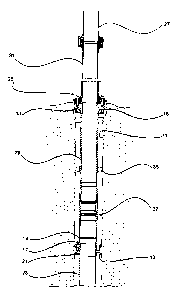
Figure 1 is a sectional elevation illustrating the mudline riser-casing
connecting
assembly according to the embodiment;
Figure 2 is a sectional elevation of the mudline riser casing connecting
assembly
according to the embodiment illustrating a drill rod accommodated within the
riser
and the well bore casing accommodating the mechanical disconnect tool;
Figure 3 is a sectional elevation of the mudline riser-casing connecting
assembly
according to the embodiment illustrating the disconnection of the riser from
the
upper end of the casing; and
Figure 4 is a sectional elevation of the mudline riser-casing connecting
assembly
according to the embodiment illustrating the mounting of a Christmas tree
assembly to the well for production purposes.
Detailed Description of Specific Embodiment
The embodiment is directed to a mudline riser casing connecting assembly
providing connection between the riser and the casing of an underwater well in
circumstances where the blowout preventer is at or about the surface of the
water. The embodiment serves to provide a connection between the riser and
casing which will accommodate for the suspension loads exerted by the casing
to isolate the suspension loads from the riser, whilst allowing for the
relative

CA 02373005 2002-02-25
-5-
movement of the riser without causing resultant movement of the casing within
the bore hole.
The embodiment comprises a borehole conductor casing 11 which is receivable
in a borehole. The borehole conductor casing 11 provides support for both the
riser 27 and the well bore casing 23 of the well. Such support is in part
provided
by a landing shoulder 13 which comprises an inwardly directed annulus provided
in the inner face of the bore hole conductor casing at a position spaced
downwardly from the upper end of the bore hole conductor casing. Support for
the riser is provided by an enlarged support housing 15 which is provided at
the
upper end of the bore hole conductor casing in the region of the mudline.
The mudline riser-casing connecting assembly further comprises a hanger 17
which is engageable with the landing shoulder 13 and which comprises a central
tubular portion 19 and an annulus 21 where the annulus 21 is adapted to be
engageable with the landing shoulder to prevent movement of the hanger 17
past the landing shoulder 13. The hanger 17 is adapted to be fixed to the
upper
end of the well bore casing 23 to enable the well bore casing 23 to be
supported
from the landing shoulder 13.
The upper end of the hanger 17 is engageable with a connector assembly 25
which extends between the hanger 17 and the lower end of the riser pipe 27.
The connector assembly comprises a first portion 29 which extends between the
hanger 17 and the support housing 15 of the bore hole conductor casing and a
second portion which comprises a tapered stress joint 31 located between the
upper end of the first portion 29 and the lower end of the riser 27. The upper
end
of the first portion is formed with an annular flange 33 which is receivable
with
the support assembly 15 of the support housing of the bore hole conductor
casing to be incapable of relative radial movement within the bore hole
conductor
casing 11. In addition, an annular stabiliser 35 is mounted to the first
portion to
be receivable within the bore hole conductor casing 11 at a position
intermediate
of the length of the first portion 29 to prevent flexure of the first portion
between
its ends.

CA 02373005 2002-02-25
- 6 -
The stress joint 31 is configured to accommodate for the relative movement of
the lower end of the riser 27 to the bore hole conductor casing and to
accommodate the stresses which are the result of such relative movement.
The lower end of the first portion 29 accommodates a mechanical disconnect
tool
37 which is of a substantially conventional form and through which the lower
end
of the first portion 29 can be remotely engaged with and disengaged from the
upper end of the hanger 17 whereby the riser can be disconnected from the
casing as illustrated at Figure 3 when it becomes necessary to decommission a
well and/or it becomes necessary for the rig associated with the well to move
out
of station.
The mudline riser-casing connecting assembly of the embodiment ensures that
no bending loads which are exerted upon the riser are transmitted to the
casing
below the mudline. Furthermore, the mudline riser-casing connecting assembly
provides a means of supporting the casing within the borehole from the mudline
in order to isolate the loading exerted by the weight of the casing from the
riser.
Furthermore, the embodiment enables the use by a semi-submersible drilling rig
of a blowout preventer located at or about the surface of the water by virtue
of its
capacity to accommodate the flexure of the riser. In addition, the embodiment
provides a means of selectively connecting and disconnecting the riser from
the
casing as required without permanently decommissioning the well. This is
enabled by the circumstance that the weight of the casing is accommodated by
the bore hole conductor casing. This latter feature enables the temporary
suspension of drilling and/or draw off activities from a well in the event
that the
supporting rig is required to move off station from the well. Furthermore, the
disconnect and reconnect facility enables an exploration well to be converted
to a
production well as required.
Throughout the specification, unless the context requires otherwise, the word
"comprise" or variations such as "comprises" or "comprising, will be
understood
to imply the inclusion of a stated integer or group of integers but not the
exclusion of any other integer or group of integers.

CA 02373005 2002-02-25
-7-
It should be appreciated that the scope of the present invention need not be
limited to the particular scope of the embodiment as described above.

Representative Drawing
A single figure which represents the drawing illustrating the invention.
Administrative Status

2024-08-01:As part of the Next Generation Patents (NGP) transition, the Canadian Patents Database (CPD) now contains a more detailed Event History, which replicates the Event Log of our new back-office solution.

Please note that "Inactive:" events refers to events no longer in use in our new back-office solution.

For a clearer understanding of the status of the application/patent presented on this page, the site Disclaimer , as well as the definitions for Patent , Event History , Maintenance Fee  and Payment History  should be consulted.

Event History

Description Date
Inactive: IPC from MCD 2006-03-12
Application Not Reinstated by Deadline 2005-02-25
Time Limit for Reversal Expired 2005-02-25
Deemed Abandoned - Failure to Respond to Maintenance Fee Notice 2004-02-25
Application Published (Open to Public Inspection) 2002-10-30
Inactive: Cover page published 2002-10-29
Inactive: First IPC assigned 2002-06-06
Inactive: First IPC assigned 2002-06-03
Inactive: First IPC assigned 2002-05-03
Filing Requirements Determined Compliant 2002-03-22
Inactive: Filing certificate - No RFE (English) 2002-03-22
Letter Sent 2002-03-22
Application Received - Regular National 2002-03-21

Abandonment History

Abandonment Date Reason Reinstatement Date
2004-02-25

Fee History

Fee Type Anniversary Year Due Date Paid Date
Application fee - standard 2002-02-25
Registration of a document 2002-02-25
Owners on Record

Note: Records showing the ownership history in alphabetical order.

Current Owners on Record
WOODSIDE ENERGY LIMITED
Past Owners on Record
DAVID F. BOND
KEVIN T. GALLAGHER
Past Owners that do not appear in the "Owners on Record" listing will appear in other documentation within the application.
Documents

To view selected files, please enter reCAPTCHA code :


To view images, click a link in the Document Description column. To download the documents, select one or more checkboxes in the first column and then click the "Download Selected in PDF format (Zip Archive)" or the "Download Selected as Single PDF" button.

List of published and non-published patent-specific documents on the CPD .

If you have any difficulty accessing content, you can call the Client Service Centre at 1-866-997-1936 or send them an e-mail at CIPO Client Service Centre.


Document
Description 
Date
(yyyy-mm-dd) 
Number of pages   Size of Image (KB) 
Representative drawing 2002-05-29 1 13
Abstract 2002-02-25 1 45
Description 2002-02-25 6 270
Claims 2002-02-25 3 139
Drawings 2002-02-25 4 132
Cover Page 2002-10-16 2 63
Courtesy - Certificate of registration (related document(s)) 2002-03-22 1 113
Filing Certificate (English) 2002-03-22 1 164
Reminder of maintenance fee due 2003-10-28 1 106
Courtesy - Abandonment Letter (Maintenance Fee) 2004-04-21 1 175