Note: Descriptions are shown in the official language in which they were submitted.
CA 02373218 2002-02-25
P98252 PATENT APPLeiCATION
FRETTED/FRE'TLESS STMGED MUSICAL xl'dSTRYJMENT
FIEI.D OF THE INV4WICIN
This invendon relates to stringed musical finsttvments of the type that may be
selectively played m the fretted and umfretted mode, and more particuiaicly to
means for
canvoorting such an instcument from one mode to the other without affectin,g
the playing
"action" of the instrument in terms of the distame each string must travel
when proesed
down to obtain the tuned pitch of a note in either the fibtted or unftetted
mode.
A sbua,ged muaical insbvnment is one having a aubatanii,aAy flat sound box
across
which sirings are strimg and a long neck comeeting the box to a uaiing head
whera pcgs
a:e mounted for tuning the individual strings. The strings pass oither over a
sound
opening on the front of the box or betweeus a pair of sound openings, for
example, or
simply pass over a sound transducer at or near the sarface of the box in the
case of an
electronic insbumoat, such as an alectronxc guitar. The instnanent is played
by
stinmmaing or plucking the strings with one hand while selecting the pitch of
a musical
note to be made by the strings engaged with the other hsmd by preeaing them
down at
selected positions along a fingerboatd on the neck, normally with only the
5ngers, hence
the term "Sngerboard..,,
In the ease of a fratless instrument, the Sngers press the seleoted suings
agaiast
the fingerboard at locations that will thcn eaaise the sbrings to produce
dcsired notek each
with a desired pitch, but in the case of a fretted iastnament, the f'agera
press the strings
agsinst selected lateral bars or freta spaced lonp,tudinally along the
fingerboard. In that
case, a pressed string produces a tone of a well defined pitch. Yn other
words. firets
infhuace the tonal chairaate,r of the pitch to be very sharp and cleairly
defsuod, whareas the
tonal charaeter of tite pitch prod.uced on a firotlesa fm,gerbosrd is softer
and less defined,
CA 02373218 2002-02-25
P98252 2
thus producing a more swolling type of sound. This is so becanse the point of
pre:ss ing
the string agWnst the fingerboard is not so well defined as in the case of
preesing the
string against a fret, the top of which is fixed to be above the surface of
the fmgerboard.
It is customary to use one or the othGr of tM fretted and Mess types of
instruments according to the nature of the musie to be played, but souaedxnes
it is
desirable to switch from one typc of instmxment to the other on the same
instxument in the
middle of the piece of music being played. Consequently, it would be desirable
to have
both options available in one instrument by providing some means for
effxtivel.y
removing the frats quickly at the option of the musician, sucb as by switcbing
a lever at
the instrnment head from one position to another, as shown in U.S. Patent No.
5,325,757.
That thooretieaUy makes it possible for playing the instrument altemately in
the two
modes, fratted and fretle:s. However, once the iashwnent sumgs are tuned in
the frettad
mode (while the tonal characteristie of the ingtrument is very sharp and
clearly defined),
that prior-art instrument responds well only while being played in the fretted
mode.
While playing that prior-art instrument in the uturetted mode, i.e., with the
ljrets
reUacted into the neck, the distsaee the stringe must travel increases when
pressed down
to obtain desired notes. As a result, the musiciim will find it more difScult
to press the
suiAgs in the unsretted mode in order to play desired notes. Furthermore, the
musician
will find that the pitch of the notes produced in the unfibtted mode increasea
from the
tuned pitch produced by the asme fin,ger position used while playing the
instrument in the
ftetted mode. In addition, the musician will neod to adjust the position of
the fingecs to
compenaate for the incrcaseJdecrease in pitch of the notes when switching
between the
two modes. The result is that the tttusician is pruented with an insvmuntable
"aetion"
problem.
2 s An object of this invention is to provide a frvtt,eid/fretless slring
instrument
without this "aation" problean so that the iaasttuentnt wiA allow rwitching
between its two
modes while playing the same piece of music.
CA 02373218 2009-10-26
65312-466
3
STATEMENT OF THE INVENTION
In accordance with some embodiments of the present invention, a
fretted/fretless string instrument is provided with means for switching
between its
-fretted and unfretted modes by rigidly securing the frets in the neck of the
instrument with the frets protruding through spaced slots in a separate
fingerboard
between the strings and the neck. That separate fingerboard, provided with
flanges extending over the sides of the neck, is implemented as a rigid board
having a slightly curved surface between its flanges as is customary for
string
instruments, and is supported over the neck by two rails, one over each
flange,
having inwardly protruding pins that fit into spaced slide slots in the
flanges. The
rails are in turn supported on the neck by spaced screws that pass through
horizontal slots in the rails and vertical slots in the flanges. The
horizontal screw
slots in the rails allow the rails to be driven back and forth relative to the
neck
while the vertical screw slots in the fingerboard flanges restrain the
fingerboard to
movement up and down relative to the neck as the rail pins protruding inwardly
into the slide slots are driven back and forth between end portions of the
slide
slots oriented parallel to the neck and a sloped portion between the parallel
and
offset end portions. The extent that the parallel end portions are offset from
each
other in a vertical direction with respect to the neck determines the limits
of up and
down movement up to a position flush with the tops of the frets for the
fretted
mode down to a position preferably near the neck with a predetermined space
between the neck and fingerboard. The advantage of this arrangement of raising
a separate fingerboard up, vis-a-vis the prior art arrangement of lowering the
frets
in a fingerboard integral with the neck, is that the distance the strings must
travel
while playing the tuned instrument in the fretless mode remains the same for
the
same notes with the same pitch as when the fingerboard is lowered for playing
in
the fretted mode, thereby avoiding the "action" problem of the aforesaid prior-
art
instrument noted above.
Thus, the separate fingerboard is provided with slots through which
'the frets protrude upwardly toward the strings for playing in the fretted
mode while
the separate fingerboard is in its lowered position, preferably a minimum
space
CA 02373218 2009-10-26
65312-466
4
away from the neck. For the fretless mode, the separate fingerboard is raised
so
that it is even with the tops of the frets. This second position of the
separate
fingerboard flush with the tops of the frets provides a fretless fingerboard
with a
play action indistinguishable from a fretted fingerboard, thereby allowing the
musician to play the instrument without an "action" problem.
According to one aspect of the present invention, there is provided a
stringed musical instrument having a neck, a body at one end of said neck and
a
head with pegs for tuning strings over said neck, said instrument intended to
be
alternately played in a fretted mode or an unfretted mode comprising: said
neck
having frets affixed thereto over which strings of said instrument are tuned
taut
with a virtually uniform spacing of said strings above a top surface of said
frets; a
separate fingerboard over said neck having slots for said frets to protrude
through
said fingerboard, said fingerboard positioned between said string and said
neck in
a position for playing said instrument in the fretted mode; and means for
selectively raising said separate fingerboard over said neck to a position
even with
said top surface of said frets in response to pivotal motion of a lever in one
direction for playing said stringed instrument in an unfretted mode and for
selectively lowering said separate fingerboard for playing said instrument in
a
fretted mode in response to a pivotal motion of said lever in a direction
opposite
said one direction; whereby spacing of said strings over said top surfaces of
said
frets remains constant for playing said instrument in both the fretted and
unfretted
modes.
The novel features that are considered characteristic of this
invention are set forth with particularity in the appended claims. The
invention will
best be understood from the following description when read in connection with
the accompanying drawings.
BRIEF DESCRIPTION OF THE DRAWINGS
FIG. 1 is a plan view of the neck and head of a stringed instrument
embodying the present invention, but without strings.
CA 02373218 2009-10-26
65312-466
4a
FIG. 2A is an exploded isometric view of the neck shown in FIG. 1
and FIG. 2B is a diagram of camming "slide" slots in side flanges of a
fingerboard
that is separate from the instrument neck.
FIG. 3A is a side view of the neck shown in FIG. 2A with the
fingerboard lowered for playing the instrument in the fretted mode.
FIG. 3B is a side view of the neck shown in FIG. 2A with the
fingerboard raised for playing the instrument in the fretless mode.
FIG. 4A is a longitudinal cross-section of the neck and fingerboard
shown in FIG. 3A now shown with a taut bass string over the frets, i.e., shown
in
the fretted mode.
FIG. 4B is a longitudinal cross-section of the neck and fingerboard
shown in FIG. 3B now shown with a taut bases string over the fingerboard and
the
fingerboard flush with the frets, i.e., shown in the fretless mode.
FIG. 5A is a lateral cross-section of the neck and fingerboard shown
in FIG. 4A.
FIG. 5B is a lateral cross-section of the neck and fingerboard shown
in FIG. 4B.
CA 02373218 2002-02-25
F90iSZ 5
DBTAILED DBSCRIPTIAN OF TSL YNVENTIQN
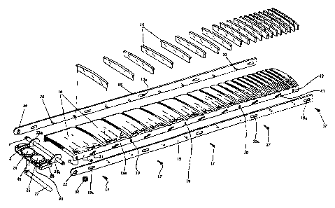
RefCrring to FIG. 1, the neck 10 of a stringed instrument is shown without a
body.
A laead 11 seaves to hold tuning pegs (not shown) for taut strings (also not
shown)
indicated to be four in number by the number of holes 12 for the pegs. The
number of
strings, which may vary dependi.ng on the particular type of instrument, is
not eritical to
the invention. The four strings Sl to S4 shown only in FIGs. 4A,B and SAB are
anchored at a position on the guitar body (not shown) on the far side of a
sound opening
relative to the nook and there hold away from the &ont of the body by a bar
secured on the
surface of the body. A bar 13 at the iiar end of the neck 10 proximate the
head 11 holds
the strings away fnom the neclt 10 sueh that they axe hcld a aet dismnce D
above frats 14
fixed in position on the neck 10 as shown in FIGL 4A-,,B and SA,B.
A rigid drive raa115, such as of aluminum, brass or plastic secured on each
side of
the neck to selectively position a t"ingerboard 16 implemented as a separate
strip of hard
wood or metal over the neck 10 in one of two selectable positions, up or down.
The down
position is flat almost against the neck with a minimum gap G, as shown in
FIGs. 4A and
SA, with the frets 14 protntdmg tln+ough slots 16a in the fingerboard 16, as
shown in
FIG. 2A. The down position is hereinafter raferrod to as the position of the
fingerlward
for the frettod mode of playing the instrument. The up position is with the
surface of the
fingerboard raised a distance H to a position flush with the top surfaees of
the frets 14, as
shown in FIGs. 4B and SB. That up position is haeinaffter ref;cmod to as the
position of
the fingerlward for the fretless mode of playing the instrument. This
arrangement of the
&ats 14, two rails 15, and a separate fugerboard 16 may be bctter understood
from the
following dascription with refeamce to the exploded view in FIG. 2A.
Flanges 16b on both sides of the fingerboard 16 are provided to fit along tlie
sides
of the neck 10, as best shown in the crass-sectionai views of ft neck in FIGs.
sA snd
SB, and to hold the fingerboard poaitioned over the neck by retaining screws
17 that pass
through vertical slots 19 in the flanges 16b. The screws 17 also pass throug,h
horizontal
CA 02373218 2002-02-25
F98252 6
slots xSa in the drive rails 15 oriented parallel to the length of the drive
rail and therefoxe
pacallel to the neck 10 and fingarboad 16 so that the two drive rails 15 may
slide back
and forth on the retaiaing scxcws 17 in the longitudinal diresrtion of the
neck 10 but not in
a direction perpendicular thereto. The slots 1Sa of the rails 15 are
countersunk to allow
the heads of the retaining screws to be flush with or below the suzface of the
rails 1S.
The rail retaining screws 17 also pass through vertical slots 19 in the
fingerboard
flanges 16b to reach the supporting neck 10. The vertical orientation of the
slots 19 allow
the fiangmboard 16 to move only in a diroction perpeadicular to the neck 10
and the two
drive rails iS. The separate fifingerrboard 16 is thus constrained from moving
horizontally
along the neck 10 by the rail retaining screws 17 passing through the vertical
slots 19 in
the fingarboard flanges 16b.
"1'he position of the separate fingetboard 16 (up or down) on the neck 10 is
controlled by pins 20 which protrudc inwardly from the two drive rails IS into
"slide
slots" 21 in the fiagerboard flanges 16b. These slide slots are so named
because their
shape resembles the shape of a slide found on children's playgrounds, as
viewed ram the
side,. with horizontal end poartions parallel to the two rails 15 and a sloped
portion
between the end lrortions as shown in FIG. 2B. As the drive rails 15 are
driven in unison
back and forth, guided by their horizontal slots 1Sa. the pins 20 protruding
into the slide
slots 21 cam the fingerboard up and down on the neck 10 as the pins are driven
in the
slide slots alternateXy to the left and right end potions as viewed in FIGs.
2A and 2B .
The dianaeteor of the pins 20 is setected for a close fit in the slidc slots
of horizontal length
L as shown in FIG. aB, and the lengtb of the pins 20 is ohosen to just enp,ge
the sli.de
slots 21 in the flanges of the fingerboard 16 such that, while the drive rails
15 move
horixoatally back and forth, the fingerboard is cammed up and down by thc pina
20 in the
slide slots 21 in the fingerboard flanges 16b.
For axample, if the pins 20 are in the upper right end portion of the slide
slats 21,
the pins hold the fingdrboard 16 down so that its snface is below the top
surface of the
CA 02373218 2002-02-25
T702S2 7
freta 14 leaving a miwimum gap G berwoen the neck 10 and tM fingarbaat+d 16,
as
shovvn in FYG. 4A, thus presenting a fttted i.nshument to be played. This
ndnimum pp
G is pmvided to prevent the possibility of the fcngerboard cluitacing agaiaat
ft neck
wbile the strWgs are pkppd.
To chan;ge the froftd inastrwmsnt to be plaired in the uofi+eW tnodk, t6e
drive
rails 15 are moved to the leR, as viaaai in FIG. 2A, causing the pins 20 in
the slide slots
21 to cam the fingmboard 16 up as the pins move from the upper right aW
portiom of
the slots 21 to tiw lowa left portions of the slots, thus raising the
fiuprboard 16 flush
with the top stufaoos of the $+ete-. Bamuso the s"cm 17 pavant borisonial
motion of the
flngmboatd 16, thc only motion of the Singerboard is vertical to ft position
show+n in
FIG. 4B and FIG. SB. The reverse (downward) camming acaion of the pins 20
protruding io ft slide slots 21 in ft fin$aboard flanges 16b is obtained by
driving the
rails to thc right as vievrad in I+'iG. ?A.
The meaas for driviaQ the drive rails back and foA oompcises a fust raclc 23
and
purion 24 and a second ras:lc 23 and pimion 26 with the two piiuiom meahcd
togetleir saoh
that, when a levw 27 (connecbed to the piaion 24 through a shaft 26) is tvned
counterclockwise, the piuion 24 is tiuned countercloekvvise and its rack 23 is
drivan back
away fivtq the f ngcrboard 16. The pinion 24 in turn drives ft ma"d piniOn 26
clockwise to drive its rack 25 back in the satne direction as the rwk 23. Both
raclcs lfias
driven in unison ara c.oasaected to a traasvarse Gvtawting rod 29 which passca
through
holes in tabs 23a and 23a comootied lo the respective racka 23 and 23 and
throug,b a hole
in the raar end of oach of the rails 15 to assure that they too movIS in
uniscn in order to
drive rails 15 with the pins 21 on both sides of the mpamto iiingerboad 16
baok $+om a
hi,gh pcndoai of slide slots 21 in the Sngerboard flan,p l6b as shown un FIG.
3A and
down a sloped portion iaAw a low pordan of the slidc slots 21 as shwwn in FIG.
3B. In
*Aat mannu, the fingerboard is eammed upwsrdly, i.e., raised from iRs down
pcwition
shown in P'iGs. 3A and 4A vyith frots 14 protruding tbrough alots 16a in the
$ngahoerd
CA 02373218 2002-02-25
F90252 8
16, to its up position shown in FxG:. 3B and 4B with its fingorboard 16
swrface eveaa with
the tops of the firu 14, thus convmtimg the iashvrnant from the hvtted mode to
the
fretless mode. 'VVhp4 the leveor is tnraed back from the position shown in
I+IG. 3B to the
position shown in FIG. 3A, the camming action is reversed and the fiagerboard
is driven
from the up position in FIG. 3B to the down position in FIG. 3A- for again
playing the
instivmotent in the frelted mode. This can be done deftly without skipping a
beat in the
music being played by quickly nnanipulating the laver 27 using the hand on the
neck and
fingerboard
Attention is now direc.yted to the lowcred position of the fngerbonrd 16 shown
in
the crosa-sectional viows of the neck 10 in FIG. 4A and SA. Thece a aminamum
gsp G is
shown between the fingaboard and neck not only to illustrate that the former
is sepArate
from tbe latter but also to emphasize that a muumum gap is nccessaYy to avoid
any
vibration of the fingarbosrd agauxst the neck, as noted heoroinbefore. Also
shown is a
distance D between the strings (represeated by the single string 84) and the
fingerboard
Wace. When the fiagesboazd ] 6 is raised as shown in FIG. 4B, the gap G
increases by
the distance il #l7at ft fingerboard is raised, but t'he string distance D
remsins the swne.
In that mar.ner, raisiag the fingerboard to convert the instrunient to the
unftatted mode of
play instead of lowarin,g the frets as in the pxior art patent referanaod
hereinbefore, the
"action" problem is obviated by this invmdon maiataining the distance D the
seane for
both the fretted and unfretted modes of playing the instrument.
In practice, the space G in the fretted mode is minimized by millin,g the
slide slots
21 in the fingerbosrd ilutges so that the fingaorboard 16 almost rests on the
neck 10 leav-
ing the minimum gap G. This requires the rack and pinion assembly mounted on
the
hsadstock 30 of the neck 10, as shown in Y+1G. 3A, with a truavarse
c.oxmeating rod 29
between ft two rails 1s and the two raelcs 23,25 to be cormected with
preoisian to the
ends 22 of the two rails. That connecting rod 29 may be iamplemented with a
nut and bolt,
or with a shaft tlueaded at both ends for receiving nuts, only one nut 32
being shown ia
CA 02373218 2002-02-25
F98252 9
FIG. 2A,
To faeilitabe aseembty of the two racks and pinions with the pinion teCth
meshed,
a U-shaped brwket 33 is employed to secure the racks 23 and 25 to the sides of
that
bracket in a meshed position relative to the respective pinions 24 and 26 with
tabs 23a
and 25a between the rwks and the sides of the btacket. These tabs 23* and ZSa
may be
made integral with the racks 23 and 25, or separate as shown. In the laiter
aaee, they aro
to be fused or welded to their racks so that they move back and fortla as the
raeks are
driven in unison by the meshed pinions 24 snd 26.
Because of the importance of maxntaining the distattce H of the instrumont
strings
above the frets 15 and of maintaaning a minimum gap G betwean the fuigaboard
and the
neck, the usual truss rod T shown in FIGt. 4A,B an,d FIGs. SA,B is relied upon
to
compensate for any tendeticy of the neck to bend undar the force of the taut
8tcinga In
addition to that, graphite rods R are embedded in the neck on both sides of
the tnus rod
T, as shown in FIGs. 3A,SB.
in sunmtnary, the csxnmmg action required for rai-sing and lowering the
fIngerbosrd
for switching the raode of play from fretted to wa!'retted and vice versa is
sahieved by
manuaUy pivoting a lever to turn one of two meshed pinions in rack-and-pinion
assemblies for driving in unison two drive rails, one on each side of the
fingerboerd
adjacent to the two flmges on the sides thereof The flanges ame held onto the
neck of the
insftMeat along its two sides by setews thmugh horizontal slots in the drive
rails and
vertical slots in the flanges, whare the terms "verticsl" and "boxazontal"
define the
orientation of the slots relative to the neck of the instrument. Those screws
through
verti.cal slots in the fingerboaxd IIan$es and the frets pretuiding through
slots in the
Sagecboard hold the position of the fingerboard in its horizontal position
over the necJc
while the horizontal slots for those screws allow the drive rails to move back
and forth
horizontally over the f a,garboard tlanges.
The fingerboard flanges have slide slots spaced along their length and the
drive
CA 02373218 2002-02-25
P98252 10
rails have spaced pins protruding iawattiily into the slide slots. The side
slots are ahaped
to have horizontal end portions with a sloped poriion betrwoan thosc end
portions.
Cor~seque~tly, as the drive raiis are driven back and forrh over the
fingQrboard flanges,
the pins are dtiven back and forth over the sloped portions between the slide-
slot end
portions. In that msnner, the drive-rail pins cam the fingerbosrd up and down
over the
inetivmerrt neck while the Sngerboad is held in its horizontsl position over
the neck by
the screws in vertical slots of the 8in,gerboard slots and the frets
pzohuvding through the
slots in the fingerboard batween the flanges. The wtent of the thrust of the
drive rails.
limited by their horizontal slots for the screws, is sufficient to dtive thc
pins in the slide
1o slots of the fingerboard flanges between the two ead portions of the slide
slots. The
vertical spacing between those two end portions of the flange slide slots tlm
de5ne the
height (the extent) of the up and down casnming of tbe :6ngwboard. All
elements
involved in this cammixag ection mre coortlinated in aaenming the fusgerboazd
betvveen its
up position even with the tops of the frets and its down position with a
minimum gap
betweai the fingetboard and the neck. Those two up and down positions we set
by the
length and height of the fingerboard flange slide slots in coordinetion with
the vertioal
slots in the flanges for the fingerboard tiokding screws.
Although particular emboclnonents of the invention have beeri descsibed and
illustrated herein, it is recognized that modifications may readily occur to
those skilled in
the art. Conseques-tly, it is intended that the claims be intadcpreted to
cover aaalt
modifications azui equivalents theareof