Note: Descriptions are shown in the official language in which they were submitted.
CA 02373418 2001-11-09
WO 01/66220 PCT/GBO1/01065
_1_
METHOD AND APPARATUS FOR INTRODUCING A MOVING
LIOUID INTO A LARGER MASS OF MOVING LIQUID
The present invention relates to a method and apparatus for introducing a
moving liquid
into a larger mass of moving liquid, and most particularly to the introduction
of a stream
S of liquid carrying suspended solids (e.g. biocontaminated water) into a
larger moving
mass of such liquid in a vortex separator for removal of the solids.
The introduction of a moving liquid into a larger mass of moving liquid is
known to
have attendant difficulties. Turbulence and other disruptive forces can result
if the
introduction is not performed in an efficient manner, and unless care is taken
the liquid
to be introduced can be forced back along an inlet duct or the like.
Furthermore, the
efficiency of introduction can vary according to the inflow rate, the speed of
movement
of the larger mass of liquid, the density of the liquids and other variables.
The domestic or commercial keeping of fish and other aquatic life in tanks
results in
continuous contamination of the water with organic matter. Furthermore, the
water in
swimming pools, ponds, water-holding tanks and garden water features is
susceptible
to contamination by organic matter such as algae growth and dead plant matter.
It is
inconvenient and expensive to completely change the water on a daily basis.
Recirculating filter systems are conventionally employed, whereby water is
withdrawn,
the suspended solids are removed, and the cleaner) water is returned.
The removal of such suspended solids is conventionally achieved by a variety
ofknown
methods, including gravity separation, vortex separation, membrane filtration,
porous
block filtration, trickle tower filtration and combinations thereof. The
present invention
relates particularly to vortex separation.
Figures 1 and 2 of the accompanying drawings show respectively a front
perspective
view and an interior perspective view of an example of a known vortex
separator for use
in removal of suspended solids from a liquid.
CA 02373418 2001-11-09
WO 01/66220 PCT/GBO1/01065
-2-
The liquid is fed (e.g. under gravity) into a vortex chamber via an inlet port
1. The
vortex chamber has a curved internal wall surface 2, and the inlet port 1 for
the liquid
penetrates this curved internal wall surface 2 and is arranged to cause the
liquid to enter
the chamber substantially tangentially to the curve of the wall surface. The
curved
internal wall of the chamber has a longitudinal axis 3 which in use is
orientated
S generally vertically. The base of the chamber is closed by an end wall 4,
which defines
a conical hopper where the separated solids collect, and the top of the
chamber is
closable by a removable lid S (shown removed in Figure 2).
The curved internal wall surface of the vortex chamber causes the liquid
introduced into
the chamber to follow a curved path defined by the curve of the wall surface.
This
rapidly establishes a vortex in the liquid within the chamber, with a so-
called boundary
layer at the wall surface, in which boundary layer the frictional effects of
the wall
surface are substantial and the fluid flow differs from the bulk of the liquid
in the vortex.
The effect of the boundary layer causes a concentration of the solids towards
the base
of the chamber and a corresponding at least partial clearing of the water
towards the top
of the chamber.
An outlet port 6, penetrating the internal wall surface 2, is provided to
convey the
cleaner) liquid from the vortex chamber. The outlet port 6 is provided
somewhat above
the inlet port l, and is preferably arranged tangentially to the curve of the
wall surface
2.
The end wall 4 of the chamber is provided with a solids discharge port 7 and
an
associated valve, whereby the concentrated solids can be removed.
If desired, two or more vortex separators may be connected in series, to
handle larger
volumes ofwater. Vortex separators are conventionally employed with other
separators
such as filter or trickle tower separators, whereby the cleaner) outflow
liquid from the
vortex separator is fed directly to the filter or trickle tower separator for
further
treatment. Alternatively or additionally, porous absorbent and/or nitrifying
bacterial
CA 02373418 2001-11-09
WO 01/66220 PCT/GBO1/01065
-3-
media such as reticulated ether material (REM) foam cartridges can be located
within
the vortex chamber to assist purification of the water.
Examples of such conventional vortex separators for use in aquaculture, pools,
ponds
etc include the TASKMASTER and FLOWMASTER systems marketed by Nitritech
of Bristol, LJK (tel: +44 1454 776927; fax: +44 1454 250753).
The known vortex separators are efficient and relatively inexpensive systems
providing
a reasonable degree of removal of solids from liquids. However, there remains
a
continuing need for improvements and a continuing research effort to find
them.
The present invention is based on the surprising finding that, by configuring
an inlet port
so as to have a substantially rectangular cross-section and by arranging it so
that an
introduced liquid enters the larger moving mass of liquid at an internal wall
surface of
the container for the larger mass of liquid (e.g. the vortex chamber or other
apparatus
1 S containing the larger mass of liquid) at a sufficiently small angle (e.g.
up to about 40°,
preferably up to about 30°, and most preferably up to about 20°)
to the direction of flow
of the larger moving mass of liquid that the introduced liquid is
substantially maintained
in the boundary layer of the larger mass of liquid at the internal wall
surface, a markedly
improved efficiency of introduction is achieved, leading in the case of a
vortex separator
to a markedly improved efficiency of removal of solids.
The present invention may be stated generally to provide in a first aspect a
method for
introducing a moving liquid into a larger mass of liquid moving in an
apparatus
(including a duct), the method comprising introducing the first moving liquid
into the
second via an inlet port which penetrates an internal wall surface of the
apparatus, the
inlet port having a substantially rectangular cross-section and being arranged
so that the
introduced moving liquid enters the larger moving mass of liquid at the
internal wall
surface at a sufficiently small angle (e.g. up to about 40°, preferably
up to about 30°, and
most preferably up to about 20°) to the direction of flow of the larger
moving mass of
liquid that the introduced liquid is substantially maintained in the boundary
layer of the
larger mass of liquid at the internal wall surface.
CA 02373418 2001-11-09
WO 01/66220 PCT/GBO1/01065
-4-
In a second aspect the present invention may be stated generally to provide an
apparatus
(including a duct) adapted to contain a relatively large mass of liquid moving
therein,
and to permit a relatively small mass of moving liquid to be introduced into
the
relatively large mass, the apparatus having an internal wall surface and
comprising an
inlet port for the liquid to be introduced, the inlet port penetrating the
internal wall
surface of the apparatus, wherein the inlet port has a substantially
rectangular cross-
section and is arranged so that in use the introduced moving liquid enters the
larger
moving mass of liquid at the internal wall surface at a sufficiently small
angle to the
direction of flow of the larger moving mass of liquid that the introduced
liquid is
substantially maintained in the boundary zone of the larger mass of liquid at
the internal
wall surface.
The phrase "substantially rectangular cross-section" used herein refers
particularly to
a generally elongate slot-like inlet port. Thus, the phrase is intended to
define not only
a true rectangle but modified rectangles, for example trapezoids or ports
having curved
sides, so long as the general form of an elongate slot is preserved. The
dimensions and
configuration of the substantially rectangular cross-section of the inlet port
will be
readily selected by one of ordinary skill, having regard to the intended
capacity of the
system and the intended flow rate of liquid. The short dimension of the
rectangle should
not, however, generally be substantially greater than the thickness of the
boundary layer
of the moving liquid in the apparatus in use. This thickness can readily be
measured
experimentally, as is well known to one of ordinary skill. In general, the
larger the short
dimension of the rectangle, the smaller must be the angle of incidence of the
introduced
liquid into the larger mass of liquid. Typically, the ratio of the longahort
sides of the
rectangle will be in the range of about 3:1 to about 15:1.
It is preferred that the long axis of the rectangle is aligned substantially
transverse to the
flow direction of the larger moving mass of liquid.
It is preferred that the general (curved) plane of the internal wall surface
is not disturbed
by extensions or protruberances in the region of the inlet port.
As stated above, the present invention is particularly applicable to vortex
separators.
CA 02373418 2001-11-09
WO 01/66220 PCT/GBO1/01065
-5-
Thus, in a third aspect the present invention may be stated generally to
provide a vortex
separator for use in at least partially removing suspended solids from a
liquid, the vortex
separator comprising:
(a) a vortex chamber having (i) a curved internal wall surface which has a
longitudinal axis which in use is orientated substantially vertically, and
(ii)
an end wall closing a base of the chamber;
(b) an inlet port for the liquid, which inlet port penetrates the curved
internal
surface of the vortex chamber and is arranged to cause the liquid to enter the
chamber substantially tangentially to the curve of the wall surface;
(c) an outlet port for the liquid, which penetrates the curved internal wall
surface
and is arranged to convey the liquid from the chamber after at least some of
the suspended solids have been separated from the liquid; and
(d) a discharge port for the suspended solids;
wherein the inlet port has a substantially rectangular cross-section at the
internal wall surface of the chamber.
By arranging the inlet port so that the liquid enters the vortex chamber
substantially
tangentially to the curve of the wall surface, the angle of incidence of the
introduced
liquid entering the moving mass of liquid in the vortex chamber will be
sufficiently
small (e.g. no more than about 40°, preferably no more than about
30°, and most
preferably no more than about 20°, in view of the typical radius of
curvature found in
vortex separators) that the introduced liquid is substantially maintained in
the boundary
zone of the liquid in the chamber in use, which covers the inlet and outlet
ports.
As mentioned above, the dimensions and configuration of the substantially
rectangular
cross-section of the inlet port will be readily selected by one of ordinary
skill, having
regard to the intended capacity of the system and the intended flow rate of
liquid. Thus,
for example, in a vortex separator having a chamber capacity of between about
0.5 and
CA 02373418 2001-11-09
WO 01/66220 PCT/GBO1/01065
_6_
about 1.5 cubic metres and an optimum liquid through-flow rate ofbetween about
7 and
about 13 cubic metres per hour, a substantially rectangular inlet port having
a ratio of
the longahort sides of about 7:1 and a cross-sectional area of about 100 to
about 220
cm2, preferably about 150 to about 200 cm2 will be suitable. The long side may
suitably
be between about 20 cm and about 50 cm in length, preferably about 35 cm, and
the
short side may suitably be between about 1 cm and about 10 cm in length,
preferably
about 5 to about 8 cm. The short side length represents the transverse width
of the inlet
port; as the inlet port penetrates the curved internal wall surface of the
vortex chamber,
the circumferential length of the short side will increase, typically by a
factor of
between 1.5 and 2.5, compared with the said transverse width.
As mentioned above, in vortex separators of this type the inlet port is
located below the
level of the outlet port. The inlet port of the vortex separator according to
the present
invention preferably penetrates the internal wall surface of the vortex
chamber over a
top or bottom length corresponding to the majority (i.e. at least 50%) of the
lower half
of the chamber. The top of the inlet port should, however, still be below,
preferably
substantially below, the outlet port. The outlet port correspondingly should
be
positioned well within the upper half of the chamber. All the ports are
submerged when
the vortex separator is in use.
To perniit the vortex separator to be connected to conventional pipework for
liquid flow,
a circular-to-rectangular adaptor system is preferably provided, communicating
with the
inlet port through the curved wall of the chamber and extending to the
exterior of the
chamber to end in a circular cross-sectional shape adapted for connection to
conventional circular pipework and the like. The cross-sectional areas of the
two ends
will typically be chosen so that the rectangular area is not substantially
smaller than the
circular area, so as not to constrict any liquid flow between the circular and
rectangular
ends. Thus, for a vortex separator having the dimensions specifically
mentioned above,
the radius of the circular end will be in the range of about 4 to about 10 cm,
preferably
about ~ to about 8 cm.
In one arrangement, the circular end of the adaptor system may be
substantially
horizontally level with the top of the substantially rectangular inlet port
(as in use), as
CA 02373418 2001-11-09
WO 01/66220 PCT/GBO1/01065
this configuration has been found to give a smooth liquid flow through the
adaptor
system and the inlet port.
In an alternative arrangement, the circular-to-rectangular adaptor system may
compnse
a circular inlet pipe which enters the base of a tank disposed exteriorly of
the wall of the
vortex chamber. The tank is preferably open to the top and covered by a lid in
use. In
this arrangement, the substantially rectangular inlet port is formed as a
substantially
rectangular aperture penetrating the wall of the vortex chamber from the tank
at the level
of the bottom of the tank, thereby providing fluid flow connection between the
tank and
the vortex chamber.
The tank serves as a header tank to smooth out fluctuations in the inlet flow
rate of
contaminated fluid and to reduce the fluid flow rate if an upstream feeder
pump is being
used. The smoothing/reduction of the inlet flow rate can provide for optimum
vortexing, as high pressure bursts of the inlet fluid can easily disrupt the
vortex in the
vortex chamber.
For ease of manufacture of this separator arrangement, and to facilitate
stacking of the
separators for storage and transportation, that portion of the wall of the
vortex chamber
which lies above the inlet port and between the vortex chamber and the tank is
suitably
made to be removable. In one preferred form, the removable wall portion tapers
inwardly in the downward direction and is seated on correspondingly tapered
formations
of the internal wall surface of the vortex chamber. To assist in guiding the
parts into
seating engagement, and to retain them in position for use, cooperating pairs
of rib and
recess formations are suitably provided on the meeting surfaces.
The circular end of the circular-to-rectangular inlet adaptor system is
suitably provided
with a spigot, flange or other conventional connector piece, whereby external
pipework
can be push, screw, bayonet, snap or otherwise fitted to the adaptorpipe in
conventional
manner. The circular end of the circular-to-rectangular inlet adaptor system
of the
separator may be provided with a valve, e.g. a slide valve, so that the
separator may be
isolated from any upstream feed pipework, pumps, etc. in an emergency. The
outlet and
CA 02373418 2001-11-09
WO 01/66220 PCT/GBOI/01065
_g_
discharge ports are suitably provided with connector pieces selected from the
conventionally available range.
The vortex separator according to the present invention may be manufactured
out of any
suitable materials. Most preferred are plastics such as polyethylene (e.g.
HDPE) or
polypropylene. The materials may, if desired, be reinforced, e.g. by glass
fibres. The
vortex separator, including the adaptor pipe, is suitably moulded as a unit,
the lid being
constructed as a separate item adapted to rest or fit (e.g. snap or push fit)
onto the rim
of the vortex chamber. The lid is suitably moulded from the same material as
the vortex
separator itself.
10.
The vortex separator is suitably mounted in use on a pedestal base, which
supports the
vortex chamber. This pedestal base may be integral with the vortex separator
or may
be constructed as a separate item. The pedestal base is suitably moulded from
the same
material as the remainder of the separator.
The present invention provide substantial advantages in terms of operating
efficiency.
Without wishing to be bound by theory, it is believed that the configuration
of the inlet
port enables the introduced liquid to be delivered more efficiently into the
(slower
moving) boundary layer of the relatively large mass of liquid, in which in the
case of a
vortex separator the most efficient separation of contaminants is believed to
occur.
However, the invention is not to be considered as restricted by this
theoretical
possibility.
For ease of understanding of the present invention, and to show how the same
may be
put into effect, embodiments will now be described, purely by way of example
and
without limitation, with reference to Figures 3 to 13 of the accompanying
drawings, in
which:
Figure 1 shows a front perspective view of the known vortex separator, as
described
above;
Figure 2 shows an interior perspective view of the known separator of Figure
1;
CA 02373418 2001-11-09
WO 01/66220 PCT/GBOi/01065
-9-
Figure 3 shows a front elevation view of a vortex separator according to the
present
invention;
Figure 4 shows a side elevation view of the vortex separator of Figure 3;
S
Figure 5 shows a top view of the vortex separator of Figure 3;
Figure 6 shows an interior perspective view of the chamber of the vortex
separator of
Figure 3;
Figure 7 shows a perspective side view of an alternative vortex separator,
according to
the invention;
Figure 8 shows perspective detail of part of the interior wall of the vortex
chamber of
the separator of Figure 7, in the region of the inlet port, showing the
removable wall
portion;
Figure 9 shows perspective detail of the inlet port of the separator of Figure
7 from the
upstream side, showing the relationship with the upstream header tank and the
inlet
connector pipe;
Figure 10 shows the distribution of residence times for synthetic fish waste
in
comparative tests on the separators of Figures 1 and 2 ("G") and 3 to 6 ("B");
Figure 11 shows the directional convention employed in the comparative tests;
Figure 12 shows the distribution of measured residence times of the synthetic
fish waste
in the comparative tests, from which mean residence times are calculated; and
Figure 13 shows the distribution of measured settling velocities of fish waste
in
comparative tests on real ("F") and synthetic (plastic beads) ("P") fish
waste.
CA 02373418 2001-11-09
WO 01/66220 PCT/GBO1/01065
-10-
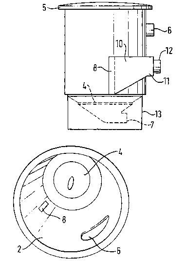
Refernng firstly to Figures 3 to 6, in which like parts are designated as in
Figures 1 and
2, there is shown a vortex separator for use in removing suspended solids from
water.
The vortex separator comprises a vortex chamber which in use receives the
water via an
inlet port 8. The vortex chamber has a curved internal wall surface 2.
As illustrated, the inlet port 8 has a substantially rectangular cross-section
at the internal
wall surface and is arranged to cause the water to enter the chamber
substantially
tangentially to the curve of the wall surface.
The curved internal wall of the chamber has a longitudinal axis 3 which in use
is
orientated generally vertically. The rectangular inlet port 8 has a long axis
which is
aligned substantially parallel to this longitudinal axis 3 of the curved
internal wall, i.e.
substantially transverse to the direction of flow of water in the vortex
chamber when the
separator is in use and the ports are submerged.
The base of the chamber is closed by an end wall 4, which defines a conical
hopper
where the separated solids collect, and the top of the chamber is closable by
a removable
lid 5 adapted to rest on a rim 9 of the vortex chamber.
To permit the vortex separator to be connected to conventional pipework for
liquid flow,
a circular-to-rectangular adaptor pipe 10 is provided, communicating with the
inlet port
8 through the curved wall of the chamber and extending to the exterior of the
chamber
to end in a circular cross-sectional shape 11 provided with an end spigot 12
for
connection to conventional circular pipework and the like. The cross-sectional
area of
the rectangular (inlet port 8) end of the adaptor pipe 10 is no smaller than
the cross-
sectional area of the circular end 11, so that no constriction of the water
flow is caused.
The circular end 11 of the adaptor pipe 10 is substantially horizontally level
with the top
of the rectangular inlet port 8.
The vortex separator is provided with an outlet port 6 which penetrates the
internal wall
surface 2, to convey the cleaner) water from the vortex chamber. The outlet
port 6 is
CA 02373418 2001-11-09
WO 01/66220 PCT/GBO1/01065
-11-
located somewhat above the inlet port 8, and is arranged so that the water
exits the
vortex chamber tangentially to the curve of the wall surface 2.
The end wall 4 of the chamber is provided with a conventional solids discharge
port 7,
whereby the concentrated solids can be removed.
The vortex separator is mounted in use on a pedestal base 13, which supports
the vortex
chamber.
All parts are preferably formed in moulded plastic materials, the lid 5 and
the pedestal
base 13 being separable from the remainder (although the pedestal base 13 may
alternatively, if desired, be integral with the separator).
Referring now particularly to Figures 7 to 9, an alternative separator is
shown, in
accordance with the present invention. Like parts are designated in like
manner to
Figures 1 to 6.
The primary difference between the separator of Figures 3 to 6 and that of
Figures 7 to
9 lies in the construction of the inlet port 8 and the fluid feed apparatus
immediately
upstream of the inlet port 8. As shown particularly in Figures 7 and 9, the
circular-to-
rectangular adaptor system immediately upstream ofthe inlet port 8 comprises a
circular
inlet pipe 14 which enters the base of a tank 15 disposed exteriorly of the
wall of the
vortex chamber and open to the top. The tank wall extends to the same top
level as the
wall of the vortex chamber, as shown in Figure 7. In use, the lid of the
separator (not
shown) is shaped to fit over both the vortex chamber and the tank 15.
The rectangular inlet port 8 is formed as a rectangular aperture penetrating
the wall of
the vortex chamber from the tank at the level of the bottom of the tank 15,
and thereby
providing fluid flow connection between the tank and the vortex chamber.
The tank 15 serves as a header tank to smooth out fluctuations in the inlet
flow rate of
contaminated fluid and to reduce the fluid flow rate if an upstream feeder
pump is being
used. The smoothing/reduction of the inlet flow rate can provide for optimum
CA 02373418 2001-11-09
WO 01/66220 PCT/GBO1/01065
-12-
vortexing, as high pressure bursts of the inlet fluid can easily disrupt the
vortex in the
vortex chamber.
For ease of manufacture of the separator in molded plastics, and to facilitate
stacking of
the separators for storage and transportation, that portion 16 of the wall of
the vortex
S chamber which lies above the inlet port 8 and between the vortex chamber and
the tank
15 is made to be removable. In the illustrated arrangement, shown particularly
in Figure
8, the wall portion 16 tapers inwardly in the downward direction and is seated
on
correspondingly tapered formations of the internal wall surface 2 of the
vortex chamber.
To assist in guiding the parts into seating engagement, and to retain them in
position for
use, cooperating pairs of rib 17 and recess 18 formations are provided on the
meeting
surfaces.
A conventional slide valve 19 is provided, associated with the circular inlet
pipe 14,
which can serve to isolate the separator from upstream pipework, pumps and
other
apparatus, in the event of an emergency. The valve slide 20 is shown partially
closed
in Figure 9.
Comparative Trials
The following report of comparative trials measuring the separation efficiency
and other
performance of the apparatus of Figures 1 and 2 (the so-called "green bin")
against the
apparatus of Figures 3 to 6 (the so-called "black bin") is included for
further information
and to illustrate the advantages of the present invention (the so-called
"fishtail" inlet
port).
A. Residence Time and Separation Efficiency Tests
For health and safety reasons, real fish waste could not be used for this
testing, so an
alternative material (plastic beads) was found. Please refer to Section E
below, for full
details.
CA 02373418 2001-11-09
WO 01/66220 PCTlGBOI/01065
-13-
Al. Aim
The aim of this set of tests was to compare the old (green) separator with the
new
(black) separator and to identify whether one performed better than the other.
This was
done by comparing residence time and separation efficiency.
Residence time was defined as the time between the beads entering the chamber
and
passing down over the rim of the conical hopper of the end wall 4 of the
chamber, the
"rim" being the region of the hopper indicated as 4a in Figures 2, 3, 4 and 6,
which is
a small vertical portion of the hopper wall about half way up the hopper. The
rim was
chosen as the exit point because any beads that were seen to fall over the rim
systematically settled, whereas beads that passed near it and even touched the
surface
of the hopper above the rim were occasionally seen to rise back up into the
main flow
of the vortex.
The main objective of this part of the testing was to identify with a 95%
confidence
level whether the new black separator had a mean residence time at least 1
second less
than the old green separator. Further details of the design of experiment
associated with
this objective are described in Section F below.
A small proportion of the beads that entered the chamber then left with the
rest of the
effluent via the tangential outlet. In order to ensure that this quantity did
not change
considerably with the new design, separation efficiency, rls~P was measured as
function
of the mass of beads leaving and settling in the separator:
7ZZsettled
7Jsep =
7ZZsettled -~ lZZexit
The second objective of this testing was to ensure that any improvement in
residence
time was not coupled with a loss in separation efficiency.
CA 02373418 2001-11-09
WO 01/66220 PCT/GBO1/01065
-14-
AZ. Experimental set-up
The vortex chamber was filled to within 2 cm of the top and the solids
discharge port
7 closed. The tangential effluent outlet port 6 was cormected to a pump inlet
(not
shown) via a flexible hose. A fine mesh filter at the pump inlet caught any
beads that
S left the vortex chamber. The pump outlet (not shown) was connected to the
tangential
inlet port 1 of the vortex chamber using rigid piping. This rigid piping
included a stand
pipe (not shown) through which beads could be added to the water entering the
separator.
A3. Method
For both the old (green) and new (black) chambers, the following procedure was
followed:
~ The pump was started and the flow regime within the vortex chamber
allowed to stabilise for about 10 minutes. The water temperature was taken.
~ A small quantity of beads (0.3 to 0.4 grams) were dropped into the stand
pipe. The time for a bead, chosen at random, to pass from the inlet to the rim
of the conical collection hopper was recorded.
~ The above was repeated 570 times.
~ Once the times had been recorded, the temperature was taken again and the
circuit was drained, taking care not to lose any beads.
~ Beads from the filter in the pump and from the collection hopper were dried
and weighed.
A4. Results
The distribution of residence times for beads in the old (green, "G") and new
(black,
"B") vortex chambers is shown in Figure 7. These results are summarised in
Table I
below:
CA 02373418 2001-11-09
WO 01/66220 PCT/GBO1/01065
-15-
TABLEI
Old (green) New (black)
Mean Residence time [s] 14.68 10.63
Variance [s] 87.11 60.97
Sample size [#] 570 570
Median [s] 11.08 7.22
Mode[s] ------- -- 8.98_-- ---6.25 --_
Separation efficiency [%] 93.7 94.6
A5. Discussion
A5.1 Experimental error
It is estimated that the error in residence time measurements is about ~ 0.4
seconds,
from slow reaction times in starting and stopping the stop watch.
It is estimated that the error associated with the efficiency results is of
the order ~ 0.1 %,
from beads lost or extras being accidentally added to the samples.
A5.2 Residence Times
It can be concluded with 95% confidence that there is a 1 second improvement
(reduction) in residence time with the new 'fishtail' inlet. Although there is
a marked
(4.05 second) improvement from the old (b een) separator to the new black
separator,
on the basis of Table I, the experiment was designed such that a certain
hypothesis is
tested (i.e. that there is a 1 second improvement associated with the fishtail
inlet), so the
remark that "there is a 4 second improvement" is not entirely correct as a
scientifically
proven statement. In order to prove such a statement, a further test would
have to be run
with a much larger sample size.
Inaccuracies in time-keeping are not sufficient to alter the result that the
fishtail inlet
improves performance.
CA 02373418 2001-11-09
WO 01/66220 PCT/GBO1/01065
-16-
The green separator has two modes, one of 8.98 seconds, the other at about 20
seconds.
The first represents beads that enter the chamber and fall straight out of the
main flow
and into the collection hopper. The second mode represents beads that fall out
more
slowly, arrive at the rim, and cannot pass over it into the collection hopper
for up to half
a revolution, so are not deemed to have settled. The region over which beads
cannot
pass over the rim is roughly from south-west ("S-W ') to north-east ("N-E")
(see Figure
8). It would appear that the vortex is either elliptical or not completely co-
axial with the
chamber, such that over this region fluid pushes the beads away from the
centre of the
chamber, impeding their path to the collection hopper. There is only one mode
in the
results from the black separator, at 6.25 seconds, implying that no such
eccentricity in
flow regime is present.
If one were to consider the results without the second mode in the green
chamber, one
would see that a subtle improvement in residence time is still gained with the
fishtail
inlet. The following is an explanation of this:
Given that the vast majority of the beads in the black chamber entered through
the
uppermost of the inlet slots, the vertical distance that the beads had to
travel in each case
is roughly similar (0.38 metres in the black chamber and 0.35 metres in the
green
chamber). A vertical velocity of beads can now be calculated in each case,
using the
modal time (used because in the case of the green separator the average time
includes
both modes, of which the second does not represent an unimpeded journey
through the
water). This results in vertical velocities for the green separator of 0.038
m/s and 0.061
m/s for the black separator. In previous tests the mean setting velocity of
beads in water
was measured as 0.035 m/s. The settling velocity in the green separator is
near enough
to the settling velocity of beads in still water, but the result of the black
separator is
higher. The reason for this may be a downward current that is aiding the
separation of
the beads. This is reasonable, given the geometry of the fishtail inlet in the
black
separator.
CA 02373418 2001-11-09
WO 01/66220 PCT/GBO1/01065
_17_
A5.3 Separation Efficiency
There seems to be no loss of separation efficiency when using the fishtail
inlet on the
black separator. The difference in efficiency that is seen is within the
realms of
experimental error and can be said to be zero.
A5.4 General
The pattern of settled beads in the hopper of the black chamber was markedly
different
to that in the green. Beads in the green separator would collect in a roughly
conical pile
in the centre of the hopper. Beads in the black separator would settle as soon
as they
touched the surface of the collection hopper, leaving a finely dispersed
carpet of beads
all over the bottom surface ofthe separator. Consequently, a larger solids
discharge port
will be needed to flush the collection hopper, reducing its efficiency.
B. Velocity Profiles
B1. Aims
The aim of this piece of work was to take velocity measurements of the water
in the old
(green) and new (black) vortex chambers in order to clarify the behaviours
seen in the
residence time testing.
B2. Experimental set-up
The vortex chamber and circuit were set up as described in Section A above
(residence
time testing). A frame v~~as hung on the rim of the chamber, from which the
velocity
measurement probe was suspended.
A Nortex(TM) Acoustic Doppler Velocity (ADV) probe was used to measure the
water
velocity. The probe measures velocities in three axes in a control volume that
is
approximately SO mm below the probe itself. Hence the flow through the control
volume is relatively undisturbed by the presence of the probe.
CA 02373418 2001-11-09
WO 01/66220 PCT/GB01/01065
-18-
B3. Method
Two sets of velocity tests were earned out on each chamber. The first was a
general
preview of the whole chamber, the second a more in-depth investigation into
the flow
regime around the inlet.
For the first set of tests the following procedure was used:
~ The probe was attached to the frame such that it was parallel to the axis of
the
chamber and gave as little resistance to flow as possible.
~ At the 'north' position (see Figure 8), the probe was positioned as high in
the
water (depth = 20 cm) and as near to the rim as possible (radius = 32 cm).
Velocities in three axes were taken over a five second average.
~ The probe was moved toward the centre of the chamber in 5cm increments
and velocity measurements were taken (radius = 32, 27, 22,17,12 and 7 cm).
~ The probe was lowered 5 cm into the water and another sweep taken,
building up a mesh (depth = 20, 25, 30, 35, 40, 45, 50, 55, 60, 65, 70 and 75
cm).
~ The same sweeps were repeated at the 'east', 'south' and 'west' positions
(see Figure 8).
The second set of testing aimed at collecting more information about the flow
at the
inlet.
~ The probe was attached to the frame at an angle of 45° so that the
velocity at
the chamber wall could be measured.
~ At the 'east' position the probe was positioned a little above the inlet
(depth
= 35 cm) and at 0 cm from the chamber wall. The velocity was taken, using
a 5 second average.
~ The probe was moved radially inwards in increments of 1 cm, then of 2 cm,
and velocity measurements were taken (radius = 37, 36, 35, 34, 33, 32, 31,
29, 27, 25, 23, 21, 19 and 17 cm).
CA 02373418 2001-11-09
WO 01/66220 PCT/GBOi/01065
-19-
~ The probe was lowered 5 cm into the water and another sweep taken,
building up a mesh (depth = 35, 40, 45, 50, 55, 60, 65, 70 and 75 cm).
~ Identical sweeps were taken at the 'south-east' and 'south' positions.
B4. Results and Discussion
B4.1 First batch - north, east, south and west
The total velocity in the range -10.00 to +38.00 cm/s was measured at the
north, east,
south and west positions in both the old (green) and new (black) chambers.
There is no
evidence of a boundary layer (nearest to the rim that was measured is 5 cm).
In almost
all cases there appears to be a slower region at depth = 75 cm and radius = 32
cm, which
corresponds to the surface of the conical hopper.
Both chambers appear to have a general flow regime consistent with a forced or
rotational vortex in which all particles have the same angular velocity (i.e.
the fluid
rotates as a solid body). An exception is the 'east' measurements, were the
inlet applies
the torque that drives the vortex. Although there are some fluctuations from
the ideal
model of a forced vortex, the general flow regime is far closer to a forced
vortex than
a free or irrotational vortex.
The results for 'east' (i.e. next to the inlet) for both chambers show that
the shapes of
the inlets are influential - circular in the case of the old green chamber and
elongated in
the case of the new black chamber.
In the green chamber there is found to be still an area of high velocity in
the 'south'
results which corresponds to the jet from the inlet, whereas the inlet jet in
the black
'south' results has either dissipated of is off the range measured. The jet in
the green
results is also nearly out of the range measured.
Velocities in the green chamber were found to be generally faster than those
in the black
chamber. There was found to be a wide column of almost stationary fluid at the
centre
of the black chamber which is less pronounced in the green chamber. This is
CA 02373418 2001-11-09
WO 01/66220 PCT/GBO1/01065
-20-
understandable in view of the geometry of the two chambers: the inlet of the
green
chamber is on a smaller radius, and so will entrain fluid near the centre to
give rise to
faster central fluid, whereas the inlet jet of the black chamber is on a
larger radius, and
so will not have such a great influence on fluid near the centre of the
vortex.
The flow in both chambers seems to be relatively well centred and circular.
B4.2 Second batch - east, south-east & south
Once again, the same general flow regimes are evident. In particular, the
shapes of the
inlets are seen to be influential, i.e. visible effects of the circular jet in
the green results
and the elongated jet in the black results. The high speed flow in the black
vortex seems
to be more concentrated towards the outside of the chamber, as explained in
the previous
section.
In these tests, the probe gave erroneous results in the boundary region
because of the
presence of the wall. Evidence of the boundary layer is therefore not very
strong,
although it is believed to exist.
There may be a larger error in measurements in this second batch than in the
first, as the
mounting of the probe was much bigger and liable to cause a bigger disturbance
to flow.
In addition, errors may increase as the deeper the probe was positioned as
there was a
greater resistance to flow.
There appears to be a slight downward flow in the black chamber towards the
circumference and an upward flow towards the centre of the chamber. Although
these
trends are present in the green chamber, they are not as evident.
C. General Discussion
In the following discussion, the bibliographic references are as listed in
Section G
below, which also lists other references of general background interest.
CA 02373418 2001-11-09
WO 01/66220 PCT/GBO1/01065
-21 -
Certain trends are evident in both the velocity testing and the residence time
testing.
The more widespread distribution of settled beads in the collection hopper of
the black
vortex is understandable, in view of the generally lower fluid velocity. Beads
are not
imparted with as much energy by the fluid, so they tend to settle and remain
stationary
as soon as they hit the hopper surface; they do not have 'extra' energy to
overcome
friction and slid to the solids discharge port 7 at the bottom.
It was conjectured that there may be a downward element to the inlet jet in
the black
chamber (the geometry of the inlet and the considerably higher setting
velocities would
imply as much). This conjecture was borne out by the velocity profile
generated in the
second set of testing (black south-east and south).
The general flow patterns observed are similar to those measured in other
vortex
separators.
At low velocities, Smisson [1] observed a forced vortex in the outer region of
his
separators, although the free vortex in the centre of the chamber is absent in
this
investigation. This is barely surprising given the vastly different dimensions
of
combined sewer overflows (CSOs) and the higher flow rate that they are
expected to
cope with.
Andoh [2] commented on two separate flow regimes in CSOs, there being a
general
downward flow in the outer region and upward flow in the inner region, as seen
in
Nitritech's vortex chamber, but not as strongly. However these flows are, if
not
induced, at least aided by a multiplicity of internal components that direct
the flow in
CSOs. These components are absent from Nitritech's separator, and their
inclusion may
be more costly than the benefits are worth.
D. Conclusions
The following conclusions can be drawn:
CA 02373418 2001-11-09
WO 01/66220 PCT/GBO1/01065
-22-
~ The inclusion of a fishtail inlet has led to a marked improvement in
residence
time ofbeads in the separation chamber. With a confidence level of 95%, it
can be stated that the new design reduces residence time by 1 second.
~ The new fishtail inlet does not degrade separation efficiency. Levels of
about
95% were recorded for both the old and new designs.
~ The distribution of settled particles on the chamber floor is dramatically
changed by the new inlet. Where there was a neat pile of collected debris at
the bottom of the chamber in the old design, particles are finely scattered
over the chamber floor in the new chamber. A reasonable explanation of this
phenomenon has been proffered.
~ The flow regimes in both the old and new chambers are borne out in both
tests and generally seem to accord with the experience of other authors.
E. Preparation of the Synthetic Fish Waste
Due to obvious health and safety issues, a real fish waste could not be used
for settling
rates and separation efficiency measurements. Tests were therefore run to find
a suitable
alternative.
E.1 Method
Settling velocity in water was considered to be a good criteria by which to
judge
potential fish waste alternatives.
Fish waste was dropped into a column of water SO cm deep and 8 cm in diameter.
The time to settle was measured over 37 cm.
Those samples that came into contact with the surface of the containers were
included in the sample, as tests in the vortex separators would also include
contact with
the container surface.
Data was collated and the means and standard deviation calculated.
The procedure was repeated for other, non-organic materials.
CA 02373418 2001-11-09
WO 01/66220 PCT/GBO1/01065
- 23 -
E.2 Results
Of all the results, only the finally chosen material and the original fish
waste is shown
in Figure 9. The results are summarised in Table II below:
TABLE II
Fish Waste Plastic Beads
Mean velocity [m/s] 0.0350 0.0351
Variance [m/s] 0.0088 0.0095
Sample size [#] 34 124
Density [kg/m3] 1019 1149
Mean particle diameter [mm] 4 3
Mean particle length [mm] 6 3
1 S E.3 Discussion
The plastic beads seem to behave very similarly to real fish waste when
considering the
settling velocity. Not only is the average velocity the same, but there is a
very similar
spread in the results.
The wide distribution of the fish waste settling velocities was probably due
to their
organic nature - no two fish are the same. The plastic beads (originally used
for
injection moulding) have avery small capillary (diameter 0.5 mm) running up
the centre
Line. This capillary filled with water in some instances and contained an air
pocket in
others changing the buoyancy characteristics, hence the wide distribution of
settling
velocities for the beads.
Other materials tested had very different settling velocities, ranging from
0.011 m/s to
0.112 m/s.
CA 02373418 2001-11-09
WO 01/66220 PCT/GBO1/01065
-24-
E.4 Conclusion
The plastic beads were considered a suitable alternative for fish waste. It
may be
prudent to validate tests run with these beads, by re-running them with real
fish waste.
S F. Design of Experiment - Residence Times
In order to quantify which of the two separators - the old (green) of new
(black) - was
better, the chosen measure was the mean time for beads to settle to the
bottom, or
residence time.
Initial tests with each separator yielded the data on residence time shown in
Figure 10,
which is summarised in Table III below.
TABLE III
Old (green) New (black)
Mean Residence time [s] 12.70 11.78
Variance [s] 48.69 127.85
Sample size [#] 44 37
From this data, it is possible to ascertain the sample size one would need to
collect in
order to prove that the one is better than the other with a given degree of
confidence
(Diamond [8]).
F.1.1 Define the Object of the Experiment
Null hypothesis, Ho: tr_b een - tr.black
Alternative hypothesis, Ha: tr.~ecn ~ tr.black
F.1.2 Define Limits and Confidence Level
Confidence in null hypothesis, a = 0.05
Confidence in alternative hypothesis, ~3 = 0.05
CA 02373418 2001-11-09
WO 01/66220 PCT/GBO1/01065
- 25 -
Difference, 8 = 1.0 seconds
Variance, S~Z = 48.69, degrees of freedom, ~~ = 44
Variance, Sb'' = 127, degrees of freedom, ~b = 37
F.1.3 Determine Deviates and Sample Size
Given a - 0.05, ~ ~ 40, to.os = 1.69
Given [3 = 0.05, ~ ~ 40, to.os = 1.69
2
N = (td+ t~)2 ~2 = (1.69 + 1.69)2 19 = 560
F.1.4 Compute Criterion
X~=t,- taS _12._1.69x7=12.20
560
Hence, to prove with 95% confidence that the new (black) separator has an
average
residence time 1 second less than that of the old (green) separator, 560
samples of each
must be tested, and the mean residence time of the black must be less than
12.20
seconds.
G. References
(1) Smisson B "Design, construction and performance of vortex ove~Jlows"
Institute of Civil Engineers, Symposium on Storm Sewage Overflows,
London 1967.
(2] Andoh RYG "The StormKing overflow hydrodynamic separator"
Conference proceedings of Alleviating Problems of SCOs within the Piped
System, HR Warrington, April 1994.
(3] Tyack JN, Fenner RA "Computational fluid dynamics modelling of the
velocity profiles within a hydrodynamic separator", Water Science and
Technology, ISSN 0273-1223, Volume 39, Issue 9, pp 169-176.
CA 02373418 2001-11-09
WO 01/66220 PCT/GBO1/01065
-26-
[4] Saul AJ, Svenjkovski K "Computational modelling of a vortex CSO
structure" Water Science Technology, Vol. 30, No. 1, pp 97-106, 1994.
[5] Harwood R, Saul AJ "CFD and novel technology in combined sewer
over flow" 7'" International Conference on Urban Storm Drainage, Hanover,
S Germany, 1996, pp 1025-1030.
[6] Saul AJ, Harwood R "Gross solid retention efficiency of hydrodynamic
separator CSOs" Proceedings of the Institute of Engineers, Water &
Maritime Energy, June 1998, Vol. 130, pp 70-83.
[7] Hubner M, Geiger WF "Review of IZydrodynamic separator-regulator
efficiencies forpractical application" Water Science & Technology, Vol. 32,
No. 1, pp 109-117, 1995.
[8] Diamond WJ "Practical experiment design for engineers and scientists",
1981 (512.79 DIA).
Other related texts:
Fenner RA, Tyack JN "Scaling laws for hydrodynamic separators" ASCE Journal of
Enviromnental Engineering, Vol. 123, No. 10, October 1997, pp 1019-1026.
Fenner RA, .Tyack JN "Physical modelling of hydrodynamic separators operating
with
a baseflow", ASCE Journal of Environmental Engineering, Vol. 124, No. 9,
September
1998, pp 881-886.
Field R "The dual functioning swirl combined sewer overflow
regulatorlconcentrator"
Water Research, Vol. 9, pp 507-512.
Field R O'Connor TP "Swirl Technology: enhancement of design, evaluation and
application" 3ournal of Environmental Engineering, August 1996, pp 741-748.
CA 02373418 2001-11-09
WO 01/66220 PCT/GBO1/01065
-27-
The foregoing broadly describes the present invention without limitation to
the
particular illustrated embodiment. Variations and modifications as will be
readily
apparent to one of ordinary skill are intended to be included within the scope
of this
application and subsequent patent(s). In general, the broad scope of this
invention is to
be determined from the following claims, when properly interpreted in the
manner
prescribed by law and precedent.