Language selection

Search

Patent 2373820 Summary

Third-party information liability

Some of the information on this Web page has been provided by external sources. The Government of Canada is not responsible for the accuracy, reliability or currency of the information supplied by external sources. Users wishing to rely upon this information should consult directly with the source of the information. Content provided by external sources is not subject to official languages, privacy and accessibility requirements.

Claims and Abstract availability

Any discrepancies in the text and image of the Claims and Abstract are due to differing posting times. Text of the Claims and Abstract are posted:

  • At the time the application is open to public inspection;
  • At the time of issue of the patent (grant).
(12) Patent: (11) CA 2373820
(54) English Title: METHOD AND ARRANGEMENT FOR DISTANCE MEASUREMENT
(54) French Title: PROCEDE ET DISPOSITIF DE MESURE DE DISTANCE
Status: Term Expired - Post Grant Beyond Limit
Bibliographic Data
(51) International Patent Classification (IPC):
  • G01B 7/14 (2006.01)
  • B02C 7/14 (2006.01)
  • D21D 1/00 (2006.01)
(72) Inventors :
  • AKERBLOM, BENGT (Sweden)
(73) Owners :
  • DAPROX AB
(71) Applicants :
  • D/A PRODUCTION AB (Sweden)
(74) Agent: SMART & BIGGAR LP
(74) Associate agent:
(45) Issued: 2009-06-02
(86) PCT Filing Date: 2001-03-20
(87) Open to Public Inspection: 2001-09-27
Examination requested: 2006-02-02
Availability of licence: N/A
Dedicated to the Public: N/A
(25) Language of filing: English

Patent Cooperation Treaty (PCT): Yes
(86) PCT Filing Number: PCT/SE2001/000572
(87) International Publication Number: WO 2001071276
(85) National Entry: 2001-11-09

(30) Application Priority Data:
Application No. Country/Territory Date
0001031-4 (Sweden) 2000-03-23

Abstracts

English Abstract


In a machine which is provided with a stator and an opposite
rotor, a sensor of magnetic type, arranged in the stator, for
determining the distance between the stator and the rotor can
be calibrated by the sensor first being moved relative to the
stator into contact with the rotor for zeroing. The sensor is
then reversed a predetermined distance, after which the
sensor signal can be used for determining the distance
between the stator and the rotor. In an arrangement suitable
for the purpose, the stator has at least one sensor of
magnetic type, which is intended to interact with an opposite
surface on the rotor. The sensor is mounted displaceably in
the axial direction of the rotor and can be brought into
contact with the rotor.


French Abstract

L'invention concerne une machine comportant un stator (5) et un rotor opposé (3), un capteur magnétique (10) étant disposé dans le stator afin de déterminer la distance entre le stator et le rotor. Ledit capteur peut être étalonné par déplacement de ce dernier par rapport au stator, en contact avec le rotor pour la mise à zéro. Le capteur est ensuite ramené sur une distance prédéterminée, le signal du capteur pouvant ensuite être utilisé pour déterminer la distance (6) entre le stator (5) et le rotor (3). Dans un dispositif selon l'invention, le stator (5) comporte au moins un capteur magnétique (10) destiné à interagir avec une surface opposée du rotor (3). Le capteur (10) est monté de manière mobile dans le sens axial du rotor et peut être mis en contact avec le rotor (3).

Claims

Note: Claims are shown in the official language in which they were submitted.

-7-
WHAT IS CLAIMED IS:
1. Method for, in a machine provided with a stator and an
opposite rotor, calibrating a sensor, arranged in the
stator, for measuring the distance between the stator and
the rotor, the sensor being of magnetic type, and zeroing
of the sensor being performed by bringing the sensor and
the rotor into contact with one another and reading the
signal then obtained from the sensor during the rotation
of the rotor, after which the sensor and the rotor are
moved a predetermined distance apart from one another, and
the signal then obtained is used as an indication of this
distance, in which way the sensor signal can be used for
determining the distance between the stator and the rotor,
wherein for zeroing and calibration, the sensor is moved
axially relative to the stator, while the axial position
of the rotor is kept unchanged relative to the stator.
2. Method according to Claim 1, characterized in that, for
determining distance during operation of the machine, the
end surface of the sensor is kept level with or inside an
end surface of the stator, said end surface of the stator
facing the rotor.
3. Method according to Claim 1 or 2, characterized in that,
for zeroing the sensor, a signal from an accelerometer
arranged on the sensor is used in order to establish when
contact occurs between the sensor and the rotor.
4. Method according to any one of Claims 1-3, characterized
in that at least three sensors are used, which are
positioned in a mutually spaced manner in the
circumferential direction of the stator.

-8-
5. Arrangement for determining the distance between a stator
and a rotating rotor opposite the stator in a machine
comprising a refiner intended for paper pulp production,
the stator being provided with at least one sensor of
magnetic type, which is intended to interact with an
opposite surface on the rotor, wherein the sensor is
mounted movably in the stator and is displaceable in the
axial direction of the rotor, in which connection it, for
defining a zero position and for calibration is movable so
far out from the stator that it can be brought into
contact with the rotor when the rotor is rotating at a
distance from the stator.
6. Arrangement according to Claim 5, characterized in that
the sensor forms part of a sensor arrangement which is
mounted in the stator and also includes an operating means
for moving the sensor.
7. Arrangement according to Claim 6, characterized in that
the operating means consists of an electric stepping
motor.
8. Arrangement according to any one of Claims 5-7,
characterized in that the sensor is mounted movably by
means of a bearing of the ballscrew type, where a given
rotary motion produces a given axial movement.
9. Arrangement according to any one of Claims 5-8,
characterized in that a means comprising an accelerometer
is arranged on the sensor, for indicating contact between
the sensor and the rotor when these are brought towards
one another for zero calibration of the sensor.

Description

Note: Descriptions are shown in the official language in which they were submitted.


CA 02373820 2008-03-04
METHOD AND ARRANGEMENT FOR DISTANCE MEASUREMENT
Technical field
The present invention relates on the one hand to a
method for determining distance, and on the other hand to an
arrangement for determining distance.
Prior art
In refiners intended for paper pulp production, the size
of the refining gap between a stator and a rotor is changed
during operation as a consequence of wear on the mutually
facing refining segments on the stator and the rotor. For
reasons of quality, it is desirable to have good control over
the size of the refining gap and to be able to compensate for
wear, or to change the size of the refining gap for other
reasons. Refiners of this type usually have long operating
periods, often several months, for which reason it should be
possible to effect monitoring of the size of the refining gap
during operation.
In order to measure the size of the refining gap, it is
customary to use sensors of magnetic type which are
positioned in a stationary manner in the stator, with the end
surface of the measuring head level with the surface of the
refining segments. For sensor calibration, the rotor is
first, while rotating and during idle running, moved axially
in the direction towards the stator until the refining
segments on the two come into contact with one another. In
this state, the sensor is zeroed. By then reversing the rotor
a predetermined distance, the sensor can be calibrated.
One of the disadvantages of such a procedure is that it
can be used only on machines in which the rotor can be
operated very accurately, as otherwise the zeroing wear can

CA 02373820 2008-03-04
- 2 -
be great, and calibration and checking of the sensor can
furthermore be carried out only during idle running. Another
disadvantage is that the positioning of the sensor in the
surface of the refining segments results in continuous wear
of the sensor during operation.
It is thus desirable to make easier and more reliable
determination of the distance between the stator and the
rotor possible in machines of the type indicated.
Disclosure of the invention
In accordance with one aspect of the present invention,
there is provided a method for, in a machine provided with a
stator and an opposite rotor, calibrating a sensor, arranged
in the stator, for measuring the distance between the stator
and the rotor, the sensor being of magnetic type, and zeroing
of the sensor being performed by bringing the sensor and the
rotor into contact with one another and reading the signal
then obtained from the sensor during the rotation of the
rotor, after which the sensor and the rotor are moved a
predetermined distance apart from one another, and the signal
then obtained is used as an indication of this distance, in
which way the sensor signal can be used for determining the
distance between the stator and the rotor, wherein for
zeroing and calibration, the sensor is moved axially relative
to the stator, while the axial position of the rotor is kept
unchanged relative to the stator.
In accordance with another aspect of the present
invention, there is provided an arrangement for determining the
distance between a stator and a rotating rotor opposite the
stator in a machine comprising a refiner intended for paper

CA 02373820 2008-03-04
- 2a -
pulp production, the stator being provided with at least one
sensor of magnetic type, which is intended to interact with
an opposite surface on the rotor, wherein the sensor is
mounted movably in the stator and is displaceable in the
axial direction of the rotor, in which connection it, for
defining a zero position and for calibration is movable so
far out from the stator that it can be brought into contact
with the rotor when the rotor is rotating at a distance from
the stator.
By using at least one sensor mounted movably in the
stator, the sensor can be calibrated easily with regard to
gain. Moreover, the possibility is afforded of checking the
sensor by moving it a certain distance, with the rotor either
at a standstill or rotating. For zero calibration, it is no
longer necessary to move the rotor axially until contact is
made between the refining segments, but it is sufficient to
move the sensor into contact with the rotor.
The mobility of the sensor also makes it possible, in
the event of contact between the refining segments on the
rotor and the stator during operation, to reverse the sensor
a little distance from its normal position level with the
surface of the refining segment, so that further wear of the
sensor is avoided.
By using a number of sensors on the stator, it is also
possible to measure and control any relative inclination
between the stator and the rotor.

CA 02373820 2001-11-09
WO 01/71276 PCT/SEOI/00572
- 3 -
F'urther features and advantages of the solution
according to the invention emerge from the description
and the other patent claims.
The invention will be described in greater detail
below with reference to exemplary embodiments shown in
the drawing.
Description of the figures
In the drawing:
Fig. 1 shows a diagrammatic view of a machine provided
with an arrangement according to the invention,
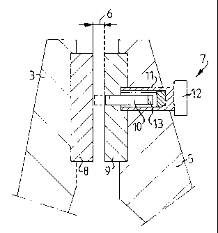
Fig. 2 shows a detail of a sensor mounting in the
stator on a machine according to Fig. 1,
Fig. 3 shows a diagrammatic view of a sensor in
different positions in a stator, and
Fig. 4 shows a diagrammatic view of a machine
displaying inclination between the stator and the
rotor.
Description of exemplary embodiments
Fig. 1 shows diagrammatically those parts of a
machine 1 of the refiner type intended for paper pulp
production which are necessary to understand the
invention. This machine is provided with a rotor 3
which is mounted rotatably in a stand 2, is driven by a
motor 4 and can also be moved axially in the direction
towards and away from a stator 5 in order to regulate
the size of a refining gap 6 between the rotor 3 and
the stator S. For checking the size of the refining gap
6, at least one sensor arrangement 7, with a sensor of
magnetic type which suitably works according to the
reluctance principle, is mounted in the stator S. This
type of sensor is well known to the expert in the
field. Two or more sensor arrangements 7 can suitably
be distributed around the stator S.
As shown in greater detail in Fig. 2, both the
rotor 3 and the stator 5 are provided with refining

CA 02373820 2001-11-09
WO 01/71276 PCT/SEOI/00572
- 4 -
segments 8, 9 which have a surface sui-:~able for
refining paper pulp and are mounted in -;= suitable
number in a ring on the rotor and the sta:or. These
refining segments 8, 9 are subjected to wear during
operation and are therefore suitably replaceably
mounted. In at least one of the refining segments 9,
the stator 5 is provided with a sensor arrangement 7,
in which a sensor 10 is mounted axially displaceably in
a housing 11 which is mounted in a fixed manner in the
stator 5 and can be, for example, screwed into the
stator. The bearing between the sensor 1C and the
housing 11 can be of, for example, the ballscrew type
with small pitch, where a given rotation of an
operating means 12 produces a given axial disnlacement
of the sensor 10 in either direction. The operating
means 12 can consis-: of, for example, a whee=, but it
is also possible to use, for example, an electric
stepping motor or servomotor in order for it to be
possible to effect operation at a distance from the
stator S.
For calibration of the sensor 10, zeroing is
carried out first by the sensor being r.-:oved into
contact with the refining segment 8 on the rotor 3
which, in this connection, is rotating. In order to
make it possible to establish reliabiy when contact is
made between the end of the sensor 10 (s:-,own by a
broken line in Fig. 2) and the refining seg:nent 8 on
the rotor 3, use can be made of, for example, an
accelerometer 13 arranged on the sensor 10. This
accelerometer registers the vibrations whic:- occur on
contact and emits a corresponding signal, w:^.ich makes
it possible to interrupt the feed of the sensor 10 in
time. If appropriate, the accelerometer 13 can be
coupled to a stepping motor forming part of --'ne sensor
arrangement 7, so that the motor interrupts the feed
automatically when a suitable signal is supplied. The
signal obtained from the sensor 10 in this contact
position then represents the zero position of the
sensor. By subsequently reversing the sensor 10 a

CA 02373820 2001-11-09
WO 01/71276 PCT/SEOI/00572
- 5 -
predetermined distance, a new signal is obtained, which
represents the distance covered. In this way, the
sensor is calibrated.
Fig. 3 shows in greater detail the relative
location of the sensor 10 and the refining segment 9 in
different positions of the sensor 10. The position
shown in Fig. 3a, in which the end of the sensor is
level with the surface of the refining segment,
constitutes the normal working position of the sensor.
The position shown in Fig. 3b, in which the sensor
extends outside the refining segment, is used, as
mentioned, for zero calibrating the sensor. The
position shown in Fig. 3c, lastly, in which the sensor
is located slightly inside the surface of the refining
segment, can be used to spare the sensor when contact
between the rotor and the stator has occurred during
operation.
In a machine 1 of the type described here, the
rotor and the stator usually have a rather large
diameter, often of the order of roughly 1.5-2 m, and
the rotor 3 usually rotates at a speed of the order of
roughly 1500-1800 rpm. Even relatively minor bearing
faults can therefore easily result in inclination
between the rotor and the stator of the type shown
diagrammatically in Fig. 4. It is therefore important
that both base mounting and bearing are stable so as to
obtain good parallelism between the rotor and the
stator, so that the gap 6 has the same size overall. By
using a number of suitably positioned sensor
arrangements 7 designed according to the invention,
this can be checked, even during operation. In this
connection, it is suitable to use three such sensor
arrangements 7 which are positioned in a mutually
spaced manner in the circumferential direction of the
stator S. If appropriate, use can be made of only two
diametrically positioned sensor arrangements 7 if
inclination between the rotor and the stator can be
expected to occur in only a certain plane.
The gap 6 usually has a size of roughly 0.30-

CA 02373820 2001-11-09
WO 01/71276 PCT/SE01/00572
- 6 -
1.50 nLcn. 'As the refining segments 8, 9 can be worn down
at such a rate that rotor movement of roughly 2 mm/2000
h is necessary in order to maintain the gap size, it is
obvious that good measuring accuracy is desirable in
order for it to be possible to make suitable
corrections during operation for the purpose of
maintaining a certain product quality.

Representative Drawing
A single figure which represents the drawing illustrating the invention.
Administrative Status

2024-08-01:As part of the Next Generation Patents (NGP) transition, the Canadian Patents Database (CPD) now contains a more detailed Event History, which replicates the Event Log of our new back-office solution.

Please note that "Inactive:" events refers to events no longer in use in our new back-office solution.

For a clearer understanding of the status of the application/patent presented on this page, the site Disclaimer , as well as the definitions for Patent , Event History , Maintenance Fee  and Payment History  should be consulted.

Event History

Description Date
Inactive: Expired (new Act pat) 2021-03-22
Common Representative Appointed 2019-10-30
Grant by Issuance 2009-06-02
Inactive: Cover page published 2009-06-01
Inactive: Final fee received 2009-02-02
Pre-grant 2009-02-02
Notice of Allowance is Issued 2008-09-04
Letter Sent 2008-09-04
Notice of Allowance is Issued 2008-09-04
Inactive: IPC removed 2008-08-30
Inactive: Approved for allowance (AFA) 2008-06-12
Amendment Received - Voluntary Amendment 2008-03-04
Inactive: S.30(2) Rules - Examiner requisition 2007-09-05
Inactive: IPC from MCD 2006-03-12
Letter Sent 2006-02-14
Request for Examination Received 2006-02-02
Request for Examination Requirements Determined Compliant 2006-02-02
All Requirements for Examination Determined Compliant 2006-02-02
Letter Sent 2002-06-07
Inactive: Cover page published 2002-06-03
Inactive: Notice - National entry - No RFE 2002-05-28
Application Received - PCT 2002-03-27
Inactive: Single transfer 2002-01-14
National Entry Requirements Determined Compliant 2001-11-09
Application Published (Open to Public Inspection) 2001-09-27

Abandonment History

There is no abandonment history.

Maintenance Fee

The last payment was received on 2009-03-06

Note : If the full payment has not been received on or before the date indicated, a further fee may be required which may be one of the following

  • the reinstatement fee;
  • the late payment fee; or
  • additional fee to reverse deemed expiry.

Please refer to the CIPO Patent Fees web page to see all current fee amounts.

Owners on Record

Note: Records showing the ownership history in alphabetical order.

Current Owners on Record
DAPROX AB
Past Owners on Record
BENGT AKERBLOM
Past Owners that do not appear in the "Owners on Record" listing will appear in other documentation within the application.
Documents

To view selected files, please enter reCAPTCHA code :


To view images, click a link in the Document Description column. To download the documents, select one or more checkboxes in the first column and then click the "Download Selected in PDF format (Zip Archive)" or the "Download Selected as Single PDF" button.

List of published and non-published patent-specific documents on the CPD .

If you have any difficulty accessing content, you can call the Client Service Centre at 1-866-997-1936 or send them an e-mail at CIPO Client Service Centre.


Document
Description 
Date
(yyyy-mm-dd) 
Number of pages   Size of Image (KB) 
Representative drawing 2001-11-09 1 6
Abstract 2001-11-09 1 52
Drawings 2001-11-09 1 16
Description 2001-11-09 6 226
Claims 2001-11-09 2 81
Cover Page 2002-06-03 1 39
Abstract 2008-03-04 1 20
Description 2008-03-04 7 258
Claims 2008-03-04 2 75
Representative drawing 2009-05-08 1 8
Cover Page 2009-05-08 2 44
Notice of National Entry 2002-05-28 1 194
Courtesy - Certificate of registration (related document(s)) 2002-06-07 1 114
Reminder of maintenance fee due 2002-11-21 1 106
Reminder - Request for Examination 2005-11-22 1 115
Acknowledgement of Request for Examination 2006-02-14 1 177
Commissioner's Notice - Application Found Allowable 2008-09-04 1 163
PCT 2001-11-09 10 285
PCT 2001-11-09 1 65
Fees 2003-02-25 1 38
Fees 2004-02-23 1 37
Fees 2005-02-22 1 36
Fees 2006-02-27 1 34
Fees 2007-03-06 1 35
Fees 2008-03-03 1 35
Correspondence 2009-02-02 1 38
Fees 2009-03-06 1 36