Note: Descriptions are shown in the official language in which they were submitted.
CA 02374469 2001-11-30
AMPHIBIOUS VEHiCLE
The invention relates to an amphibious vehicle with a single drive
motor which can selectively drive a travelling mechanism and a swimming
drive, either independently of one another or both at the same time.
Powered vehicles of many different kinds are finding increased use as
pleasure activities during leisure time. Examples of this are snowmobiles, jet-
skis, or beach choppers which are provided with three or four balloon tires
and thus can move in sand. A disadvantage of the known vehicles is that
they are capable of use only in a single environment, and/or are not suitable
for pleasure purposes. Examples of the latter are belt driven snow vehicles or
amphibious vehicles. The known amphibious vehicles for military or civil use
are relatively large and unshapely. The reason for this is essentially that
the
underside of the powered vehicle has the configuration of a boat hull, in
order
to ensure that it will float. In other embodiments an attempt is made to
improve the drive of conventional powered vehicles by modifications like
outriggers, which cause the attainable water speed to be unsatisfactory.
From DE 35 22 041 Al there is known an all-wheel drive amphibious
vehicle with a high speed in water, in which strong driving forces are created
in water due to the provision of a scoop and baffle system on all four wheels,
which causes the vehicle body to be lifted out of the water. Only the wheels
with the scoops remain in contact with the water. Since this removes the
otherwise high water resistance which otherwise arises due to the shape of
the amphibious vehicle, the forward driving force, likewise created by the
scoop system, lends to the vehicle the necessary high water travelling speed.
The scoops of the system along with their mounting hardware are removeably
secured to the wheels and must be removed prior to travel on land, or
mounted prior to travel over water. As an alternative, it is suggested to
permanently secure the wheels and the scoop system together. A
disadvantage of the known amphibious vehicles, depending upon the
embodiment, is either the labourious mounting or dismounting, or the high
costs for an automatic on-and-off control apparatus for the scoop system.
CA 02374469 2001-11-30
-2-
From DE 38 32 559 C1 there is known an amphibious powered vehicle
with a motor which powers a water drive directly and a land drive by way of a
gear unit, in which a coupling is part of the drive train of the land drive,
the
coupling having a coupling strength, during landing and travel over water,
which is adjustable corresponding to the difference between the actual and
the design r.p.m. of the land drive, such that the drive r.p.m. can be
regulated
up to the design r.p.m. By this means, the drive motor of the amphibious
powered vehicle can be driven onto.land at full r.p.m., so that the water
drive,
which can be in the form of a propeller or a jet, can exert the maximum shove
to support the landing and water travel.
From DE 39 16 200 Al there is known a drive installation for an
amphibious vehicle, in which only a single drive motor is necessary, in spite
of
which the land drive and the water drive can be selectively driven independent
of one another, or simultaneously driven. By this means it is possible, during
simultaneous operation of the land drive and the water drive with only a
single
motor, and preferably at a constant r.p.m. of the motor, for the land travel
drive train and the water travel drive train to be regulated or controlled
independently of one another, as concerns the r.p.m. and the load. This is of
substantial advantage during landing (transfer from water to land) and
launching (transfer from land into water), since, for example, the wheels of
the
amphibious vehicle will not sink into a soft embankment. It is sufficient to
supply a single land drive train for the land drive, and a single water drive
train
for the water drive. If the amphibious vehicle has several water drive
elements, for example several propellers or several hydro-jets, then it is of
advantage for each of these water drive elements to have its own water drive
train, which may be selectively controllable together or independently of one
another.
Accordingly, the invention is directed to the technical problem of
providing a land-travelling amphibious vehicle, particularly for leisure time
CA 02374469 2006-10-19
-3-
activity which, with minimal effort can be switched between land travel and
water travel, and which allows, in both configurations, a satisfactorily high
speed and an open seating arrangement for the drivers of the powered
vehicle.
In accordance with an aspect of the present invention, there is provided an
amphibious vehicle having an open seating arrangement, comprising: an all-
wheel-drive travel drive; a swim drive including a jet drive; at least two
independent clutches; and one driving engine configured to one of reciprocally
and simultaneously power the travel drive and the swim drive via the clutches,
the engine disposed substantially in a center between axles of the travel
drive
below the seating arrangement.
In accordance with another aspect of the present invention, there is provided
an amphibious vehicle having an open seating arrangement, comprising: an
all-wheel-drive travel drive; a swim drive including a jet drive; at least two
independent clutches; and one driving engine configured to one of reciprocally
and simultaneously power the travel drive and the swim drive via the clutches,
the engine disposed substantially in a center between axles of the travel
drive
below the seating arrangement, wherein the travel drive includes front wheels
and rear wheels, tires of the front wheels and the rear wheels including
balloon tires, and wherein the balloon tires of the rear wheels have a larger
volume than the balloon tires of the front wheels.
In accordance with a further aspect of the present invention, there is
provided
an amphibious vehicle having an open seating arrangement, comprising: an
all-wheel-drive travel drive; a swim drive including a jet drive; at least two
independent clutches; and one driving engine configured to one of reciprocally
and simultaneously power the travel drive and the swim drive via the clutches,
the engine disposed substantially in a center between axles of the travel
drive
CA 02374469 2006-10-19
-3a-
below the seating arrangement, further comprising buoyancy bodies arranged
at least one of in a front region and a rear region, wherein the buoyancy
bodies arranged in the front region provide a greater buoyancy than the
buoyancy bodies arranged in the rear region.
In accordance with another aspect of the present invention, there is provided
an method for operating an amphibious vehicle having an open seating
arrangement, the amphibious vehicle including an all-wheel-drive travel drive,
a swim drive including a jet drive, at least two independent clutches, and one
driving engine configured to one of reciprocally and simultaneously power the
travel drive and the swim drive via the clutches, the engine disposed
substantially in a center between axles of the travel drive below the seating
arrangement, the comprising the steps of: engaging the travel drive during a
swim operation; and driving at least one of front wheels and rear wheels of
the
travel drive contrary to a direction of travel.
In accordance with a further aspect of the present invention, there is
provided
an method for operating an amphibious vehicle having an open seating
arrangement, the amphibious vehicle including an all-wheel-drive travel drive,
a swim drive including a jet drive, at least two independent clutches, and one
driving engine configured to one of reciprocally and simultaneously power the
travel drive and the swim drive via the clutches, the engine disposed
substantially in a center between axles of the travel drive below the seating
arrangement, the comprising the steps of: controlling the amphibious vehicle
by swivelling a jet nozzle of the jet drive during a swim operation; and
supporting the controlling step by steering front wheels of travel drive.
Because of the intermediate position of the drive motor, the centre of
gravity of the amphibious vehicle can be displaced in the direction of the
centre of buoyancy such that the centre of gravity of the vehicle is located
in a
CA 02374469 2006-10-19
-3b-
known position above the centre of buoyancy, such that, essentially, no
turning moments arise. By means of this, the amphibious vehicle has a stable
position in the water, despite the open seating arrangement, making possible
a useful water drive. Due to all wheel drive, the amphibious vehicle is fully
capable for travelling on the land, and the water drive, constructed as a jet-
drive, guarantees on the one hand adequate water speeds, while on the
other, in contrast to a propeller, it is not easily damaged during movement,
and, in contrast to a propeller, it is not easily damaged during movement, and
represent no risk to injury to third persons.
In a further preferred embodiment, the wheels of the amphibious
vehicle are constructed as balloon tires, which on the one hand improve the
drive and sand, and on the other hand, when operation on water, act as
buoyant bodies, wherein, for land travel, the rear balloon tires are
preferably
somewhat larger than the front balloon tires.
To improve the buoyancy, it is possible to add, at the front and/or rear
of the amphibious vehicle, additional discrete buoyant bodies, which
preferably are constructed as air tanks. With these discrete buoyant bodies,
which can be designed so as to be disassembled, the buoyancy point can be
better adjusted.
CA 02374469 2001-11-30
-4-
The invention will now be described in greater detail with reference to a
preferred embodiment. In the figures there is shown:
In Figure 1 a schematic side elevation of an amphibious vehicle and
In Figure 2 a schematic bottom plan view of the amphibious vehicle.
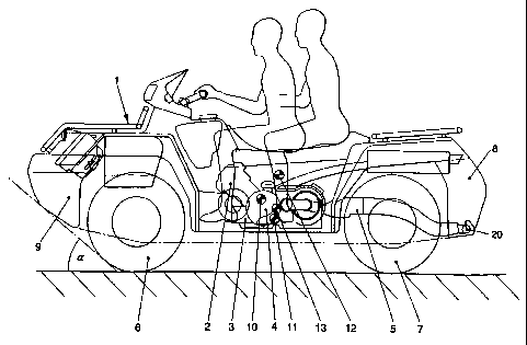
In Figure 1 there is illustrated an amphibious vehicle 1 with an open
seating arrangement for two persons. The amphibious vehicle 1 includes a
drive motor 2, a motor gear unit 3, a first clutch 4 for driving a jet-drive
5, and
two further clutches for the independent operation of the forward wheels 6 and
the rear wheels 7. Further, the amphibious vehicle 1 includes an air tank 8
located in the rearward region of the amphibious vehicle 1, and an air tank 9
positioned in the forward region. The drive motor 2 is located centrally
between the forward axis and the rearward axis, below the driver. By this
means, the centre of gravity 10 is shifted forwardly of the seated position of
the driver when the vehicle is empty. The buoyancy, which is determined
essentially by the balloon tire construction of the forward wheels 6 and the
rearward wheels 7, as well as the two air tanks 8,9, can be adjusted by way of
their dimensioning such that the centre of buoyancy 11 for the vehicle when
empty is located under the seating position of the driver. By way of the
additional weight of the two vehicle passengers, who sit relatively high, the
centre of gravity 12 is displaced by the vehicle gross weight, on the one hand
in the upward direction, and on the other hand below the sitting position of
the
driver. Since the centre of buoyancy 13, due to the vehicle gross weight,
shifts only upwardly, the centre of gravity 12 and the centre of buoyancy 13
are in alignment so that no resulting tuming moment exists, and the
amphibious vehicle 1 assumes a stable floating position. To improve the
streamlining, the air tank 9 is constructed with an oblique portion defining
with
the water surface an angle a of preferably 40 .
CA 02374469 2001-11-30
-5-
A further possibility for improving the centre of buoyancy lies in the
possibility of enlarging the axle width of the amphibious vehicle 1 by
comparison with conventional off-road vehicles, for example the sand-
choppers.
The construction and the operation of the drive train will be explained
below utilizing the schematic bottom plan view shown in Figure 2. The drive
trains include the centrally located drive motor 2 and the motor gear unit 3,
which are arranged with respect to both the land drive and the jet drive 5.
The
motor gear unit 3 is connected with a forward axle gear 15, through a Cardan
drive shaft 14, through which the forward wheels 6 are driven. Moreover, the
motor gear unit 3 is connected through a drive shaft 16 with a rear axle drive
17, through which, by means of a stiff rear axle 18, the two rear wheels 7 are
driveable. In order to disconnect the drive train there are provided at least
two
clutches which are positioned either on the motor gear unit 3 and/or in the
forward axle gear 15 or the rear axle gear 16. The two clutches are
independently controllable. Through coupling 4 the motor gear can be
brought into engagement with a conical gear 19 of the jet-drive 5, whereby the
coupling 4 is independently controllable.
When travelling on land, the coupling 4 is open, and the forward
wheels 6 and/or rear wheels 7 are driven by the drive motor 2 and the motor
gear unit 3. In water operation, the coupling 4 is closed and a propeller is
caused to rotate by engagement with the conical gear 19, the propeller
drawing water in through a bottom opening and forcing it in the direction of
the
jet nozzle 20. The ejected water stream then produces a forward impulse
against the amphibious vehicle 1, on the basis of which the amphibious
vehicle 1 is driven. The drive train can be uncoupled during water drive, or
used as a support for buoyancy. In this connection the rearward motion gear
is selected, so that the forward wheels 6 and the rearward wheels 7 rotate in
the opposite direction of the travelling direction. Utilizing the clutches
which
are independent of each other, the rear wheels 7 can, for example, be driven
CA 02374469 2001-11-30
-6-
alone. Steering during water drive involves primarily the swivelling jet
nozzle
20, wherein engagement of the forward wheels 6 can be called upon for
additional support. Upon landing, the land drive train is connected for
forward
movement, and the drive moment is controlled or regulated such that the
wheels do not dig into the underground. In this connection, for example, one
can use a mechanism in accordance with DE 39 16 200 Al.
CA 02374469 2001-11-30
-7-
LIST OF PARTS
1. Amphibious vehicle
2. Drive motor
3. Motor gear unit
4. Clutch
5. Jet-drive
6. Forward wheels
7. Rear wheels
8. Air tank
9. Air tank
10. Centre of gravity when the vehicle is empty
11. Centre of buoyancy when the vehicle is empty
12. Centre of gravity under vehicle gross weight
13. Centre of buoyancy under vehicle gross weight
14. Cardan axle
15. Forward axis gear
16. Drive shaft
17. Rearward axle gear
18. Rearward axle
19. Conical wheel drive
20. Jet nozzle