Note: Descriptions are shown in the official language in which they were submitted.
CA 02374746 2002-03-13
- 1_
-- This is a divisional application of co-pending application
2,165,166, filed April 13, 1995.
BLOOD PL'1'~P DE'~T_CE :~~1D '~ETuOD OF PRODUCT_NG
FT:Z,D OF TuE INVF.N't'TON
~=.C_.C~.. _ dC...._..... .. .~.~ :t~~..~. _.. ~ °-.,.._ .."
medical devices. More spec~.~.ca_ly, tae presan~ _nven~.ion is
related yo a blood dump device for cardiac assist.
BACKGROUND OF '~i':E I?3V=NTION
cSS=S ~. .i°_V _C~S a~'3 "eC2 :.'lw:~C
Ve::i.~iC'al ar
eve= ;. rea y. ..: ~ scic=a c_! Htner = l 00 , 000
:1C~ S lng a ~'..e:lt Cr m:.._
elite"' Cans ar °_ Qia~noS2~ W=~:'? ccngesslVe ":ear',. ~3=1 ur
° e~C n
a P .:'~ Gal V=" . ~. . idul ~ and Je:_a ~= _C
0 yea= (R::~ r., . , _.,
~. "' C'.:l~r ~ "'- ~ ~a-~l'ar' ..~. ~L:al ~ . _. . ( ?C ) , Car~.'~aC
Ve_ ~_ _ e...- ... -, = r
Mechanical Assistance 3eyond 3allooa Punning, St. Louis,
Mcsby ,ng~ pc. ..-2~) . As ~ =esu=_, c:;llaborat_ve ef'or=s
., ,
amonc heals: car. professionals have focussed on tae
i5 development cf varicus sys~e:.~.s to assist t'_'_~.e =a_ling heart.
~~hese _comprise both extracorpcreal and ~u~Dia.~W.3ble pulsa~ile
ventricular assist devices (V=D), as well as nen-pulsar: 1e
assist pumps.
E~~racorporeal systems include the Pierce-DOnachy
20 VAD and the Abiomed BVS-5000 VAD. The Pierce-Donachy VAD is
positioned on the patient's abdomen and propels blood by
means c~ a ~neumatically actuated diaphra5.n. =~s use as a
bridge to transplant is well-documented (Pee, W.E.,
Rosenberg, G., Donachy, J.H., et al.: Mechanical circulatory
25 assistance for postoperative cardiogenic shock: A three-year
experience. ASAIo Trans 26:256-260, 1980; Pennington, D.G.,
Kanter, K.R. , Mc9ride, L.R. , e~ al. : Seven years' experience
w:.th the Pierce-Donachy ventricular assist device. J Thorac
Cardiovasc Surg 96:901-911, 1988). The Abiomed BVS-5000,
CA 02374746 2002-03-13
also an ex tr acorporeal deV~Ce , .S .. ~Xe,.~. Ver ,'_~Cal ~ .! a' tile
patient's bedside and is attached to the heart with
percutaneous cannulae t'. at ex=t the patient's chest below the
cc -~ ' ,~,---'_:~ Cha~,psa~.:~ '; ~ :~.e- - crier or, , v e
s,.__ ~ : ~, _., __ _, ..., , , .,
al.: Use of the Abiomed 3VS System 5000 as a bridge to
cardiac transplantation. J Thorac Cardiovasc Surg
100:122-128, 1990).
- am
The mos t .r °cue.~, tlv used '_:~cian;.a'.~,le svs ~ s f cr
W 1 ~ 7 ~ 'a ' ~ = l p t \ nr
c__n_ca_ ~pr_ =c..t__..r. nc_ud_ _ a ~c-; acor V.~D _Icvac,.
Divi sicn, Baxter Health Care Gorp. ) ar, the ear tmate
(Ther~ocardiosvst_ms) (Rows=s, J .R. , _M_cr timer , 3.J . , 015en,
D. B. : Vertricul ar Assist and T;.zal Art_=icial near t Cevices
for Cl i:.ical LTS2 l n 199., . ASaIG J ~9: 3~0-0~ , .°9~ ) . The
Novacor uses a solencid-dr_ven s;.rinc to actuate a dual
pus:Zer nla~e. The p,us:-:er b_a~... co. _
'ilTJreSS25 a
polyurethane-lined chamber which cruses ejection :,f blooc
(Pcrtner, P.M. , Jassawal la, J .S. , Cher., :l. , et a? ~ A new
dual pusher-plate left hear assist blood pump. Artif organs
(Supply 3:361-365, 1979). ,:,ikewise, the Heartmate consists
of a polyurethane lined chamber surrounded by a pusher plate
assembly, but a pneumatic system is used to actuate the
pusher plate (Dasse, K.A., Chipman, S.D., Sherman, C.N., et
al.: Clinical experience with textured blood contacting
surfaces in ventricular assist devices. ASAIO Trans
33:418-425, 1987).
Ef f icacy of both the extr acorporeal and imp 1 antable
pulsatile systems has been shown (Rowles, J.R., Mortimer,
B.J., Olsen, D.B.: Ventricular Assist and Total Ar~~ficial
Heart Devices for Clinical Use in 1993. ASAIO J 39:840-855,
1993). However, certain complications are associated with
the use of extracorporeal systems, including relatively
CA 02374746 2002-03-13
.Z_
lengthy surgical imp l anta tion procedur es and 1 imi red as tie.~. t
mobility. The use of totally implantable systems raises
COnC .°C~_~.S SslC:: aS f::. ~ . COSL Ci .'.~':e deVlCe , C.~rlLly.~. '
off: de~ri CB
::,esi~~ and aca_~ ____ive~~ __c=__~_~ _..___ _..... ___._.. ~~es.
,~-, _ ~, = _ _
Cent~yfugal pump VADs oz~er several advantages over
their pulsatile cnunterpar,ts. They are much less costly;
they rely on less comalicated operating principles; and, i.~.
general, they requ~.~-= 1 ess _nvolt,~ed surgica- _.-.:~cl artatic
procec~.:Yes sine , _.. some app 1 :. ~a t=cns . ,.ara:cpu! :1G~ ~~ ":'
.0 bypass (CP3) is nct rscui=ed. Thus, an. -:pia.~.tabl °_
centrifugal pump may be a better a1 terrat;ve '~o c~~rrentlv
aVall able AX~=aCOypCi eal TADS . Cr' S.:Cr ~- C.'. :"ediL;:-L2r.;v
aSSlSt (~-~ mCntn S) . _n ,a.CC:~=Cn, ~°_ ~,:52 ..~ Ccnt_._':lga.
pumps in medi u:.~.-te=-m applicati;,ns l,1-5 :~cr.th s; :aav allow the
3lCre CCmpl °X, °XpenS_'le v'ADs, nanlel~J ..= °_
:ZG~~IaC.~.~ 3::d '._:1e
Heartaate, to be used in longer term appl_caticns where
higher cost, increased device compiexitv, and involved
surgical procedures may be justified.
Prior art relating to cents ifugal blood pumps is
Canadian Patent No. 1078255 to Reich; U.S. Patent No.
4,921,407 to Dorman; U.S. Patent No. 3,608,u88 to Dorman;
U.S. Patent No. 4,135,253 to Reich; Development of the
Baylor-Nikkiso centrifugal pump with a purging system for
circulatory support, Naifo, :~C. , Miyazoe, Y. , A~ zawa, T. ,
Mizuguchi, K., Tasai, K., Ohara, Y., Orime, Y., Glueck, J.,
Takatani, S. , Noon, G. P. , and Nose ~ , Y. , Artif . Organs, 1993 ;
17:614-618; A compact centrifugal pump for cardiopulmonary
bypass, Sasaki, T., Jikuya, T., Aizawa, T., Shiono, M.,
Sakuma, I., Takatani, S., Glueck, J., Noon, G.P., Nose', Y.,
and Debakey, M.E., Artif. Organs 1992;16:592-598; Development
of a Compact Centrifugal Pump with Purging System for
CA 02374746 2002-03-13
-4-
Circulatory Support; Four Month Survival with an Implanted
Centrifugal Ventricular Assist Device, A.H. Goldstein, MD;
WO 91/01584, published February 7, 1991, titled "Radial Drive for
Implantable Centrifugal Cardiac Assist Pump" University of
Minnesota; Baylor Multipurpose Circulatory Support System for
Short-to-Long Term Use, Shiono et al., ASAIO Journal 1992, M301.
Currently, centrifugal pumps are not implantable and are
used clinically only for CPB . Examples include the Biomedisum and
the Sarns centrifugal pumps. The Biomedicus pump consists of an
impeller comprised of stacked parallel cones. A constrained
vortex is created upon rotation of the impeller with an output
blood flow proportional to pump rotational speed (Lynch, M.F.,
Paterson, D., Baxter, V.: Centrifugal blood pumping for open-
heart surgery. Minn Med 61:536, 1978). The Sarns pump consists of
a waned impeller. Rotation of the impeller causes flow to be
drawn. through the inlet port of the pump and discharged via the
pump outlet port (Joyce, L.D., Kiser, J.C., Eales, F., et al.:
Experience with the Sarns centrifugal pump as a ventricular
assist device. ASAIO Trans 36:M619-M623, 1990). Because of the
interface betweer_ the spinning impeller shaft and the blood seal,
several problems exist with both these pumps, including excessive
wear at this interface, thrombus formation, and blood seepage
into the motor causing eventual pump failure (Sharp, M.K.: An
orbiting scroll blood pump without valves or rotating seals.
ASAIO J 40:41-48, 1994; Ohara, Y., Makihiko, K., Orime, Y., et
al.: An ultimate, compact, seal-less centrifugal ventricular
assist device: baylor C-Gyro pump. Artif Organs 18:17-24, 1994).
CA 02374746 2002-03-13
The AB-180 a anoth er type cf centrifugal bleed
pump that is designed to assist blood circulation in patients
who suffer hear t failu=_. As i1 1 usL=at=_d in fi re
gu_ '_ , ~h a
.~rZr.~v ...via_C ~S .~... C?~~ ~.. _ _ a'__~ .~.v. DC er...._ . .?,. =~~'l~~
;, a stator 2, a rcLcr 3, a ;~curna'_ ~, a seal 5, an impeller
6, and an upper housing ?. The ccmpcnenLS are manufactured
by various vendors. The fabrication is performed at
All egheny-Singer Research Ins ti.ute in Pittsburgh,
Pennsv l va; : is .
l0 The r ctor ~ _s =n t::e lcwer ::ouslnc ~ and _a oos;:
protrudes through a '.he 1 a in t a jcurnal -".". . The ~~pe ~ ~ er o
pumps blood in t!~e upper hcus_.~.~ ~ and =__ ~::=eased _:~LO and
r;r L3Le5 w.th the . .7tOr ~ . '-'~i2 ~ _~ '
_:.tue.:._ Si.Gi' passes '..r pug:
a rubber Seal ~ dl spCSZd :.eLNe°_~~ t:le uppe_ hCLSlng ! and
t°_
1~ jCUr:.al 4, rOtrJr and StaL:r aSS2r1b1V. ?'~'?e '1DL'er hOLS_nC % 'S
t:lreaded lnLO the lower hOL:S=ng 1 and ? t CC:.lpr°SSeS the OLlLe=
edge of a rubber Seal ~ ~o Cr as to a blcOd contac ring Chamber .
In this manner, blood does not contact the rotor 3, journal
4, or lower housing 1. The upper housing 7 is connected to
20 an inlet and outlet flew tubes 8, 9, called cannulae, that
are connected to' the patient' s circulatory sys tom, suc:~ as
between the left atrium, La, and the descending thoracic
aorta, DTA, respectively. Through this ccnnection, blocs can
be drawn fr om the lef t atr ium, LA, through the pump, and out
25 tc the aorta, DTA.
The impeller 6 w ins by means of the rotor 3 and
stator 2 which make up a DC brushl ess motor . The base of the
rotor 3 has four magnets that make up t-~ro north-south pole
pairs which are positioned 90 degrees apart. The stator 2 is
30 positioned around the rotor 3 on the lower housing 1. The
stator 2 comprises three phases. When it is energized, it
CA 02374746 2002-03-13
- rj _
cr sates a magnetic f crce that counter ac is t a .;,agnets in the
rotor 3 causing the rotor 3 and impeller 6 to spin, as is
y
wet known wi ~h Lrushl ess DC .;.pros.
A peristal tic pump infuses lubricating fluid into
a port of the lower housing to lubricate the spinning rotor.
The fluid prevents contact, bet;aeen any solid internal pump
components during pump activation.. It for-is a layer cf
approximately 0.001 inches around the rotor and the impeller
sha.. T':is fluid bearing esse.~.o_a? .v a ' ws .. r
.. .:.~~ ~a -Tr ~e
opera ticn of 'the pump . '''he f l ~~id passes ar cunc 'the . ctor anc
flows up along the rotor post. Eventually, _.. passes cut
throuGh the rubber seal S and i nto =.::e upper ncusing ' at ~ a
i l ~ or = t/ a ' ~ ar - o ~ 1 ' ~: C a v '~:'- .
mpe____ shad. s2__ nr.__=ac... u_.. does r. z sc oe _ _::uc:.
the cuter perlpher=.l of the housing seal beca~.ae the upper
5 hcus_ng is t'_ght'ned down anc sealed :ait:~ ? =vbber G-. i.~.g t..
prevent leakage.
The spinning impeller 6 within the top housing 7
causes f 1 uid to be drawn from the inlet f 1 ow tube 3 towar
the eye of the impeller. The impeller 6 t:~en thrusis the
fluid out to the periphery of the upper housing 7. At this
point, tt-~e fluid i5 pushed through the outlet tube 9 by
centrifugal force. The pump typically consumes 3-5 Watts of
input power to per f orm the hydraulic work necessary to attain
significant physiologic benefits.
The prior art AB-180 pump has certain drawbacks
which limit its efficacy as a cardiac assist device. The
present invention describes several discoveries and novel
constructions and methods which vastly improve such a pump's
operation.
CA 02374746 2002-03-13
SL'~L~R'! V E TZ:E TNVENTION
T he or esen t _-:~.en ;.:~cn per rains =c _ blood ou:~~a
de~:~;ce. '~.:e ~,_..,... ... ~=-: _.._ _... '_ses a ___..~ ou-r ..a-:_:.c
_ _ _ _ ."_
blood tr anspor t por is and cann u1 ae connec to ca the pcr ~s .
The blood pump device also comprises a coo='_ng material
covering the junction Set-.peen the inner surfaces of the pores
and cannulae. This =cr:~s a smooth transit_on so blood can
f low unimpeded t~ er .f= cm and ccl l ec ticn ca«'_ =ies ':;r
blOCd 3r°_ e~ 1L"~~.~.c~2 : :._':°_ ~.~.;re:ltlCn ~S ,'..:.SO
=e~ cue.', °_~ ,.. .3
~ 0 method Of .JrOCIUC~nC a S:,1CC:.h CCatlnCl.
The ~re52n:. l:lVe:l~=On 1S a ..iOCd ~Li:Vp deViCe
campy: sing a second pCrt=cn having a Stator :~eczan~s:a and a
r otor mechanise d_SpCSer'. adacent to and dr'_ver. ~y the s rotor
iilP.C~'lanlsi~l. The S2cCnd :JCr ~_on has a jCLlr:ia_ d_SpOSe~ abCLI~
the r otor mechanism to provide suppor t therewi t. The second
portion has an impeller diswosed in the camber and a
one-niece seal member for sealing about a shaft of the
impeller. The seal member is ffixedly attac:~ed to the journal
so that the seal me:zber is supported by t:~e journal.
Preferably, the rotor has a rotor post connected to
the impeller shaft and an end adjacent to the seal member.
The end has rounded edges to pr event abut.-nent against any
adhesive mater ial disposed bet~reen the sea' member and the
journal.
The present invention is also a blood pump device
which has an infusien port for providing lubricant material
about the rotor, the infusion port has an inner diameter
greater than .05 inches for minimizing pressure needed to
introduce lubricant material into the blood pump.
CA 02374746 2002-03-13
-a-
The present inve.~.zion is also =elated to means for
providing power to the blood pump so that blood can be pumped
thr cugh a cannul ae . Th a pr oviding -~ear.s .~c l udes a
_ = ha v_rc m
~..r.,._c_? a eans _.._ se..~.s'_~g pu.-.:~ _a='_ur=_ and a~
output terminal for actuating a sa=ety occ'_uder l:: an event
of pump failure. Preferably, there is a safety occludes
device disposed about the cannulae and in communication with
the output ter:ainal. Preferably, ~he blood pump c~:npris2s a
motor having s tutor r,.achanis:a and a rotor :aechanis:a. :riven bw
the s~azor mechanism. The sensing means o..:~prises :jeans =cr
det'rmiring back elec~remagnet_c Lorce ;Y_t'. in ~:.e s~afor
r~ l r rar y~c -~ l 1 l ~ r~Y
me..han_sm. P_e____ably, ~_._ contr,.___ng ::~e_rs has .:,eans
1 1 1 ~ O T 1 pr~ ~~ Gf'~
prcv_d_ng s~gnais _nd~cat.. c_ s~a~cr csrr_..,. and r.,.. sce_..,
respectively. The providi::a means is in conmunica~ion wish
the means fer de tzrnining back elec ~r omac;:e ~_c f or ce in the
s~-~ator mechani s:a.
BRI F DESCRIF'T_'ION OF -'z:', DR.~.w ~ VGS
In the accompanying drawings, the preferred
embodiment of the invention and pre=erred :aeThods of
practicing the invention are illustrated in whic'.~.:
Figure 1 is a schematic representation showing a
centrifugal blood pump device of y~.he prior ar~.
Figure 2 is a schematic representation showing the
blood pump device of the present invention and an associated
system.
Figures 3a and 3b are schematic representations
showing a blood collection cavity at the junction between
CA 02374746 2002-03-13
-Q-
port and cannul ae and coat,.~,g ;aa~._r~.a1 cve= the junct'_cr:
between part and cannulae, respectively.
_lCUr°_S ~a anQ '.:, 3r? Sv.::2:~,.__ _-TY~C~e'1L,...._~::s
showing a prior ar ~ seal cons ~=vc Lion and tile preS2n L
inventions se31 COIls:.ruC~lOn, respe.~.Live~V.
Figures 5a and 5b ara Schematic representaticns
ShOWing a prior ar ~ rct.~r. pos ~ and the r~ ~~~ pos ~ ;,= t:~e
pr 85enL lnVenLlOn, 1.'2S7eC L1'Je~ ~,',
Figures oa and 6b are sch erratic r ~~resen ~a ~=cns
showing a prior ar ~ i.~.fusion pcr~ and th a _..fusion pcr ~ c=
the present invention, respec~~velv.
F igur es 7a and ; b ar s sc:. :~a t_,. _
~°_ "ear°S2.~.La ~~C.~.S
showing a mold for cas ti ng the s tatcr as t:~err a_ly ccnduc ~~.ve
epoxy.
Figure 8 is a schematic rapresenta~_on showing the
housing jig of the cannulae coating apparat~,a.
Figure 9 is a schematic representation showing the
cannulae coating apparatus.
Figure 10a is a photograph showing a massive clot
on the impeller and at shaft/seal interface from the 14-day
study.
Figure lOb is a photograph showing a clot-free pump
seal in the 10-day study.
CA 02374746 2002-03-13
.1 ~ ~.
Figure l Oc is a pho tograph showing a 2m:;. c l ct a
the shat t/seal interface in the 28-day study.
_ ' Cur °_ ~~C :.S a ..~.i:CLCC"STJf: Sv:Cw ~::C ~ C~C r.-_= °E -
1:i _
seal in the 154-day study.
Figures lla and 11 b are photographs showing r~ss t on
the rotor in the 14-day study and no bust present in the 154-
day s t~sdy, r espec tiwe 1 y .
Figures 12a and 12b are phcLOaraphs showina Lhe
prior art stator and the stator of the present inventicn,
to r~saectively.
Figur a 13 a a b 1 ock d=agram oT one e:~bcdi:~ent of
the senserless blood pump controller i.~, accordance w~.th the
present invention showing the exteraa~. connections to the
personal computer BLDC motor (blood punp device;, occludes,
extended battery supply, power supply, and infusion pressure
input.
Figure 14 is a block diagram of one embodiment of
tte sensorless blood pump controller in accordance with the
present invention showing the components that control and
regulate and monitor the operation of the sensorless blood
pump controller.
Figure 15 is a block diagram of one embodiment of
the sensorless blood pump controller in accordance with the
present invention showing the internal power supply, external
power supply, battery back-up, and battery charger circuits.
CA 02374746 2002-03-13
.1 7 .
Figure 16 is a block diagram of one embodiment of
the sensorless blood pump controller in accordance wit. the
a ~ e:' =. ''-::e r
~r sent nv ~t en s:~owinc _ powe d s~==bu~. on.
Figure I7 is a block diagram of one embodiment of
the sensorless blood pump controller in accordance with the
present invention showing she Contr of En~ry Devi ce as used
with the cont_ o? entry micr ocomputer and the cc:: fr c
_w-::::ar.--'r. .
F ~ ro ~ i "1 r ~ y ~r-_y..,
gu_ _ to s a L _owcha_ ~ stow ng ~he s u~
seguence for t:~e motor, the measurement of the pump
par ameter s , ~,isplay of pu~p par ameters , and down lcacing c.
:,uma barame_ers to an I3M personal ccmouzer.
Figures ?9 is a block diagram of one embcd_ment c
the sensorless blood pump controller in accordance wish the
present invention showing the signal conditioner inputs to
the control microcomputer, the output that compensates for a
retrograde flow, the alarm '-.hat is activated for low infusion
pressure, the low battery indicator, the occluder output, the
alphanumeric LCD display, and the connection to an external
IBM computer.
Figure 20 is a flowchart of the error checks
including blood pump malfunction, retrograde flow and low
infusion pressure that results in a corrective action or alarm.
CA 02374746 2002-03-13
.1 2.
DESCRIPTION OF THE PRE'F=R.R~D EMBODI'~ENT
Refers.'..~.~ nCS~% tC t=le dr3w~.:1C5 WIl=_.n
1=.:i
-~=orVn o r~ ~-~-_- S~~_~~~ C~ _~e::v.~C~_
_ _ _ c nu~:e_ _s _ _ _
thr oughout the several v=ews , and more spec if ica 1 1 y tc
f igur a
2 thereof, there is shown a blood pump device
10. The blood
pump 10 comprises a blocd pump 12 having a blood transport
per 14 and a cannulae 15 connected to the part 14. As bes;.
s:~own i:1 figure 3b, the blood pump device 10 alsu comerises
a ccatine :~arerra. 13 ccveri:.g tZe -"ncticn ~.w~:JEn t~e irv~=,.
l0 surf aces of the per ~ . : and cannel ae se tha t a smec
lo' t h
transit=on surface 2o a formed and blocs can flow smcothlv
~.h__ om and co 1 ? ecticn csvi ties for t a b1 cod as a
r
e11~1:lated.
The inlet car..nul ae ? 5 can be inserte~ into the lef
atrium of the patient Z2 and fixed with a double pu_Yse strinc
suture. The outlet cane ulae 15 car. be sewn to the aorta cf
the patient 22. The inner junctions of the cannulae 15, 16
are coated with a polyurethane coating material 18 such as
Biomes, manufactured by Ethicon, Inc. The coating material
18 provides a smooth transition surf ace 2o for the blood to
flow on. This uniform transition is essential for reduction
of clot formation.
The techniaue used to apply this coating material
18 is novel. It involves applying the polyurethane material
18 to the collection cavity 93 at the cannulae/port internal
interface with a needle and syringe. After the polyurethane
18 is deposited, it is distributed evenly by hand rotation of
the housing.
CA 02374746 2002-03-13
-- -13-
Next, as shown in figures 9 and 10, the upper housing 26 is
spun axially for each cannula 15, 16 in a motor driven coating
chamber 92 for 24 hours . This promotes more uniform distribution of
the polyurethane 18 and allows full curing. It also assures that
the polyurethane coating 18 fills the step-off between the housing
ports and the cannulae. The coating chamber 92 consists of a motor
shaft 94 enclosed by a plexiglass box 96. The shaft 94 is connected
to a variable speed motor 95 protruding through the rear of the
box. Nitrogen is passed through a jig 97 which fastens to the motor
95 and holds the pump housing 26 and cannulae 15, 16. The jig 97
directs nitrogen from container 98 to pass over the junction being
coated. The nitrogen carries away the solvent gases form the
polyurethane 18 that would otherwise attack and degrade other areas
of the pump housing 26 . The custom j ig 97 functions to hold the top
housing 26 in both configurations, one for coating the inlet flow
cannulae 15 and the other for coating the outlet flow cannulae 17.
Once the polyurethane 18 is cured and evenly distributed, the
housing.26 is removed and the process is repeated for the other
cannula.
As shown in figure 3a, a prior art pump without the coating
technique fortes a collection cavity 93. The prior art blood pump
was implanted in 14 sheep in an experiment from December 1988 to
October 1990. (Modified Fabrication Techniques Lead to Improved
Centrifugal Blood Pump Performance, John J. Patella et al.,
presented at the 40th Anniversary Meeting of~ the American Society
for Artificial Internal Organs, San Francisco, California, April
1994). The pump was arranged extracorporeally in a left atrial to
descending aortic cannulation scheme and the animals survived up to
13 days
CA 02374746 2002-03-13
.t ~-
with the i~aplan~ed prier arm device. These experiments
revealed that a major problem cf the prior arm pump was
t:rcmbus for:"a~_cn Nit:_n c::e ..cllection cav~w __ _.. to
~......__.:e % =cus__ :..ca==_cas.
In contr as, using the described anti t'.~_r cmbogenic
coa ring technict:e wi th coating mater is l . 18 , 4='. s:.eep were
implanted with the blood pump devise f=om ?a~~-?°93 f cr
~.°_r~OdS Of ~ d~cV L~ . 4 d3= S c:1.'. ::G -~'lr aTl~::115 ~aaS CL.~.d
c i_ t'_:°_
_..~°riaC°. ?'rl~S .°D~°_Se.~.~:i ''a, .'.~~;a
=:~C:(.~cS r~~.r. '.~ ~,~.~d~3.
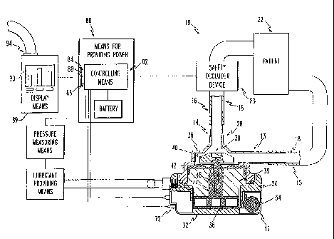
ASS s:zown in _=cur =_ 2 , t a biacd pur.,p device . J
ccmpr ises a f ~.r s t per ~=cn 2 9 having a c:~amber 3 0
and an _nle-
and curl et por= 13 , 1 '_ ;:: f laid=c ccmnun_caticr w_
c:~ t::e
c :amber 30 . The b1 ced pump device 1 0 also comprises a
second
per ion 32 having a sta ~or -sec: ans., 34 and a r o for
.~:ec:~anis.;,
3 6 dis5osed ad j actin ~ to and dr ;Ven by the s ~accr :,iec
han i sm
3 4 . Together , the s ~a for meth anism :; 4 and tze r otcr
mechanism 3 6 f or:a the mo for 3 8 8 . Pr ef er ably , the
wotor 8 8 3
is a brushless DC motor (BLDC) 883. The second portion 32
has a j ournal 3 8 disposed abou t the rotor mechanism 3
6 to
provide support therewith. The second portion 32 also has
an
impeller 40 disposed in the chamber 30 and a one-piece seal
F
member 42 for sealing about a shaf t of the impeller 40 .
The
seal member 42 is fixedly a ~tached to the j ournal 3 8 ,
such as
with adhesive, so that t.'~e seal member ~42 is supported
by the
journal 38. Preferably, the seal member 42 comprises a
coating surrounding and sealing its outer surf ace. Further
,
the rotor 36 preferably has a surface 44 which has been
polished to a surface finish of less than 2.54um for enhanced
low friction operation. The amount of material removed from
the rotor 36 during the polishing process is less than 0.0001
inches (2.54 um).
CA 02374746 2002-03-13
As szown in figures 4a an 4:., v he hare plastic
journal 38 and seal member 42 is fastened together, such as
W'_th T~OC.'__te "-.'J~ ad~?eS:.Ve ~;. aC.~.1°VS SeS~
_...._'_.'l°_c, ri!:_C.~.
wGS .V~C'.:S__i C :r r ~,.,,r.. .:~J _ :e .s.eL ;_ . _ .. .... ..,r._ ' .v._
_ ..SC~ . . _ __
the prior seal 43. Also, the seal member -~2 car. be coated
with Biomer (Ethicon, T_nc. ) polyuretha.~.e for e.~.~.anced
anti thr ombogenici ty .
Two y.:.pr ovements in purer c:~ar ac ~==:s ~vcs gave be=.~.
mace t::rouc;:. this new seal 42. :i=sue, ~~e ~~_~ ~~~ cr,~.,.,.....ic:;
of the seal member ~-.2 :.as been de~reasec sio::_=icantiv. The
prior seal 43 had a metal inser L 4~ ~::at :,gas rec'~_=ed Lo
malnL3=:1 S2a1 SL==~:IeSS, S_.:7C° :.ne S23~'_ =~ __ ::lace C= SCf ~,
i1 r~x~'~,,~~ 1e rubber . The diSCl CS2d COnS Lr::CL_.... O~ Lh °_
"'''°S2:1L
lnVentiOn ei'_:l~naLeS the nee_~, for an ..nS2r= and S~T.~.__f.eS
the molding process. ~_'he seal member 42 is c''.:ed ci==c~lv ~:.
the j ournal 3 8 , which is made of rar d p~.as ~i c, to achieve
overall seal st'_'fness. ~_'he process of ._uing these two
components is si:..ple and rel ies on an inex~e.~.sive ad'.~.esi ve.
Second, this insert 45 had to be machined seoaratelv placed
in the rubber seal 43. As a result, the fabrication Drocess
of the seal left metallic sections of the insert 45 exbosed
to fluid contamination and therefore prone to rust. Since
the seal member 42 of the present invention eliminates the
insert, no steel is present for potential _=on oxidation.
Further, the overal l height, E, of the journal /seal
assembly has been increased from approximately .928 inches to
.944 inches. This has resulted in a tigh:.er seal at the
junction between the outer rim 49 of the seal member 42 and
the top housing 26, decreasing the chance for blood stasis
and clot formation. As the top housing 26 is tightened down
upon the lower housing 24 through their threaded connection,
CA 02374746 2002-03-13
r
5-
it compresses the outer ri:a .~~ oL t'.~.e seal ~2. Th a i:,creased
journal/se:.l height allows this compression to occur closer
two r-'i r~~t~ n ' -~~ - roay ~'.~ ' .-is - =p v r
to _. he : __.:._..g o~ ___ ____ s . _ c she :,=off __ , ~ sppe_
hcusi:.~ ~::e_= _.,. _ ~:eec ~:. ~~ _ .. .... ~e~ as _.._ ..._ ~uc : ~ he
:, threads to achieve the say a tightness as _,. wou ~ d i = the
journal/seal height, E, was not increased. 3ecause of this,
theta is more room to achieve a tig:Zter seal.
T A " ' i ~ = n ~~~~ -,roforr °i".. T'~ "he
h.. ~::_ . w_ c ,. ,.~ d~.me..s_cns of _ se.._
constr~sctions s:.cw~ .:: ..:.ur=s 4a and 4::
CA 02374746 2002-03-13
~i-
A = .2~3 in.
B = .208 in.
C = . 06 1.r..
__ _ ._..
S E = .944 in.
The journal /seal design, as shown ~~n figure 4b, has
been used in the disclosed sheep i mplanta:.icn studies and has
funCticned SuDeT_'~'Jly. ~eSS:~'..~~ .~i ~:le S'..'.:Gj.eS naV2 SIIOWn
lllC~nseauent;al quanz_ ~.;.ES ~?' =:~r =i',::u=: r3 Z" :l.ni~ =''e
D°_r' ~Ile~'7
cf the top housing 2 5 i_~. a f ew cases and ncr.e .:. cZe ~aj or_ =w
of the studies.
As bes t shown _n ~gur a 5b, the ~~~ a ce ~ 0 ef ~= a
rotcr pos t 4 6 is prat er ab 1 y = ounde~ to a ~ _ow a be ~ per
under the seal me:~ber 4 2 . '"':e r:, to oos t 4 0 _s .: ser ~sd .::".
the j ourna l 3 8 and f i is j us t benea to the seal :,tember 4 2 . T':e
junction between the jcurnal 33 and the sea. :ember 46 cccurs
at this poin t and the two components ar a a~ f fixed wi ~h
adhes five ( i . a . Locti to 4 O 1 ) . The r ounding of tze edge 5 0 cn
the rotor post 46 prevents the rotor 36 from rubbing against
any excess glue that may be present after the seal member 42
and journal 38 are fastened together.
The surfaces of the rotor 36 are preferably
polished to 2.54 ~m and given a rust-proof coating 5a.
Results from the sheep studies have revealed little evidence
of rust and polished surfaces have been shown to greatly
increase durability between the rotor 36 and journal 38 and
between the rotor 56 and the lower housing 60.
As best shown in figures 6a and 6b, the infusion
port 62 is preferably enlarged from 0.03 inches to 0.062
CA 02374746 2002-03-13
inches. The housing 24 and pcr~ 62 can also be cryocenvcsl.y
debur~ed. Further, a 1/4 28 UNF male luer lock 66 is used
ins~sad of the price ~;'.: ZS UNF ~hraaded hey barb 53 ~o
~~~..v...T:a'-~ ~ ..'~.. .:.a-e-_~.....~_ ~ ...,...._~it O~= Gs
The port 62 serves as a passageway for pump .
lubricant, suc:~~ as water or saline, which is del ivered to the
.'.' pump and exits through the rubber seal me:~ber 42 =nto the
blood stream. "'he ooh~ 02 a er.'_araed because i t ass_st_~ :..
at tair~inc lower pun-. ' wb= ~.,~=nr_ pr essur es , wh'_c:: d_.;a::is ne::
tle S'~eSS On all lu;,..,'iC3:lv. SV5v.3?T.1 CCmpOnenS. c~~s~v, a ST~la_~.
pot ~ :.S mOr°_ ilke l y to beco-~e occluded wi ~:~ debt is ; a . g .
sa'_
depos'_t =tom lubricant sa_ine solution) and cause =:creases
in lubricant pr=ssures.
The male-femal= junco=on 54 in ~::e prey=cus des_c:.
(figure 6a) was e1 iminat~d to decreases the chance ;.= foreign
debri s in the ches ~. cavi ~y from inf i1 =r 3tinC ' nto Lle
lubricant system. The use of a threaded barb 6o helps to
solve this problem because there is one less junction. The
threaded end is screwed into the lower housing 60 and
chemically sealed and the barbed end is inserted directly
into the lubricant tubing 69 creating a mechanical seal.
The deburring of the housing 60 results in
increased durability and improved pump performance and lower
internal lubricant temperatures. The internal lubricant
temperature was measured by inserting an Omega, Inc 33 Gauge
hypodermic needle thermocouple directly through the pump
baffle seal, just below the lip of the seal where the
lubricant passes out. We found that rough (undeburred)
component surf aces of the prior pump resulted in internal
lubricant temperatures of 50°C. The lubricant temperatures
CA 02374746 2002-03-13
C. a ~.~V:L"._.~. GeV~Ce .~"~' ii~~:l ~"_~Si:2.~~., debLl~~°G
C:.'.:v..~..:ie:l~~ 'vdaS
f ound to be 42-4 3 ° C, which is sigr.if icant'_y less . Since hea t
is c::cug::~ _.. ~e a possible _cr.~r_~_...._ ... ~.__..-:bus
.___..__._... ._.._ ... _ .__._ ...___.____ ._._ _..__..-___..._ _ ...... _
.._
_ to pump as well as inc:easi~. .a ;:;:rabi__cy.
As shown in figures 7a and 7b, a new meld 70 was
designed for stator =abrica=ion. Ne~~, t:~e~ally conductive ~ira~i~~:~
e~CXy :later gal .S :-Sed f ~~' . a~.."',~ _C3 ~1.~.~ ~.~.e S ~cv.0~ 3-"t .
'~'~'lc''
tZ2W .'.lOlCl -' 0 a'1SS i..ivC :.al :'e5 , ~=r , ~. r?_T.C',la::_°_
.::5:' .°" ~ .'_°_:1 7 O
.0 and handl es 7 8 _ cr _ _c:c . =_e=s i~ cf _a :za';ves 7 2 , ; ~ .
y ,
_" aS:.enlllg DOl ..S $ ~ :C.:.Cl t :e :la_VeS l G , l = anC Center Svem 7 0
tcce'her. The meld 70 ::as sicnifican:.'_vr _::creas2d the
cualiw cf the s~a~cr 34 as _ncica~ec she ~r~cressive
increases in the survival __:~es cf sheen in ~:~e cisc'_esed
., l .,1 a a = cn uy a chr cnc_ ~~ ca' ~r d r
bleed ~umr ~n~ nt~ ~_ . s ~ _ s . _.. , _ .. e_ , the
Gi r l o a~'i ~-ca or !-en ~ r ro 1 l,
_ _ re stud__s of dur~ __ons c_ _-t__ ~:~ar. ,. .. ays ae_ . , i0 ,
28, 35, and 154 day durati cns. '"he new :"c_d 70 was used in
the 35 and 154 day s;.udies.
Thermally conduc rive epoxy mater ial was used for
20 stator fabrication to help carry heat away =rom the stator 34
and allow it to conduct readily to the surrounding tissues. . '~«:
,..
As a result, the present stator 34 with thermally conductive
epoxy has surf ace temperat~.~ es r arely exceeding 2 . 5 ° C above
ambient temperature versus 5-7 C in the 14 and 10 day
25 studies. Referring to figure 2, environmentally sealed
connectors 72 replace older style connectors used for
controller/stator electrical connections. Further, the
stator 34 can be dip coated in polyurethane before potting.
A commercially available environmentally sealed
30 connector 72 (L~NIO L'SA, Inc.) is preferably used to prevent
CA 02374746 2002-03-13
w a sec tr Kcal ccnnec ~=cns _r o.:. _.. _..
''~ °- ring the event cf
exposure to fluid. The prier art connector was not
_ _ -a ~ ' ~ :.o
wa ~=T-~ccf . '''c ,~.er--..e ~_ca_ sea. _= a s .. to . ~ -a.~. -
_,_ ._. .. ..._ _ ____.._ ~C'.'c_ __ .._..__ _.._ __ .°_ _ _.r_ ;...~
_.....
_ _ r ocess . F ~ gur es _1 a and __~ shc;~; . a prier as ~ s to tc_ anc
the stator 34 of the present pump device l0.
c ,.,,.h.~ .;t
The -ccntrcl means 80 cf the present invention
preferab_:% ~:as an cutpu~ 02 for actuat=es c' ~ sage-;
occlude= device ..~ ~.. t~e =ve.~.~ c. :aetcr __ils~..
ere are St3ndarC:.Ze.~. OL1~.~L-~S ~.._ :'.:Trent 8=, SSeeC ~O, 3n,~..
=uLrvcan~ system presser= 38 (0-_ v'cl t) . mho controller 8C
uses isolated circus=sy ~_ c::t down on noise 'v stator
commutation. Three :defers ?0 cf a display :~ear.s o., wit
both dig. tal and bar gr aph c'.: tpu ~ s how the cu tputs .
1 5 The au tcmated occ;uder in'_ _ia Lion output 8 2 gr eat 1 v
enhances safety for =n vivc uSe Oy ~~le blood pump. T_n the
event of motor f ai l ere , detec ted by back the ~F sensor means
92, the controller 80 wi__ activate the safety occludes
device 83 to prevent retrograde pump flow through the
20 cannulae 16. If pump current becomes zero, the controller 80
will attem t to restart the A.:~.-w.
p pump f ive times and if it is . ~° :r
- . ~a~, ,?~:
unsuccessful, it will send a signal to actuate the occludes
device 83 through output 82. The increased reliability
allows more time far intervention and troubleshooting. The
25 standardized analog outputs for c~,:rrent 84, speed 86, and
perfusion pressure 88 (0-1 volt) provides enhanced and
comprehensive data collection. The outputs 84, 86, 88 can be
used f or trend recording on a s trip chart recorder 9 4 , as
opposed to direct measurements once a day. Furthermore,
30 isolated circuitry and display means 89 with three meters 90
with both digital and bar graph-out5ut with 1-1o aEcuracy on
CA 02374746 2002-03-13
all readings pr even t noise caused ~_ s ~a nor cc:a.:,u ~.a ~~.cr. an,:
provides reliable data coilec~icn.
"-e __..__ ..____ ... _....~ __ _____. ~s _..o-.-r:: ;_. .' _ _
I3 .
.. The sensorless :,food ~~,:mp ,.c:,~r;,~.~er 30 .s
w-. =.
pref en ably used to contr o l the -:ac ~.ar 3 8 8 . I t is cal l ed . ~''k' v
senserless because no sensors are __spcsed in the pump __
i tsel f . Ref err i.~.c' ~o °ic;:re . " , a :._ cc k c;acy a:~ .s
pr:.~~~ ~e
t ~ ~'er==d e:~bcdi:ne.-.~ of :naw 5oss_ble e:nboc_wents of
of he wr __ _ _
l0 the sensorless blood pump ccr.~rol'_e= 30.
:highly in~ecra~ad cc::~=;,'_ _.,.. 170 sucas
a
ML~411 available from M_crclinear, San Jose, C~., a
comprised of t he VCC I3 o ccnnec wed ~.. a 3ac:;-~::;f sa.~..cler 23 0
and to a logic and control 1~0. T::e control I.C. 170 also
15 includes gate driver s 2 4 0 ~ or ccnnec ~'.on ~~ power dr fiver 2 50 ,
linear control 901 connected to power driver 260 and i limit
110 and integrator 101 and R sense 270. The control I.C. i70
additionally includes power fail detect 160. The M._T,4411 I. C.
170 provides commutation for the BLDC motor 888 utilizing a
20 sensorless technorogy to determine the proper phase angle for j.:
the phase locked loop. The function and operation of the
specific features and elements of the control I.C. 170 itself
is well known in the art. Motor commutation is detected by
the Back-EMF sampler 230.
25 For closed loop control, loop filter 900, connected
to VCO 130 and amplifier 290, charges on late commutation,
discharges on early commutation and is buffered by a
non-inverting amplifier 290, model LM324 available from
National Semiconductor, Santa Clara, CA. The buffered output
CA 02374746 2002-03-13
crovi des 'eed~~ac _.. the _.~.~egra for 1 01 t ::. t ' nc~, ~~ces an
rover ring amplif ier , :yodel T ~3 24 . P= ef er ably , ncn-rover ring
.ar~4~-__A- ..:.CV ~:..w ~...w.~_...W -w._ _..._ 'N_._v: :n _
?r °_ .._ - "~_ .... ~::°_ .... _ . .. °_ "°__ :
.......~_ ~_ _... '~ScS ._ ....-.
c:z:~.. daispc;., .;,odes ~o00S-~~0= 20~ avai_aa'_= _r:.r,. 50fPVS,
Riverside, C~. The speed control 120 in conjunction :myth
summer 700 provides the set point for integrator 101. The
..
output from t.'~e integrator 101 is used in ccnjunc Lion vi th , . ....
tale li:~U i. ~?'~lli :, C2nS2 : , ~ , . '~ ....~S . ~Z~ ~ ilL:.'..~.$= .'~_
,... _ . '~.~. ,
ava:.labi~ f=c:~: Oa-doc:: -sect=:,nics :~'_ver=_~e .: :.. ;.::e
~r .~rw-v 1 O 1 -~ .~..~E tE ~ ~'~o r
1ne-_ c...:t_ 0 _.. .:.odu_ ga cr_ve s .=0. _ owe
drivers 260 consists c= six N- chanr.e_ field eff=ct
transistors, par. number .c:=.ONO, avai'_ab-_e _r o:« ar=is
Semiconductor, Mel :curve, _ _. '"he power ,:rivets 250,
1 connec red t0 th a ga to dr ~V2r S G 4' 0 , Qr . ve t::e ~':~C :.lCt:~r o s
a .
The iatearat;.r 1O1 _-=ceives the cesired speed
control from the speed control .20 and a'_so receives a
feedback signal fr om the con tr o 1 I . C . i 7 0 t:~rough i is
Back-~iF sampler 23 which passes the speed of the rotor 3o in
20 the BLDC motor 888. The output signal from the integrator
101, which essentially is an error correction signal
1.: ~.~ .Y
corresponding to the difference between the speed control set
point signal and the sensed velocity of the rotor mechanism
36 of the BLDC motor 888, is provided to the linear control
25 901. The linear control 901, with the er~:.r correction
voltage signal from the integrator 101 and the voltage signal
from the R sense 270, which corresponds to the stator
mechanism 34 current, modulates the gate drivers 240 to
ultimately control the current to the stator mechanism 34 of
30 the DC motor 888. The R sense 270 is in series with the
power drivers 260 to detect the current flowing through the
CA 02374746 2002-03-13
power driver s 250 ~o ~a s ~a ~cr :aec a.~.is:., 3 ~ w v~:c_:-s ~_ ,. a
BLDC :~c~cr 388.
owe= ____ ~_==_c~ ... _.. _. ____ao~__ _.. .._
from t:.e M.L44__ c:.n~ro? _. C. _70, ~s active wise.~. ~ a -_2VDC
or t::e -5 VDC ~r om t::e power supply .8 0 .s under -vc l pace . The
power f ail detec ~ 160 , a 1 er ~s the ::~icr ccompu per 8 8 0 t:~a ~ a
fault condition exists.
Re.=_rr ing -_ _ ~ ;~aY ~ _I , a ~ar::ai power s::pp:__r ;.z::
pr ovides i2 VDC f cr ~a sensor '_=ss ccn ~r o i_er 3 0 . S:~ . __.....~.c
the ex"rnal power supply 144 en cr c.f .s accompi_s:.ed by
the cn,'off control entry :~=crocor,.outer 800. .. _oc_c '.'
cateS .::°_ 2:~~3r:la~ OOWer Su.~.~uiV . .~.i= anG ':~=C°-Versa.
Bat:.ery back-t,.Tp .S 3C~Om'L''1 .Si~.e.~'.. ~.'JV Sv~l.d Svdv.S _'2~~'~ %
l'',
1 l 1 a l ' ~~ 'v1 r % r .~. ~ :': a ' n
P . N . A~'v 210 , ava___b_e _ cm ~.~cG~ ~T , Ne N _ v de c , N~ , whe
external power is lost, the _n~ernal power su~piv 18G, ?.N
V1' _J'G1-CY, aVall ab l a from V~COr , Ai.GOVer , :'?Z1 =S
e:':d'J._°_d. The
internal power supply 180 whicz derives cower __~m she
battery 490 P.N. V1-JO1-CY, availabia from Vicor, Andover, M.A
is enabled. The internal power supply 180 derives power IoM~
the battery 490 P.N. 642-78002-003, available from GATES,
Gainsville, Fl. Charge relay 333, P.N. 81H5D312-12, ~.,~~;
available from Potter and 'Brumfield, Princeton, IN switches
out the external battery charger 214 when the control entry
microcomputer 800 is 'ON'. Schottky diode 134, P.N. MBR1545,
available from Interna tional Rectifier, Segundc, CA, per f orms
a logic 'DR' on the External Power 144 or Internal power
supply 180 to the 12V Buss 250.
Ref erring to figure 16, power is derived from the
3 0 12V Buss 25 0 and f eeds DC to DC converter 410 , P . N . NME1212 S ,
available from International Power Sources, Ashland, M.A and
CA 02374746 2002-03-13
~e -
pr ov_aes _.:. , -_.':~i _ __ ..: a :na:og v~r ~ : = :e JC
:.C
....1_ ..r _~ . ,
converter 820, P.N. 7858105 available _=om lower '"rends,
3a Lava , =3. _ ov_des .. ': LC Pcwer _.._ _ a 2VM ~ s and
_....,._.._ _. :. _.'~. ._._ _...:3 __nve=.__ _~~, _ ._,. ._
.,av a__able w .....W's.Kv per ca , ?r cspec L, _.. prw'_des
-J ADC ~c
the mice ocomr~uter a s o .
Ref_r=ing tc f=pure 17, depression of the ~rONrr
Srl;~~h . ~~~Q Cf 3W'_-.... ~SSe.~.:~17 Of ~_ C:r.=~.._ =TiLr;T
Cie~r=G
, ~, j': . _. . ".li!
uVZ~...arr~ r_ ~m
.
r=
.
,
.
.
, . ,
10discharces capaci~.._ (RC) plo =xter:.a_ rese. c==...._= 500
ini Lia ring a r ese ~ s_gna? to the Contr o_ In ;.r y mice
ccor,.pu ~e=
800, ?.'.'l. :=C=.W..'~.~:, cVc=;:_,..~e ~~Om M_.C~.~,....~:
, Sd:l .:CSe,
Tile C.~.nLr01 e:lL~Y C;mDUter 8~0 L~CC.J.eS ~.. =,~C _=ne
L.. 5:~~r.c.
the Sxternal ?cwer Supply 14= ;.c pcwer ~.:p and :.o L.._..
s Lat.a
'_5indica for 222 cn. The S; ~T , :c~s~T , and ::~T,:'I'I _ines
=r cm _90
are connected to resistor pac:c 480 P.N. Pc-9103-10K, available
from Panasonic, Secacus, N.~ . '.":e control entry
microcomputer 800, sends control lines includinc START,
RESET, and MUTE to the control microcomputer 800, P.N.
20PIC16C71, available from Microchip
San pose
CA and to the
,
,
Status Indicators 222, P.N. 16.921-08, available from
Solic/MEC, Hartford i'~~;:
CT. Depressing the START on control
,
entry device 190 causes the Cbntrol Entry microcomputer 800,
to assert the ST.~RT signal to Control microcomputer 880. The
25Control microcomputer 880 ini ti ates the sequence to start
t.~e
motor 888. Ref er to figure 18. Upon successful completion
of the START routine, referring to figure 19, the control
microcomputer 880, digitizes three analog inputs including
current conditioner 460 connected to the motor 888, Infusion
30Pressure conditioner 280 and the internal battery voltage
490. The Control I.C. 170 is connected to the RPM
conditioner 380. The control microcomputer 88o is connected
CA 02374746 2002-03-13
-25-
to the RPM conditioner 380. Referring to figure 18, the control
microcomputer 880 measures the period of the RPM input and
calculates the RPM. Referring to figure 19, the control
microcomputer 880 updates the LCD Display 603, P.N. 97-20947-0,
available form EPSON, Terrance, CA and downloads the data including
RPM, current, infusion pressure, and battery voltage to the
external connection connecting the SBPC to the IBM printer port
604. The control microcomputer 880 is connected to the alarm 602,
P.N. P9923, available form Panasonic, Secaucus, N.J. and is
activated when the-infusion pressure is low. See figure 20. Upon an
error detected with the retrograde flow, the control microprocessor
880 of figure 19, outputs ramped voltage to the digital to analog
converter 500, P.N. MAX531, available form Maxim, Sunnyvale, CA.
The D/A converter 500 is connected to an analog summer 700. The
speed control 120 is connected to the analog 'summer 700, which is
part of four amplifiers in a package. P.N. LM324, available from
national semiconductor, Santa Clara, CA. The summer 700 is
connected to the integrator 101. The integrator 101 is connected to
the control I.C. 170.
Referring to figure 20, the control microcontroller 880, upon
detecting an error that RPM is less than 2000 or zero motor current
tries to restart the motor 888 five times. After five times, if the
motor 888 does not start, then the SBPC activates an external
occluder. See U.S. patent 6,045,496 for a description of the
occluder.
CA 02374746 2002-03-13
An ~ular.t.ble cent=_=ucal blccc cu.-..c _cr s:.cr t and
medium-tee ( 1 -o .;.cnths ) , l eT t vents icvlar ass is t
is
..=S: -CS2C _n ~"."SC____ : _ 3.~.~_S3t_Cr. ''_'2S :n;ClleS
~_a~ ....
_. :'Jc : .=-': t_ .. ,~c_ __...... _ _. _ . _....=:.W::_ :'~
~ C: .. .. . _ ... :_._..
... _ d_ . , ~r_52:1 tSG ~ _ ...~._ ~ ~ t n .i..~.~ JE'_r Sc=:'
='!e~t i:' v~ .. a
American Society for Ar:.ificial Internal Organs, San
Francisco, California, Aprl ,004, pump coeration such as
1 : ' rc , -a t.. l =n W i d T
dur abi_~ ty and _ _s~s ~..nce ., c_o t :. "r:.la tic:: was
s ,.~d a . he
.:
_ y
a:::.;. t=.r c~:bocenic char ac ter cf th a _.Au~,.~ .. ;s ,. .
super for - ._.
l0 ~ricr art pu~ps d,.:e t,. the ccatir~ _s a. ~.._ _a~r,a~a._ho,~s~.n~
int_rfaces and at t:e ba==le sea-. .lsc, _ he impe 1 ler 'clade
matsrial has bee.~. c:.arged --cm ~clysu~_=one to oyrolyt'_c
carbcn. The e1 ectrcr.ic ccrpcner.ts ef ~a ~,~:,y have beer.
sealed for impiar.tab_e use t hrcuc h specia__~ed processes
cf
15 dipping, potting, _nd ultravio_=t-assist=d sealing. The
sur=aces of t he inter:.a_ pu:o ccmpcnents ::av? been tr eared
in
crder to minimize friction. These ~~~at:nents include
polishing, ion depos_tion, and cryegeni c deb,,:rr i ng. The
pump
device 10 has demonstrated efficacy in _ive chronic sheep
20 implantation studies of 10, 14, 28, ~5 and 113+ day
durations. Post-mortem findings of the ~4-day experiment
revealed stable fibrin entangled around the impeller shaft
and blades . Following pump modif ication wi t:Z ref fined
coating
techniques and advanced impeller materials, autopsy findings
25 of the ten-day study showed no ev'_dence of clot.
Additionally, the results of the 28-day experiment showed
only a small (2.0 mm) ring of fibrin a' the shaft-seal
interface. In this study, however, the pump failed on day 28
due to erosion of the stator epoxy.
3 0 In the experiments of 3 S and 1.3+ day durations ,
the stators were re-designed, and the results of both
experiments have shown no evidence cf motor failure.
CA 02374746 2002-03-13
~G~-
r--Cr a -~ v ~ ~-~ t ~ r a ea.:.eQ ,- sa:.~~_ C'..eDCS~. C.
ur the_... _, _ .. a ~ s tu..y v
fibrin 0.S :n.:~ wide at the lip of the seal. 3ased on these
s tudies , _ _ can ~e aster ~a~.:~ed ~:~a ~ _ esa ne:~ pu::P
ccr.str:...__..ns ___._ _ _ ._____.._ _ '_..__;__ted _.. ..._
improvements '_n durabi"pity; and resistance tc clct "._:..anion.
In this s tudy, the pump devi ce 10 was l mplan red in f ive
s:Zeep
for a minimum ef 10 days. Pricr to surgery, t:~e s'.~.eep were
.--
fasted for 24- hours, but were allowed unl_z=red access tc -
water. The wi~~p device .0 was implanted c:~rour.~, a l.f~
thoracctcm;- ..~.d ar:: nced '_, _ l e= . a tr ___. _:~-.~.es
oe.~.. _.. ,
aortic car.raula~=cn sce_ne. '_'wo per~;:t~necus t::bes wer.
required f or gums cper a ticn : one was uss~ tc ~~ acke t
t':m
c r y~ - supbly power to the stat.._ 3=: and t= a otter
c nducto..s ~..a:. _
provided a ccndui t f cr pump lubr icant inf~.avcr.. The ani:~als
wer a lnluSed a t a cons tar. t . a to wi th e= t~:er 0 . 9
% saline c.
steril a water as tae puma lubricant. Da_W ::~easur=_me_~.ts
c.
pump speed, cur=ent, vol rage, flow, animal 'ycdy temperature,
l- " o ' r -ira ro ~ = -ior: T~o r l
and s Bator su=--ac_ t..:npe_ a:..._ _ we_ _ obt__....,.. _
a.._:aa_s
were free to ar,bulate within a 4-foot by c-=cct nen and were
tethered to a custom-made swivel tether device as disclosed
in U.S. Patent No. 5,305,7:.2. Weekly blood draws consisted
electrolytes
of blood counts
coagulation profiles
hepatic
,
,
,
and renal function, and hemolysis. Blood cultsres were =~~:
:;.::
.:.
obtained as needed. 'Phe autopsy included complete
histopathologic studies and a microscopic analysis of the
pump l0.
Various modifications in the pump configuration
throughout the course of the five studies were made to
improve the antithrombogenicity, corrosion resistance, and
durability of the pump. Antit'zrombogenicity was addressed by
applying polyurethane coatings to the cannulae housing
interface and ~he seal and substituting pyrolytic~carbon for
CA 02374746 2002-03-13
pclysul=one as the ;:.spell er b1 ace ma gar' . _.. ._
_a'~ GC~_ .~rw,
alterations in the lubricant infusion rat=_ and the
an ticcac::la Lion sc eme Ner . .ncc= pcr a tec. . ~a r .. _.. ' ~ =ces
__
_ _ -- , . ,. _ ._ _ ~! ~ _ _ . ,
.. pr OCe :L:~ °_S :dl ~.''1 the CCaI ~_ ..:.C~ =aSinC pusu.~ Cl:~
_~=__t~~ , 'c.?2d
the lower housing rotor bearing surface was c~-vocenically
deburred for the same purpose. Finally, the pu.:,p stator 3=
'.
was dip-coate3.:_in polyurethane and potted in a urge= s_zec
mold to prov d~ more ma ter iaz _ cc-~_ , '
raae of t..e s tatcr ~c
i:~cr ease t::e resistance o_ the au~p to . _;:d ...__ cs~on.
P~:mp mcdif ica tons wer = mace _on tnucus'_~~
~hroughcut the f ive s ~udies , deperdinc en t::e res::_ is of eac~
arecedinc study, as shown below ;n Table '_.
~.vi;~;
CA 02374746 2002-03-13
~C_
''ar'J~ a _
Resul ~ Dependent Mod.'_=ications
_. ~~ ~-e_~,' _ __.... .r~_ .
_..._
c MOC~~ _ca ~~on 1 "_ 10 2 S ... _c 4
Lower Hous ing
Concitioning X X
:..~ :~c_ Concy t =on~nc .. X
Re-ces igne S tator X X
Seal Coating X X X X
_________________________ ______
,'
_____ __________ _______________
Cannula/Housing
Coating X X X X X
Impeller
P C C' C' C' h~
20 Material
,
___~______________________~.________________________.~_______
Perfusion Flow
Rate (ml/hr~ 2 4 10 10 10
2Bnticoagulation N H,S A,H,C,S A,=,C,S
A,H,C,S,U
N=none; A=aspirin; H=heparin; C=coumadin; S=streptokinase;
U=urokinase; P=polysulfone; Ci=pyroltic
carbon
CA 02374746 2002-03-13
I'_:e 14-day s~;.~v ..~.ccrcor3tad a ori..= a: ~ _,.,.cr and
lower housing, a pol-~~su'_fone impeller, and a pc_yuret:~ane
cca~inc applied .... _.._ can:-.~,:_ap! :cusinc _:~~a==aces. '"he
_ ._.. _ ~ ...... . ~ _ .~ - .v ~, _ _ ,.. .v ,.. _ ... .... . ... ... .... .
. .. ... . .... .. .. _ ._. . _ _ .v C=
used. Au;.opsv _i.~,di:~cs =eve_ie: a mass~.ve c'_cc enuanaled
within the impeller blades and fixed to the impeller s:~~af t at
the shaft/seal junction, as shown in figure ~Oa. The _.
~~r:r~,.'.
cannulae/housing inter=aces -sere free. to clot due to the .. ._..
sea: =na mater ial 18 . ~u_=~ »zs pr =sent cn t:~e .-o-,cr . as shoran
0 _:~ 'cure 11a.
The second s~udv ef .0 days duration in~.cluded ou~~c
al ~er az_ors ccnsis ~~.:.~ of a pclyure ~ :ane coat:.~.~ ,', 3ior~er ,
thicon, Inc . ) app_~ed ~c ~ a seal a pv= c _.. car
4 ~ , _ _ b.on
1~ r i zinc iy i =i ~ ~ 1 r
mpe__e_ 40, a 0.9 ~ sa__.._ _ br_can~ . :~_/h_
__ow .at.. ,._ ,
land the use cf :epar _~ ii: t:.e sa'_=ne
_,..._
.can t.
StreptoKi nase was administered every thind day with the
lubricant . The explanced pump was =oundcomnlets_v devoid
of
thrombus, as shown in figure 10b.
In a third study of 28 days duration, t~e pump was
20 arranged similarly to the 1~-day study. riowever, the
~s.:
lubricant flow rate was increased to l0 ml/hr and 325 mg
aspirin and 5-20 mg coumadin' were given daily by mouth to
broaden the anticoagulant regimen. A 2 mm ring t:~rombus was
found at the impeller sha~t/seal interface, as shown in
25 figure 10c, and the motor was found to be conzarinated by
chest cavity fluid as indicated by chemical corrosion of
select stator windings.
The fourth study of 35 days used several of the new
pump components. These comprised a stator 34 wit.' several
30 polyurethane coatings and an increased epoxy 'potting
CA 02374746 2002-03-13
~3.
-'~ic ness ~ pr=ven ~ fl uid ccr=csior. as s :own in . ~ cur a 1 2b.
.. . _
Also, a thin layer of titanium ion-coating was used to
cassivate the _c~o= sur-_'aces "-.6 and .ecuo° to ppcr ~:...=t,~
_.._ _~s~ _..__..____... _ __ _._er.-..c_ ~a _~-.;~= _...u=__~_ ~'a=__ _
;. ,__'d _ ,: ,-r'a a ' a 36. Th°
.. s ur f ace was de~:._ _ ,... ,.e.._ sa wear en _
per f :a ion f low r ate and anticoagulatio:. sc:~eme remained
unal tered in t :is s ~.:dy . the exp lamed au.:~p had a small
__rec_rular ring- c1 ct of 0.5 mm at its widest point surrounding
to i~pe'_1 or s:.af t'se=. junction. '.'he pu.~: lLbr=cant s.,~ste_~.;
became compier°~: ~~cc:.vded aue to prec;r ___:on of sa=t ~~n.r,.
the saline solution. As a result, sic.~.:==cant seepage of
blood aroduc~s below the seal caused _ncreased __ictien
bet-aeen the rotor 36 and its beari.~.g suy=aces and everzua 1 1y
caused pump s ~ocpage. However , ther ' were no embcl= a
autonsv.
The lass study oz 154 days curation included
variations from the previous s tudy . F or i.~.s 'ance , thin layer
chromium ion-coa ring was used in place of t. tanium coating to
passivate the rotor 36 because it Taas available and cheaper.
The lubricant was changed from 0.9o saline to s:._rile water
on post-operative day (POD) 86 in order to reduce the chance
of lubricant system occlusion due to salt precipitation. ;wy
:x.:~: ~>:
Next, based on published reports and preliminary studies of
various antithrombotic drugs in sheep, urokinase was used as
an alternative to streptokinase beginning on POD 130 because
of its suspected superior thrombolytic effect. This study
revealed a pump devoid of thrombus and free of measurable
wear based on light microscopic and dimensional analysis, as
shown in figure 10d. Furthermore, no evidence of rust was
found on the rotor surface, as shown in figure 11b. However,
the pump stator 34 completely failed due to fluid corrosion.
CA 02374746 2002-03-13
2-
The ~ liar r. Can t. r ae.2 was =nW°aSeG =~ v:.i G to ~:J i1_/hr
over the course of the live studies. The invention was to
inCr°_8se ~~tl_d waSh'nC ,~.i t. ° Sc'~3=. _''~e'~Sr Si.a=.
_..'°_r=3Ce
..., _:~ .. ...-CC'. W.=S__ ._...~ ..............._S _..~ G.__... ___..
.__.___..
cal t was ~cent_~ ie~ as a ~o t=_n t_a_ sour cs ,._ 1~,:~r _cant
blockage in the 3 5-day s tudy . As a r esul t, the 154-day s tudy
underwent a change in lubricant from 0.9o saline to sterile
water . The hem~atocr i t and scrum =r ee. hemogl oain measures ~:~f':r
were unaffected by this chancy.
L.~=r.C~enCV was C31~:::~ at8.~. L.~.r 2~C:1 St::GV aV
applying interpolation tac hrigues tc benc h data of hycra~~lic
perforaance and using pump input power as the pr:~cuct o_ dump
voltage and current. '~'ahle _., s:.cwn be_ow, szcws stator
o ; i ~ Y;r-"-~ ~ dif=er a
tempe_atur.., an_ma_ body t_~npe_......__, and their _ nce
_.. f or each e~cpe_ ~.:nen t . "_'he a v age
-_ r er ~::'__ ~ ~r =nce ~e tween ;.he
stator cur=ace temper at;ir a and the animal core temper a t'sr a
decreased =rom 5.5-7°C in the 1~ and _0 day studie=_ to
approximately 1-3°C in the 28, 35, and 154-day studies:
i< ~ ~~....,~
CA 02374746 2002-03-13
Tabie II
:we:-a~e: Values of Psma E:iiciencv. Stator Te:no_ e:ature. Animal Te:.m_ a
~ture. and
L Wv.vGit~l. Dille.-4~~.w Wr rCv S~~C~'
_ Studv Duration 14 10 28 35 154
(days)
' -..__:.
_.: :...
Pumn
E:nc:encv ( o) 13.6-=.1 i6.3wa., 20.5 =?.6 15.0-1.6 =3.?=~..
2 0 S tator
Temp. (°C) 45.4=1.4 :~.8=1.:: 41.8=0.7 :I.5=0.7 -i.6=1.0
Animal
Temp. (°C) 39.?'0.3 39.0' 40.6=0.7 39.0=0.7 =9.1O.o
Temperature
1 ~ Difference (°) 6.8=I.5 5.8=1.4 1.3=0.7 2.4-X0.5 2.6~0.6
Note: All values are average over the course of each study
' Measurement taken an first post-gperative day only.
'- Temperature Difference = Stator Temperature-Animal Temperature
20 The novel construction of y~he pump device 10
contributed to overall improved pump performance as compared
to previous pump devices. Conditioning of both the rotor 36
and lower housing surfaces has included polishing and
passivating and cryogenic debarring, respectively. These
25 techniques provide even distribution of lubricant over the
moving components, smoother surfaces for direct contact in
CA 02374746 2002-03-13
JG_
the event of l ubrica.~. ~ sys ~=.~" . ailur ', and r =sis Lance to the
oxidation of iron. ~:~ese st::dies snow what oassivaticn of
the _ cLOr sun f aces caused e__.,._r~a t~.c~ of = c ~.._ _ :a ~ , as
av=c_..c'd ' _ _... _ _sc.. __ ._._ .__ _ - ~ ~ - . _
_ _ _ _ _ __ '.aac __. __._
., 14-day stsdV (_igure ;laj w-_~..e c rc~_::::-coated rc~~.r used
in the 154-day study (figur=_ ilb). The decreases in
r i o i~r no o r on -~ r..r
tempe_atar_ d_..~e__nc_ be,.we_.. _ a s~3..~_ and ambient can be
related to increases in lubr_cant flaw rate from 2 to to
ml /hr (Table ~i ) . 3asa~' or, these _ _Ve s tudies , the
:.~lt~~r.._ ~iCnS an °_ rhc ~. v.:le ~5::1~c~ a t::r S C~_ '_
?..'°.~.C~ beLiJee:l _' o
s t3 ~~r Sur f3Ce and d:::~..~,=°_.~. ~ deCr °? S2d V iBeanS C.
~ilCr 2aS2d
convec ~~Ve he3t lvSJ '.. hr OllC~~. fl= :.~.er ~ Ll.:r ;C3n'.. ' ::f ::S~Cn r
3'..3s .
.'~.~SS, S,nCS th_S DL:.'.:~ r2lieS en a =_'.'.'_,: be3r_nC
bet:Jeen the r ctor and ~. t5 add dCent Sur _'3CeS , n0 CCr~ era ClOn
T D T ~ i !~ 1 0 a r~ w 1 1- ~ p ~ ..
be_Ne-n e___,._..ncy n.. =;.mo su_=ac_ :~cd_«ca__or. shcuyd
necessar ily be expec Led . T'_:at is , r agar dl ass of t:~e
coefficient of static and dyna~ic =ric~ion beL-aeen tie r~~~r
and journal or rotor and lower '.'.~.ousing, the no-slip condition.
for the lubricant holds at the solid surfaces, and the
20 frictional losses are viscous in nature.
The polyurethane coatings have contributed ~s,':;~:
E:: , . .;
significantly to the antithrombogenicity of the pump.
Specifically, the application ef polyurethane material 18 to
the cannulae/housing interface has had striking results: no
25 clots have been found in any of the five studies at this
juncture, nor have they been found in 39 other accumulated
implantation studies. This has been a major improvement of
the present pump device 10 based on prior studies (Goldstein,
A.H., Pacella, J.J., Tremble, D.R., et al.: Development of
30 an implantable centrifugal blood pump. ASAIO Trans
38:M362-M365, 1992). In addition, the polyurethane coating
CA 02374746 2002-03-13
of the seal and the use of pyr ciy~ic car cn i:~pell er b l ades
have been associated w _th decr eased thror"bus f ormaticn , as
s:~cwn ..~. c..:car_sora .,_ t a -__. s ~ s ~udv~ c~ ' : days cur _ __cr.
._--. ~... _ ., , - _
and all _..~_ .,~==c.,=-~ _______ ,'~ _ __, =~.. __ _
l engt:a) .
The prevert_cn ef thoracic cavity _'l uid leakage
into the e? ec tr on l c components ef the, pump s tator 3 4 thr ough ~r<~
Varl~:ll.5 ~'_:IV;ronmenLa~ 52a1 =ng ~SC hnlCILIE.S :125 ~J' a=n Ci ut::lCS t
~mpcr;.ance . Leve_cpec me ~ZOds invci ve cca.~:: ..~,c taP s =a 'c~
windings in pclyuret::ane and i.~.creas_ng t:~e s,l~e .._ she
s tator mold tc all ow ~ hi cker epoxy cover age. ~s a r esul ~,
the occt:rrence oz °luid-based ccrrcsion has been
signiTicantly reduced. Ne ev=deuce oT motor fai_ur_ was
found in t:'~e 35-day study; however, the 154-day study was
ended due to core osicn cf ~:le s ~a nor by ches t f' uid . ..~. t:~=s
study, the time to ca~as:.rophi~ motor Failure secondary to
cor=osion was increased significantly °rom the 28-day study.
The use of anticoagulation administered is all
exper invents following the f irs t 14 -day s tudy appears to have
contributed to a significant reduction in pump thrombosis.
However, the role of specific anticoagulant drugs as
antithrombotic agents in sheep will be addressed separately.
The change fr om 0 . 9 o saline lubricant to s ter l l a
water in the 154-day study on POD 86 was made based on the
findings from the 35-day experiment. This change appears to
have reduced the occurrence of salt deposition within the
occlusion system as indicated by decreased variation in the
perfusion system pressures and flows and more reliable
delivery of lubricant to the pump.
CA 02374746 2002-03-13
~O-
"_'hus, :~IW..i Lne reS2ni.. pu::,p dev.'~C2, 110d~=_CaL_OnS
in blood sur=ace materials, blood sur_ace coatings, and
elecLrc::_,. co:.ipone.~.L __..__caL_cr. a.~.e::v_rorner.La; sea;.~c
..ave ad _ _ ~s~=_-~= .. _ __ .... _ ... _ _ __-_.._...~...~_ __ _..~__..~a
by increased survival ~i~es, deer eased ou:~o clot =or:.~at_o~
_ _ ~~,
less pump component wear, lower pump stator surface
temperatures, and increased ,in fluid corrosion resistance.
Moreover, both the expense and the learning curve associated
vi th these ? cng- tar.-.: _-pia.~.ta L=cr. s Ladies Nave cr ;,rte Le-
Zr3 CnangeS frCu OnE SL::.::s' ... C.':E :ie:'.L. .Ci exa~D.~° _..
C.::°
3.5-daV s Llldy, Sal t thOllC.< L L:J be Was ~r °_C~;;. ~ L3L :.ag __
.....
saline solution due ~-~.0 low ~Lbr_car.L =low gates, b~~ockinc Lhe
lubricant condui t, and preventing lubr lean t _-'r om r eac inc Lh a
pl:mp. ~',7ent'.:a~~V, ~Ll:~p ~a~lllr2 CC~:lrr~d. :.'~':=S :'CnCWIeQCe iiaS
15 applleC ~:l an Ong0lng sLuCy oL ~4 ClaVS bV SL1~SL=.L::Lr.:lC
S ter 11 a Wa Ler .Or Sa~_...~.e . ~_'he r esill L waS lnCr eaSeC
rel iabil ity of pump lubricant delivery and el_~_::aticr. of
episodes of 'low blockage.
The myriad of device-centered modiTications in
20 these studies were made w_th the goals of achieving longer
survival times, increasing pump reliability, and proving
feasibility of tYt~ device as a VAD. As a result, the
centrifugal pump has evolved through multiple intermediate
forms, with increasing improvements in its performance.
25 Although the invention has been described in detail
in the foregoing embodimen is f or the purpose of ill ustration ,
it is to be understood that such detail is solel v for u'~at
purpose and that variations can be made therein by those
skilled in the art without departing from the spirit and
30 scope of the invention except as it may be described by the
following claims.