Note: Descriptions are shown in the official language in which they were submitted.
CA 02374846 2001-11-20
WO 01/23026 PCT/US99/12141
1
NEEDLE-LESS LUER ACTIVATED MEDICAL CONNECTOR
Background of the Invention and Prior Art
The present invention relates to medical connectors for blood transfer,
intravenous fluid supply, medication dosage and the like.
United States Patents Nos. 5,273,533 of December 28, 1993 and
5,306,243 of April 26, 1994 each issued to Bonaldo disclose a medical
connector
valve which employs an elastomeric valve element in the form of an elastomeric
septum or fluid barrier disposed in a two part plastic housing. The septum is
pierced
by an upstream pointed cannula to make the fluid connection. Disconnection of
the
flow line allows the elastomer to re-seal the connector. Valve opening and
closing
is regulated by rotating a fluid line connection with respect to a housing in
which the
cannula and septum are mounted. Such connectors are relatively expensive due
to the
presence of a cannula and the mounting thereof and are increasingly more
likely to
leak or become contaminated with particulate material of the septum due to
repeated
use.
Medical connectors frequently must be repeatedly opened and closed
during patient care. In hospital environments such as intensive care units
medical
connectors may be actuated or cycled many times and must remain leak free so
as
to safely avoid introduction of contaminants such as cotton fibers from swabs
used
to clean the connectors and inadvertent introduction of air bubbles which
cause
embolisms and patient death.
Medical connectors which use resilient flow barriers which are
repeatedly pierced during use of the connector become more subject to fluid
leakage
SUBSTITUTE SHEET (RULE 26)
CA 02374846 2001-11-20
WO 01/23026 PCT/US99/12141
2
with increased actuation cycles, particularly if connected in an infusion pump
line
which may subject the connector to pressures as high as 27 psi.
Objects and Features of the Invention
It is the primary objective of the invention to provide a medical
connector which remains leak and particle free despite repetitive use and
which does
not employ a resilient barrier which is repeatedly pierced by a cannula. The
medical
connector may be comprised of as few as three essential parts, each of which
are
easily formed in mass production. A swabbable elastomeric stopper is also
disclosed
for closing the open end of a female slip Luer passageway.
Summary of the Invention
The present invention accordingly provides a needle-less Luer activated
medical connector having a longitudinal axis, said connector comprising:
a) a valve housing having a fluid flow passage therein aligned
with said longitudinal axis, a valve seat therein, an open end for receiving a
compressible valve element and a connection end for connecting said connector
to a
fluid flow line aligned with said longitudinal axis;
b) a valve actuator having a fluid flow passage therein aligned
with said longitudinal axis of said connector, a valve compressing end wall
received
in said open end of said housing, and a fluid flow passage extending through
said end
wall, said valve actuator being mounted in said open end of said housing for
rotation
about said longitudinal axis with respect to said housing;
c) a resilient valve element compressed between said valve seat
and said valve compressing end of said actuator, said valve element having a
fluid
passageway therethrough extending from an axially aligned opening on a first
side of
SUBSTITUTE SHEET (RULE 26)
CA 02374846 2001-11-20
WO 01/23026 PCTIUS99/12141
3
said valve element to an off-center positioned opening on an opposite side of
said
valve element; said off-center positioned opening of said fluid passageway in
said
valve element being aligned with one of (1) an off-center positioned end of
said flow
passageway in said valve actuator or (2) an off-center positioned end of said
flow
passageway in said housing when said actuator is rotated relative to said
housing to
open said valve and said off-center positioned end of said valve passageway
being
circumfrentially displaced from (1) said off-center positioned end of said
flow
passageway in said valve actuator or (2) said off-center positioned end of
said flow
passageway in said housing when said actuator is rotated relative to said
housing to
close the valve;
d) means connecting said valve element to said housing to
prevent relative rotation between said valve element and said housing;
e) positioning means on said actuator and said housing to hold
said actuator in either a valve open position or in a valve closed position
relative to
said housing; and
f) restraining means on said housing and on said actuator for
restraining relative axial movement therebetween while permitting relative
rotation
therebetween.
Brief Description of the Drawings
In the accompanying drawings:
Figure 1 comprises a perspective view of a medical connector
according to the present invention including a contamination cap for a male
Luer part
and a contamination plug/swab for a female Luer part of the connector:
Figure 2 comprises an exploded perspective view of the medical
SUBSTTTUTE SHEET (RULE 26)
CA 02374846 2001-11-20
WO 01/23026 PCT/US99/12141
4
connector of Figure 1;
Figure 3 comprises a longitudinal cross section view showing the
medical connector with the valve element in the valve closed position;
Figure 4 is a view like Figure 3 showing the connector in the valve
open position;
Figure 5 is a perspective view of the valve element;
Figure 6 is a bottom plan view of the valve element of Fig. 5;
Figure 7 is an end elevation of a valve contacting end of a valve
actuator;
Figure 8 is a right end elevation of a valve housing;
Figure 9 is a longitudinal cross section view like Fig. 3 showing a
modified housing configuration; and
Figure 10 is a perspective view of a medical connector having the
modified housing configuration of Fig. 8.
Figure 11 is a view like Fig. 9 showing an elastomeric safety stopper.
Figures 12a and 12b are perspective views of a first embodiment of the
safety stopper shown in Fig. 11.
SUBSTITUTE SHEET (RULE 26)
CA 02374846 2001-11-20
WO 01/23026 PCT/US99/12141
Figure 13 is a cross-section view at lines 13-13 on Fig. 14 of a second
embodiment of safety stopper.
Figure 14 is an end view of the stopper of Fig. 13.
5
Description of the Preferred Embodiment
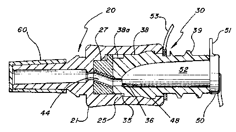
The medical connector 10 of the present invention is essentially a three
part connector comprising a valve housing 20 having a male Luer configured end
26
and a female Luer configured valve actuator 30 with a resilient valve element
40
which is compressed between a planar valve seat 22 in the housing 20 and a
planar
end wall 32 of the valve actuator 30.
The male Luer housing 20 and female Luer valve actuator 30 are
aligned on a common longitudinal axis and are rotatable with respect to each
other
about the longitudinal axis. A concave gripping surface 21 on the housing 20
facilitates fingertip operation of the connector.
The valve housing 20 has a fluid flow passage 24 therein which extends
longitudinally from the male Luer fluid line connection end 26 to the valve
seat 22.
Similarly, the valve actuator 30 has an axially extending female Luer fluid
flow
passage 34 therein which, in the embodiment shown, terminates in an off-center
positioned flow passage 36 in the end wall 32 of the valve actuator which
compressively engages the valve element 40. The actuator 30 is molded to have
a
smooth curved flow transition from axially extending flow passage 34 to off-
center
passage 36.
The valve element 40 has a fluid flow passageway 44 extending
SUBSTITUTE SHEET (RULE 26)
CA 02374846 2001-11-20
WO 01/23026 PCT/US99/12141
6
therethrough from an axially aligned opening in fluid communication with
passage 24
to an off-center positioned end 48 which can be placed into or out of flow
communication with off-center actuator passage 36. Valve element 40 is made of
a
firm but compressible elastomer which is compressed between the valve seat 22
in
the housing and the end wall 32 of the actuator during assembly of the valve.
Axial
compression of the elastomeric valve element 40 causes radial expansion of the
valve
element 40 into fluid tight engagement with the surrounding interior
cylindrical wall
of the housing 20 to provide a tight seal of the valve in open, closed and
intermediate
positions.
Restraining means on an interior cylindrical wall 28 proximate the open
end of the housing 20 and on an exterior cylindrical wall 38 of the valve
actuator in
the form of an annular bulge 39 on the actuator and mating receiving groove 29
on
the housing are dimensioned such that the valve element 40 is compressed to
the
appropriate extent as the bulge 39 seats itself in the groove 29 during valve
assembly.
Axial movement of the valve actuator 30 with respect to the housing 20 is thus
prevented during operation of the valve. Preferably, abutting radially
extending
surfaces on the bulge 39 and groove 29 are provided at the location shown to
prevent
inadvertent withdrawal of the actuator 30 from the housing 20 after the valve
has
been assembled. Relative rotation between the housing and actuator is,
however,
permitted. Preferably, a rigid sleeve 46 is provided in the flow passage 44 in
the
resilient valve element 40 to minimize radial collapse thereof during axial
compression of the valve element as the parts of the medical connector are
assembled.
Sleeve 46, if provided, also prevents all contact of the elastomeric valve
element with
fluid flow through the connector thus avoiding any possibility of
contamination of the
fluid by the elastomer or coagulation of blood or other fluid proximate the
elastomer.
Valve open and valve closed positioning means in the form of a molded
SUBSTITUTE SHEET (RULE 26)
CA 02374846 2001-11-20
WO 01/23026 PCT/US99/12141
7
long finger 25 on the housing 20 which is received in one or the other of
diametrically opposed finger positioning grooves 35 molded in the actuator 30
hold
the actuator relative to the housing in either a valve open position or in a
valve closed
position. The inherent resiliency of the plastic materials of which the
housing 20 and
valve actuator 30 are made permit the long finger 25 to snap into one or the
other of
the grooves 35 when the valve is either in the open or closed position while
permitting relatively easy manual rotation of the valve actuator 30 relative
to the
housing 20. The valve element 40 also has a single longitudinally extending
groove
45 which receives the long positioning finger 25 on the housing. As seen in
Figs. 2
and 7, the exterior cylindrical surface 38 on the actuator 30 extends in
excess of 180
proximate the grooves 35 to an annular reduced radius recess 38a of
approximately
the same depth as grooves 35 to permit the long finger 25 to be received in
the
annular gap between reduced radius recess 38a and interior housing wall 28 as
the
actuator 30 is rotated clockwise relative to the housing (as viewed from the
actuator
end) to open the fluid connection. Radially extending protuberances 38b
between the
grooves 35 and the recess 38a engage the finger 25 but permit movement of the
finger 25 over the protuberances 38b as the connector parts are relatively
rotated to
open or close the valve so as to provide the user with a "feel" to determine
if the
valve is in its open or closed position. The full radius portion of surface 38
which
extends in excess of 180 prevents further clockwise rotation of the actuator
30
relative to the housing by interference with long finger 25 and requires
counterclockwise movement of the actuator relative to the housing to close the
fluid
connection.
Relative rotation between the valve element 40 and the housing 20 is
prevented at all times by mating short fingers 27 molded on the housing which
are
receivable in short longitudinally extending grooves 47 molded in the valve
element.
Although three short fingers 27 and grooves 47 are provided to prevent
relative
SUBSTITUTE SHEET (RULE 26)
CA 02374846 2001-11-20
WO 01/23026 PCT/US99/12141
8
rotation between the valve element and the housing 20, as will be apparent,
other
configurations of mating projections and recesses or adhesive could be used
instead
to affix the valve element 40 to the valve seat 22 in housing 20. The length
of the
short fingers 27 is less than the longitudinal length of the grooves 47 on the
valve
element 40 to freely permit compression of the valve element 40 during
assembly
without interference between the ends of the fingers 27 and the ends of the
grooves
47.
As best seen in Figures 3 and 4, the off-center end 48 of the flow
passageway 44 through the valve element 40 is positionable in either a valve
closed
position (Figure 3) or a valve open position (Figure 4) upon rotation of the
valve
actuator 30 through an angle of somewhat less than 180 relative to the
housing 20.
As shown, the valve actuator 30 has a female Luer tapered receptacle
with external threads 37 thereon and the housing 20 has a male tapered Luer
flowline
connection end 26 provided with a restraining groove 29 for receiving an
annular boss
on a conventional internally threaded fluid connector line swivel (not shown)
which
permits threaded connections to a flow line to be made or broken without
twisting of
the flowline. Preferably, the actuator 30 and the housing 20 are formed of
medical
grade polycarbonate and the valve element 40 is preferably formed of medical
grade
polyisoprene.
Either or both of a removable plastic plug 50 which also fulfills the
functions of a cleansing swab, and a male end Luer contamination cap 60 may
optionally be provided for sealing opposite ends of the medical connector
during
shipment or otherwise. Plug 50 has a finger grip tab 51 and a male tapered end
52
of variable diameter and length which is formed of a soft plastic and is
snugly
received in tapered female Luer passageway 34 such that plug 50 may be
manually
SUBSTTTUTE SHEET (RULE 26)
CA 02374846 2001-11-20
WO 01/23026 PCT/US99/12141
9
rotated during insertion into passage 34 to swab the passageway all the way to
opening to passage 36 with alcohol after disconnection of actuator 30 from an
associated flowline. Finger tab 51 permits the plug 50 to be gripped without
contamination of the tapered end 52. A plastic tie loop 53 integrally formed
with the
plug 50 removably affixes the plug to the actuator 30. It will be noted that
disconnection of the connector requires counterclockwise rotation of the
female
threaded line receptacle relative to the actuator 30. The connector is
configured such
that counterclockwise rotation first causes the actuator 30 to move to the
valve closed
position before further counterclockwise rotation removes the flowline
connector from
the conventional clockwise threads 39. Alternatively, the flowline connections
can
be made or broken by longitudinal insertion or removal of male or female
flowline
Luer connectors from the female passageway 34 or the male end 26.
The medical connector described and claimed herein is particularly
advantageous in that it does not involve the use of any sharp pointed objects
such as
needles or cannulas. The longitudinally elongated configuration of the
connector
makes it particularly useful as a replacement for stopcock connectors on a
manifold
because the radially protruding handle of a stopcock frequently is positioned
too close
to an adjoining stopcock handle for easy manipulation without interference.
Figures 9 and 10 show a modified housing 20 having an integrally
formed internally threaded skirt portion 70 provided with internal threads 72
for
receiving a flowline coupling to form a male Luer lock. Housing 20 may also be
provided with longitudinally extending non-slip grooves 74 on the exterior of
the
concave finger gripping exterior surface.
Figures 11 and 12 show an optional elastomeric safety stopper 80
comprising a generally cylindrical collar 82 and an integrally formed conical
tapered
SUBSTITUTE SHEET (RULE 26)
CA 02374846 2001-11-20
WO 01/23026 PCT/US99/12141
skirt 84. The stopper 80 also has a slitted swabbable outer flap 86 at its
outer end
and a slitted inner flap 88 closing the inner end of the conical tapered skirt
84.
Stopper 80 is positioned, preferably by slight stretching, over the open
female Luer
end of the valve actuator 30 and is permanently adhesively bonded thereto. A
5 peripheral barb 90 may be formed on the end of the valve actuator 30 to
further assist
in preventing removal of the safety stopper 80 from the end of the valve
actuator 30.
The stopper 80 provides an extra safety feature to prevent inadvertent
backflow of blood or other bodily fluid from a patient when a male slip Luer
10 connector end of an IV or other fluid flow line is withdrawn from the
female Luer
flow passage 34. As discussed above, when disconnecting a threaded Leuer lock
flowline, the connector is designed to require automatic closure of the valve
to
prevent escape of any backflow of fluid from the patient. However, when a slip
Luer
connector instead of a threaded Luer lock is used on the fluid supply line, it
is
sometimes possible for a disconnection to be made without first rotating the
connector
to the valve closed position. The safety stopper 80 is designed to receive a
male slip
Luer connector through the slitted flap 86 with the four pie shaped flap
segments
bending inwardly as the male Luer connector is inserted to rest against the
inside wall
of the female Luer passage 34 in the valve actuator. Although four separate
segments are shown in each of the flaps 86, 88, the actual number will be
determined
by the product designer.
A tapered annular clearance space (not shown) may also be provided
in the inside wall of passage 34 to receive and contain the segments of the
flap 86
when the male slip Luer is inserted. The thickness of the clearance space may
be
designed to accommodate the combined wall thickness of the skirt 84 and
segments
of the flap 86 so that the interior cross-section of the female Luer passage
34 is
substantially the same as that of a conventional standard female Luer passage
not
SUBSTITUTE SHEET (RULE 26)
CA 02374846 2001-11-20
WO 01/23026 PCT/US99/12141
11
provided with a safety stopper.
Flow of IV or other fluid to the patient is permitted through the slitted
inner flap 88 in the left to right direction as seen in Fig. 11 due to
pressure
differential established during supply of fluid to the patient but is
prevented in the
reverse direction when the fluid line connection is broken even if the valve
inadvertently remains open. Backflow is doubly prevented by automatic
substantially
full closure of the inner flap 88 and by substantially full closure of the
outer flap 86
(when the male Luer connector is removed) resulting from inherent resiliency
of the
stopper material. The stopper 80 may be made of any suitable elastomer such as
polyisoprene or silicone rubber which is beneficial because it is also
inherently
lubricous. In addition, the substantially flat exterior surface of the outer
flap 86 is
easily cleaned or disinfected with a conventional swab which need not enter
into the
female Luer passage 34 where inadvertently deposited swab material is not
easily seen
and may not be removed.
Figs. 13 and 14 show a modified stopper 80 which does not have the
tapered skirt 84 and the extra backflow seal provided thereby but which
otherwise
operates substantially the same as the stopper shown in Figs. 12a and 12b. The
stopper 80 of Figs. 13 and 14 has a slightly thickened or conical flap 86
comprised
of four segments which, when folded against the inner wall of passageway 34 by
insertion of the male Luer connector, form a taper angle which is
substantially the
same as the taper angle of the male Luer connector. In each of the embodiments
of
the stopper shown, preferably the total length of each of the crossed slits in
the outer
flap 86 is about 0. 160" which is slightly less than the maximum diameter of a
standard male Luer connector (0.169").
While the foregoing constitutes a complete description of the preferred
SUBSTITUTE SHEET (RULE 26)
CA 02374846 2001-11-20
WO 01/23026 PCT/US99/12141
12
embodiment, it will be appreciated by persons skilled in the art that
modifications can
be made from the preferred embodiment and the scope of protection is to be
evaluated
solely with respect to the attached claims. For example, the valve element 40
may
instead be non-rotatably affixed to the end of the valve actuator 30 and the
eccentric
end 45 of the flow passage through the valve element can face the housing 20
rather
than face the actuator 30.
SUBSTITUTE SHEET (RULE 26)