Language selection

Search

Patent 2374886 Summary

Third-party information liability

Some of the information on this Web page has been provided by external sources. The Government of Canada is not responsible for the accuracy, reliability or currency of the information supplied by external sources. Users wishing to rely upon this information should consult directly with the source of the information. Content provided by external sources is not subject to official languages, privacy and accessibility requirements.

Claims and Abstract availability

Any discrepancies in the text and image of the Claims and Abstract are due to differing posting times. Text of the Claims and Abstract are posted:

  • At the time the application is open to public inspection;
  • At the time of issue of the patent (grant).
(12) Patent: (11) CA 2374886
(54) English Title: AIR TURNING BAR
(54) French Title: BARRE DE RETOURNEMENT PNEUMATIQUE
Status: Expired and beyond the Period of Reversal
Bibliographic Data
(51) International Patent Classification (IPC):
  • B29C 55/28 (2006.01)
  • B65H 23/32 (2006.01)
  • C08J 5/18 (2006.01)
(72) Inventors :
  • GANDELHEIDT, EDGAR (Germany)
(73) Owners :
  • KIEFEL EXTRUSION GMBH
(71) Applicants :
  • KIEFEL EXTRUSION GMBH (Germany)
(74) Agent: SMART & BIGGAR LP
(74) Associate agent:
(45) Issued: 2006-05-30
(22) Filed Date: 2002-03-06
(41) Open to Public Inspection: 2002-09-28
Examination requested: 2002-06-20
Availability of licence: N/A
Dedicated to the Public: N/A
(25) Language of filing: English

Patent Cooperation Treaty (PCT): No

(30) Application Priority Data:
Application No. Country/Territory Date
101 15 259.0 (Germany) 2001-03-28

Abstracts

English Abstract


An air turning bar for a take-off device for
plastic films has a hollow cylindrical body having a
depression in the region of the bar around which the film is
wrapped. The remaining region of the bar is circular
cylindrical. Air outlet openings are provided within the
depression. Narrow circular cylindrical strips adjoin the
ends of the depression which are provided in the
longitudinal direction of the air turning bar.


Claims

Note: Claims are shown in the official language in which they were submitted.

-5-
CLAIMS:
1. An air turning bar for a take-off device for the
transport of plastic film therearound, comprising a bar
having a circular cylindrical circumferential surface and a
region of said circumferential surface around which the
plastic film is wrapped during the transport thereof, said
bar defining air outlet openings which open in the region of
said circumferential surface around which the plastic film
is wrapped, and said bar further defining a depression
formed in the region of the circular cylindrical
circumferential surface around which the plastic film is
wrapped relative to a remaining circular cylindrical
circumference of said bar.
2. The air turning bar of claim 1, wherein said bar
comprises a hollow bar and said depression comprises a
pressed-in section of said hollow bar.
3. The air turning bar of claim 1, wherein said
depression comprises a recess formed in said circular
cylindrical circumferential surface.
4. The air turning bar of claim 1, wherein said bar
comprises a longitudinal axis and longitudinal ends and said
bar comprises sections at both longitudinal ends of the
depression having circular cylindrical circumferences.
5. The air turning bar of claim 1, wherein said bar
further defines a rounded transitional region between said
depression and said circular cylindrical circumferential
surface.
6. The air turning bar of claim 1, wherein said bar
further defines a sharp edge between said depression and
said circular cylindrical circumferential surface.

-6-
7. The air turning bar of claim 1, wherein said
depression comprises a longitudinal axis and at least
portion of said air outlet openings are arranged in row
along said longitudinal axis of said depression.
8. The air turning bar of claim 7, wherein said air
outlet openings are distributed within a surface of the
depression.
9. The air turning bar of claim 1, wherein said air
outlet openings are distributed within a surface of the
depression.
10. The air turning bar of claim 1, wherein said bar
is rotatable for directing the region of said
circumferential surface around which the plastic film is
wrapped.

Description

Note: Descriptions are shown in the official language in which they were submitted.


CA 02374886 2005-03-08
30698-9
- 1 -
AIR TURNING BAR
The invention relates to an air turning bar for a take -
off device for plastic films, in which air outlet
openings are provided in that region of its
circumferential surface around which the plastic film
is wrapped during its transportation.
In the case of an air turning bar which is disclosed in E~zropean
Patent No. EP 0 992 334 B1, in order to produce an air cushion in
the wrapping region of the plastic film, the said air
turning bar is bent over its entire le ngth and is set
in such a manner that the concave side is situated
essentially at the vertex of the deflection. This
produces a relatively large cavity between the film and
the air turning bar, a lot of compressed air being
required in order to fill the sa id cavity. Furthermore,
the bending of the air turning bar means that the side
borders of the film have only a relatively smell border
region which is suitable for sealing the air cushion.
Furthermore, it is difficult to produce uniform bending
of the air turning bar. Finally, the bending of the air
turning bar means that, during an adjustment in the
circumferential direction, problems may occur in an
undesirable manner because of contact between the film
and the air turning bar.
An aspect of the invention is to provide an air
turning bar, in which an air cushion region which can
be delimited precisely can be provided without the
disadvantages of a bent air turning bar in terms of its
production and its limitations having to be accepted
during an adjustment in the circumferential direction.

CA 02374886 2005-03-08
30698-9
- la -
According to a broad aspect of the invention,
there is provided an air turning bar for a take-off device
for the transport of plastic film therearound, comprising a
bar having a circular cylindrical circumferential surface
and a region of said circumferential surface around which
the plastic film is wrapped during the transport thereof,
said bar defining air outlet openings which open in the
region of said circumferential surface around which the
plastic film is wrapped, and said bar further defining a
depression formed in the region of the circular cylindrical
circumferential surface around which the plastic film is
wrapped relative to a remaining circular cylindrical
circumference of said bar.

CA 02374886 2005-03-08
30698-9
_ 2 _
A depression in the air turning bar can be adapted to
the particular requirements without a deviation from
. the circular cylindrical shape of the air turning bar
being present in the remaining r egion, which deviation
could initiate possible disturbances with regard to the
surrounding plastic film. Furthermore, the insertion of
a depression can be brought about mope simply than the
bending of an entire bar, and, specifically, in a
predetermined, a xact shape. The depression enables the
air cushion space to be designed in accordance with the
requirements, which is not possible to this extent with
bending of the air turning bar, because the air cushion
space has inevitable, different dimensions in thi ckness
along the air turning bar due to the bending. The
depression can be.adapted in its shape and depth to the
particular conditions without the remaining
circumference of the air turning bar being influenced.
In a development of the invention, the depr ession can
be produced by pressing in a hollow air turning bar, or
there is also the possibility of producing the
depression by a recess.
A further, advantageous refinement of the invention
2S consists in the air turning bar having, at the ends of
the depres lion, as seen in the longitudinal direction
of the air turning bar, a respective strip having a
circular cylindrical circumference. In contrast to a
bent air turning bar, this enables a relatively great
resistance to be set in the border region against air
flowing off in the longitudinal direction of the air
turning bar and therefore enables leakage losses to be
reduced. Depending on the requirements present in each
case, the depression may have, at its border, a rounded

CA 02374886 2002-03-06
- 3 -
transitional region to the circular cylindrical region
or the depression may be bounded at its border by a
sharp edge. These design possibilities are not provided
in the case of an air turning bar bent in its entirety.
The depression may have at least one row of air outlet
openings orientat ed in the longitudinal direction of
the depression or a plurality of air outlet openings
may be distributed over the surface of the depression,
which can depend on the shape of the depression, the
size of the air outlet openings, the width of the
plastic film to be taken off, etc.
If, in a development of the invention, the air turning
bar can be rotated and secured in the circumferential
direction, then the position of the depression with
respect to the plastic film, and therefore the
influence of the air cushion on the plastic film, can
be changed.
The invention will be explained in greater detail below
with reference to an exemplary embodiment. In the
drawing:
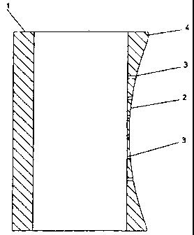
Figure 1 shows a plan view of an air turning bar;
Figure 2 shows a section along the line II -II in
Figure 1;
Figure 3 shows a section along the line III -III in
Figure 1; and
Figure 4 shows a side view.
As can be seen from the graphical illustration, an air
turning bar 1 has a cylindrical hollow body which has a
depression 2 in a certain region, which forms the
wrapping region for a plastic film (not illustrated) to
be transported, which depression, as seen in the

CA 02374886 2002-03-06
- 4 -
longitudinal direction of the air turning bar 1, has a
row of air outlet openings 3 which produce an air
cushion in the region of this depression 2 in order to
avoid the plastic film which is to be transported
bearing against the air turning bar. At each end of the
depression 2 there remains, as seen in the longitudinal
direction, a narrow region which is denoted by 4 and
which has the c ustomary, circular cylindrical cross
section of the air turning bar and which ensures a
reduction in leakage losses. A transitional region,
which is denoted by 5, from the depression to the
circular cylindrical circumference 6 is denoted by 5
and has a rou nded design in the exemplary embodiment
illustrated.

Representative Drawing
A single figure which represents the drawing illustrating the invention.
Administrative Status

2024-08-01:As part of the Next Generation Patents (NGP) transition, the Canadian Patents Database (CPD) now contains a more detailed Event History, which replicates the Event Log of our new back-office solution.

Please note that "Inactive:" events refers to events no longer in use in our new back-office solution.

For a clearer understanding of the status of the application/patent presented on this page, the site Disclaimer , as well as the definitions for Patent , Event History , Maintenance Fee  and Payment History  should be consulted.

Event History

Description Date
Inactive: IPC expired 2019-01-01
Time Limit for Reversal Expired 2011-03-07
Letter Sent 2010-03-08
Grant by Issuance 2006-05-30
Inactive: Cover page published 2006-05-29
Inactive: Final fee received 2006-03-20
Pre-grant 2006-03-20
Inactive: IPC from MCD 2006-03-12
Notice of Allowance is Issued 2006-02-13
Letter Sent 2006-02-13
Notice of Allowance is Issued 2006-02-13
Inactive: Approved for allowance (AFA) 2005-09-07
Amendment Received - Voluntary Amendment 2005-03-08
Inactive: S.30(2) Rules - Examiner requisition 2004-09-09
Application Published (Open to Public Inspection) 2002-09-28
Inactive: Cover page published 2002-09-27
Letter Sent 2002-09-09
Letter Sent 2002-08-20
Amendment Received - Voluntary Amendment 2002-07-30
Inactive: Single transfer 2002-07-16
All Requirements for Examination Determined Compliant 2002-06-20
Request for Examination Requirements Determined Compliant 2002-06-20
Request for Examination Received 2002-06-20
Inactive: First IPC assigned 2002-05-16
Inactive: IPC assigned 2002-05-16
Inactive: Courtesy letter - Evidence 2002-04-09
Application Received - Regular National 2002-04-05
Filing Requirements Determined Compliant 2002-04-05
Inactive: Filing certificate - No RFE (English) 2002-04-05
Change of Address or Method of Correspondence Request Received 2002-03-25

Abandonment History

There is no abandonment history.

Maintenance Fee

The last payment was received on 2006-03-01

Note : If the full payment has not been received on or before the date indicated, a further fee may be required which may be one of the following

  • the reinstatement fee;
  • the late payment fee; or
  • additional fee to reverse deemed expiry.

Please refer to the CIPO Patent Fees web page to see all current fee amounts.

Fee History

Fee Type Anniversary Year Due Date Paid Date
Application fee - standard 2002-03-06
Request for examination - standard 2002-06-20
Registration of a document 2002-07-16
MF (application, 2nd anniv.) - standard 02 2004-03-08 2004-02-13
MF (application, 3rd anniv.) - standard 03 2005-03-07 2005-02-24
MF (application, 4th anniv.) - standard 04 2006-03-06 2006-03-01
Final fee - standard 2006-03-20
MF (patent, 5th anniv.) - standard 2007-03-06 2007-02-21
MF (patent, 6th anniv.) - standard 2008-03-06 2008-02-21
MF (patent, 7th anniv.) - standard 2009-03-06 2009-03-02
Owners on Record

Note: Records showing the ownership history in alphabetical order.

Current Owners on Record
KIEFEL EXTRUSION GMBH
Past Owners on Record
EDGAR GANDELHEIDT
Past Owners that do not appear in the "Owners on Record" listing will appear in other documentation within the application.
Documents

To view selected files, please enter reCAPTCHA code :


To view images, click a link in the Document Description column. To download the documents, select one or more checkboxes in the first column and then click the "Download Selected in PDF format (Zip Archive)" or the "Download Selected as Single PDF" button.

List of published and non-published patent-specific documents on the CPD .

If you have any difficulty accessing content, you can call the Client Service Centre at 1-866-997-1936 or send them an e-mail at CIPO Client Service Centre.


Document
Description 
Date
(yyyy-mm-dd) 
Number of pages   Size of Image (KB) 
Representative drawing 2002-05-17 1 5
Abstract 2002-03-06 1 15
Description 2002-03-06 4 154
Claims 2002-03-06 2 51
Drawings 2002-03-06 2 28
Cover Page 2002-09-06 1 29
Abstract 2005-03-08 1 12
Description 2005-03-08 5 164
Claims 2005-03-08 2 55
Drawings 2005-03-08 4 33
Representative drawing 2006-05-10 1 6
Cover Page 2006-05-10 1 31
Filing Certificate (English) 2002-04-05 1 164
Acknowledgement of Request for Examination 2002-08-20 1 177
Courtesy - Certificate of registration (related document(s)) 2002-09-09 1 112
Reminder of maintenance fee due 2003-11-10 1 106
Commissioner's Notice - Application Found Allowable 2006-02-13 1 161
Maintenance Fee Notice 2010-04-19 1 171
Correspondence 2002-04-05 1 23
Correspondence 2002-03-25 1 41
Fees 2006-03-01 1 35
Correspondence 2006-03-20 1 37