Some of the information on this Web page has been provided by external sources. The Government of Canada is not responsible for the accuracy, reliability or currency of the information supplied by external sources. Users wishing to rely upon this information should consult directly with the source of the information. Content provided by external sources is not subject to official languages, privacy and accessibility requirements.
Any discrepancies in the text and image of the Claims and Abstract are due to differing posting times. Text of the Claims and Abstract are posted:
| (12) Patent: | (11) CA 2375308 |
|---|---|
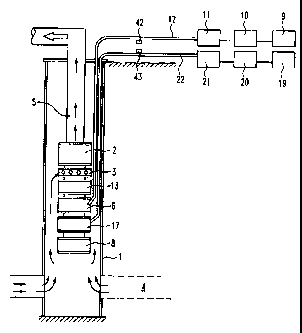
| (54) English Title: | SYSTEM FOR AND A METHOD OF PUMPING FLUIDS FROM A WELL |
| (54) French Title: | SYSTEME ET METHODE DE POMPAGE DE LIQUIDES D'UN PUITS |
| Status: | Term Expired - Post Grant Beyond Limit |
| (51) International Patent Classification (IPC): |
|
|---|---|
| (72) Inventors : |
|
| (73) Owners : |
|
| (71) Applicants : |
|
| (74) Agent: | |
| (74) Associate agent: | |
| (45) Issued: | 2006-04-18 |
| (22) Filed Date: | 2002-03-08 |
| (41) Open to Public Inspection: | 2003-06-26 |
| Examination requested: | 2002-03-08 |
| Availability of licence: | N/A |
| Dedicated to the Public: | N/A |
| (25) Language of filing: | English |
| Patent Cooperation Treaty (PCT): | No |
|---|
| (30) Application Priority Data: | ||||||
|---|---|---|---|---|---|---|
|
A system for pumping fluid from a well has a submersible pump introducible into a well for pumping fluid from the well to ground, submersible motor introducible into the well and connected to the submersible pump for driving the submersible pump, the motor including at least one upper tandem motor mechanically connectable to another motor and electrically connectable to a power source, and at least one additional upper tandem motor, the additional upper tandem motor being mechanically connected with the first mentioned upper tandem motor so as to drive the submersible pump with a mechanical power derived from the first mentioned upper tandem motor and the additional upper tandem motor, and a power supply which independently supplies electrical power to the upper tandem motors.
Système de pompage d'un fluide à partir d'un puits, ayant une pompe submersible qui peut être introduite dans un puits pour pomper du fluide du puits jusqu'au sol, un moteur submersible qui peut être introduit dans le puits et raccordé à la pompe submersible pour entraîner la pompe submersible, le moteur incluant au moins un moteur tandem supérieur qui peut être raccordé mécaniquement à un autre moteur et relié électriquement à une alimentation, et au moins un moteur tandem supérieur supplémentaire, le moteur tandem supérieur supplémentaire étant raccordé mécaniquement au premier moteur tandem supérieur mentionné de façon à entraîner la pompe submersible avec une puissance mécanique dérivée du premier moteur tandem supérieur mentionné et du moteur tandem supérieur supplémentaire, et une alimentation qui fournit indépendamment de l'énergie électrique aux moteurs tandem supérieurs.
Note: Claims are shown in the official language in which they were submitted.
Note: Descriptions are shown in the official language in which they were submitted.
2024-08-01:As part of the Next Generation Patents (NGP) transition, the Canadian Patents Database (CPD) now contains a more detailed Event History, which replicates the Event Log of our new back-office solution.
Please note that "Inactive:" events refers to events no longer in use in our new back-office solution.
For a clearer understanding of the status of the application/patent presented on this page, the site Disclaimer , as well as the definitions for Patent , Event History , Maintenance Fee and Payment History should be consulted.
| Description | Date |
|---|---|
| Inactive: Expired (new Act pat) | 2022-03-08 |
| Common Representative Appointed | 2019-10-30 |
| Common Representative Appointed | 2019-10-30 |
| Maintenance Request Received | 2017-01-16 |
| Inactive: Office letter | 2016-06-10 |
| Maintenance Request Received | 2016-03-01 |
| Maintenance Request Received | 2014-12-23 |
| Maintenance Request Received | 2013-12-19 |
| Maintenance Request Received | 2013-01-03 |
| Grant by Issuance | 2006-04-18 |
| Inactive: Cover page published | 2006-04-17 |
| Inactive: IPC from MCD | 2006-03-12 |
| Inactive: IPC from MCD | 2006-03-12 |
| Inactive: IPC from MCD | 2006-03-12 |
| Pre-grant | 2006-01-06 |
| Inactive: Final fee received | 2006-01-06 |
| Notice of Allowance is Issued | 2005-11-09 |
| Notice of Allowance is Issued | 2005-11-09 |
| Letter Sent | 2005-11-09 |
| Inactive: Approved for allowance (AFA) | 2005-10-31 |
| Amendment Received - Voluntary Amendment | 2005-10-07 |
| Amendment Received - Voluntary Amendment | 2005-09-23 |
| Amendment Received - Voluntary Amendment | 2005-04-04 |
| Inactive: S.30(2) Rules - Examiner requisition | 2005-02-01 |
| Application Published (Open to Public Inspection) | 2003-06-26 |
| Inactive: Cover page published | 2003-06-25 |
| Letter Sent | 2002-09-13 |
| Inactive: Correspondence - Transfer | 2002-07-18 |
| Inactive: Office letter | 2002-07-04 |
| Inactive: First IPC assigned | 2002-06-07 |
| Inactive: Correspondence - Formalities | 2002-05-30 |
| Inactive: Single transfer | 2002-05-10 |
| Application Received - Regular National | 2002-04-09 |
| Letter Sent | 2002-04-09 |
| Inactive: Filing certificate - RFE (English) | 2002-04-09 |
| Request for Examination Requirements Determined Compliant | 2002-03-08 |
| Small Entity Declaration Determined Compliant | 2002-03-08 |
| All Requirements for Examination Determined Compliant | 2002-03-08 |
There is no abandonment history.
The last payment was received on 2006-01-27
Note : If the full payment has not been received on or before the date indicated, a further fee may be required which may be one of the following
Patent fees are adjusted on the 1st of January every year. The amounts above are the current amounts if received by December 31 of the current year.
Please refer to the CIPO
Patent Fees
web page to see all current fee amounts.
Note: Records showing the ownership history in alphabetical order.
| Current Owners on Record |
|---|
| FOUNDATION ENTERPRISES LTD. |
| Past Owners on Record |
|---|
| DANA ROBERT PETTIGREW |

