Language selection

Search

Patent 2375710 Summary

Third-party information liability

Some of the information on this Web page has been provided by external sources. The Government of Canada is not responsible for the accuracy, reliability or currency of the information supplied by external sources. Users wishing to rely upon this information should consult directly with the source of the information. Content provided by external sources is not subject to official languages, privacy and accessibility requirements.

Claims and Abstract availability

Any discrepancies in the text and image of the Claims and Abstract are due to differing posting times. Text of the Claims and Abstract are posted:

  • At the time the application is open to public inspection;
  • At the time of issue of the patent (grant).
(12) Patent Application: (11) CA 2375710
(54) English Title: METHOD AND ARRANGEMENT RELATING TO A SWING DAMPER
(54) French Title: PROCEDE ET MECANISME D'AMORTISSEUR D'OSCILLATION
Status: Deemed Abandoned and Beyond the Period of Reinstatement - Pending Response to Notice of Disregarded Communication
Bibliographic Data
(51) International Patent Classification (IPC):
  • B66C 3/00 (2006.01)
  • B66C 13/06 (2006.01)
  • F16F 7/04 (2006.01)
  • F16F 7/06 (2006.01)
(72) Inventors :
  • HARR, JOAKIM (Sweden)
  • JONSSON, ANDERS (Sweden)
  • JONSSON, CHRISTER (Sweden)
(73) Owners :
  • INDEXATOR AB
(71) Applicants :
  • INDEXATOR AB (Sweden)
(74) Agent: SMART & BIGGAR LP
(74) Associate agent:
(45) Issued:
(86) PCT Filing Date: 2000-05-28
(87) Open to Public Inspection: 2000-12-07
Availability of licence: N/A
Dedicated to the Public: N/A
(25) Language of filing: English

Patent Cooperation Treaty (PCT): Yes
(86) PCT Filing Number: PCT/SE2000/001096
(87) International Publication Number: WO 2000073195
(85) National Entry: 2001-11-28

(30) Application Priority Data:
Application No. Country/Territory Date
9901982-0 (Sweden) 1999-05-31

Abstracts

English Abstract


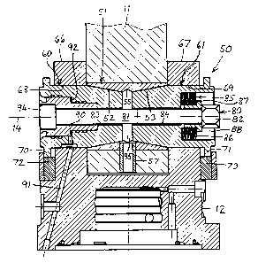
The invention relates to an arrangement and to a method related to a swing
damper, particularly to a swing damper (1) for supporting a tool (5) that
hangs from a crane arm (2) or some similar structure. The swing damper (1)
includes an upper part (11), which is connected to the crane arm (2), and a
lower part (12) that carries a work tool (5) or some similar device either
directly or via a rotator (4) for instance. The upper part (11) and the lower
part (12) are pivotally interconnected via a pivot joint (13), wherewith the
swing damper (1) includes a brake arrangement (50) in the form of a male-
female-cone arrangement. Either the upper part (11) or the lower part (12)
carries two mutually opposing female cones (52, 53). The part that lacks the
female cones carries two mutually opposing male cone parts (60, 61). The
conical surfaces of the male cone parts and the female cones are in mutual
contact in effecting a braking operation, and the conical surfaces of the male
cone parts and the female cones also function as bearing surfaces between the
upper part (11) and the lower part (12). An outer portion (64, 65) of the male
cone parts (60, 61) functions to transfer load to that part which lacks said
female cones (52, 53).


French Abstract

La présente invention concerne un mécanisme et un procédé associés à un amortisseur d'oscillation, en particulier à un amortisseur d'oscillation (1) destiné à supporter un outil (5) suspendu depuis le bras (2) d'une grue ou une structure similaire. L'amortisseur d'oscillation (1) comprend une partie supérieure (11) qui est raccordée au bras de grue (2), et une partie inférieure (12) qui porte un outil de travail (5) ou autre dispositif similaire, directement ou par l'entremise d'un rotateur (4), par exemple. Les parties supérieure (11) et inférieure (12) sont reliées de façon pivotante via une articulation à pivot (13), grâce à laquelle l'amortisseur d'oscillation (1) comprend un mécanisme de frein (50) se présentant sous la forme d'un agencement de cônes mâle-femelles (60,61). La partie supérieure (11) ou la partie inférieure (12) supporte deux cônes femelles (52,53) opposés l'un à l'autre. La partie qui ne supporte pas les cônes femelles supporte deux parties opposées de cône mâle (60,61). Les surfaces coniques des parties du cône mâle et des cônes femelles se trouvent en contact les unes avec les autres lors d'une opération de freinage, et elles fonctionnent également comme surfaces de roulement entre la partie supérieure (11) et la partie inférieure (12). Une section extérieure (64,65) des parties de cône mâle (60,61) sert à transférer la charge sur la partie qui ne supporte pas les cônes femelles (52,53).

Claims

Note: Claims are shown in the official language in which they were submitted.


1
CLAIMS
1. An arrangement relating to a swing damper, particularly
to a swing damper (1) for carrying a tool (5) that hangs from
a crane arm (2) or a similar device, wherein the swing damper
(1) includes an upper part (11) which is connected to the
crane arm (2), and a lower part (12) which carries a working
tool (5) or a similar device either directly or through the
medium of a rotator (4) for instance, wherein the upper part
(11) and the lower part (12) are pivotally interconnected via
a pivot joint (13), wherein the swing damper (1) includes a
brake arrangement (50) in the form of a male-female-cone
arrangement, either the upper part (11) or the lower part
(12) carries two mutually opposing female cones (52,53),
wherein the part which lacks the female cones carries two
mutually opposing male-cone parts (60,61), wherein the
conical surfaces of the male-cone parts and the female cones
are mutually in contact when effecting a braking action,
wherein the conical surfaces of the male-cone parts and
female cones also function as bearing surfaces between said
upper part (11) and said lower part (12), and wherein the
brake arrangement (50) includes a tensioning device (80)
which is adapted to exert a braking torque generating force
between the male cone parts (60,61), characterised in that
the male cone parts (60,61) have an outer portion (64,65)
which is in load transfer engagement with openings (68,69) in
that part that lacks said female cones (52,53); and in that a
radial gap is arranged between the tensioning device (80) and
one in the male cone parts (60,61) arranged axial through-
penetrating opening (83,84) for the tensioning device (80) so
that the tensioning device (80) is only subjected to axially
acting forces.

2
2. An arrangement according to Claim 1, characterised in
that the tensioning device (80) includes a screw (81) and a
nut (82).
3. An arrangement according to Claim 1 or 2, characterised
in that the tensioning device (80) includes a spring element
(85) and/or a pressure-medium manoeuvred force generator (90)
that acts between the male cone parts (60,61).
4. An arrangement according to any one of Claims 1-3,
characterised in that the male cone parts (60,61) are non-
rotatably connected to either the lower part (11) or to the
upper part (12) of said damper.
5. An arrangement according to any one of Claims 1-4,
characterised in that a part (51) or parts carrying the
female cones (52,53) is/are non-rotatably connected to the
upper part (11) or to the lower part (12) of said damper.
6. An arrangement according to Claim 5, characterised in
that the female cone part or parts includes/include a
longitudinally extending slot (54).
7. A method relating to a swing damper, particularly to a
swing damper (1) for carrying a tool (5) that hangs from a
crane arm (2) or a similar device, wherein the swing damper
(1) includes an upper part (11), which is connected to the
crane arm (2) and a lower part (12) which carries a working
tool (5) or a similar device either directly or via a rotator
(4) for instance, wherein the upper part (11) and the lower
part (12) are pivotally interconnected via a pivot joint

3
(13), wherein the swing damper (1) includes a brake
arrangement (50) in the form of a male-female-cone
arrangement, generating a swing damping effect through the
medium of two mutually opposing female cones (52,53) carried
by either the upper part (11) or the lower part (12), wherein
the part that lacks the female cones carries two mutually
opposing male cone parts (60,61), causing the conical
surfaces of the male cone parts and the female cones to
contact each other to produce a braking/damping effect and
causing the conical surfaces of the male cone parts and the
female cones to function as load carrying bearing surfaces
between the upper part (11) and the lower part (12) at the
same time, wherein the brake arrangement (50) includes a
tensioning device (80) which is adapted to exert a braking
torque generating force between the male cone parts (60,61),
characterised by causing an outer part (64,65) of the male
cone parts (60,61) to transfer load to that part which lacks
said female cones (52,53); and by arranging the tensioning
device (80) to only be subjected to axially acting forces.
8. A method according to Claim 7, characterised by exerting
said braking torque generating force with the aid of
mechanical means (85) and/or by pressure medium actuation.
9. A method according to Claim 7 or 8, characterised by
applying a friction influencing medium to the conical
surfaces of the male cone parts (60,61) and the female cones
(52,53).
10. The use of an arrangement according to any one of Claims
1-6, characterised in that the arrangement is used to dampen
or brake swinging of a suspended object (5). ------

Description

Note: Descriptions are shown in the official language in which they were submitted.


CA 02375710 2001-11-28
WO 00/73195 PCT/SE00/01096
METHOD AND ARRANGEMENT RELATING TO A SWING DAMPER
The present invention relates to a swing damper arrangement
according to the preamble of Claim 1. The invention also
relates to a method.
A swing damper is used in conjunction with supporting
different types of tools suspended, for instance, from a
crane arm or jib with the intention of effectively and
reliably braking or damping the pendular movement/swinging
movement that normally occurs when manoeuvring the crane arm
in connection with carrying out different tasks, for
instance.
Swing dampers can be used in connection with all conceivable
types of tools that are suspended from the tip of a crane
arm, for instance in connection with forest harvesters,
forwarders, forest processors, log cranes, excavating
machines, special duty machines, etc. The swing damper may
have both a single damping mode and a double damping mode,
i.e. it can dampen/brake pendular movement in one or two
pendulating/swinging planes.
An object of the present invention is to provide a highly
advantageous brake arrangement in a swing damper, and also to
provide a highly advantageous braking method. These objects
are achieved with an arrangement and a method that have the
characteristic features set forth in respective accompanying
Claims.
Listed below are a number of advantages afforded by the
invention.
A swing damper that includes an inventive arrangement is very
compact.

CA 02375710 2001-11-28
WO 00/73195 PCT/SE00/01096
There is obtained a smooth and uniform braking action with
even wear on those parts of the brake arrangement that are
prone to wear, and also a highly advantageous bearing from a
load carrying aspect, among other things.
The brake arrangement has a long useful life and long
intervals between adjustments are possible. The brake
arrangement can be readily serviced.
A desired basic braking torque setting can be easily achieved
and any subsequent adjustment necessary to the brake
arrangement can also be carried out very readily.
Inventive arrangements can be used in swing dampers of both
single and double mode types.
The inventive arrangement also has technical and economical
advantages.
The invention will now be described in more detail with
reference to exemplifying embodiments thereof and also with
reference to the accompanying drawings, in which Fig. 1 is a
perspective view of an inventive arrangement mounted on the
tip of a crane arm and carrying a gripping tool; Fig. 2 is an
exploded perspective view of a swing damper that includes an
inventive arrangement; and Fig. 3 is a vertical section view
of said arrangement.
Fig. 1 shows an inventive swing damper 1 pivotally mounted on
the tip of a crane arm 2 through the medium of a swing
joint/bearing 3. The swing damper 1 carries at its lower end
a rotator 4, which, in turn, carries a tool in the form of a
gripper 5.
The bearing 3 allows free pendulating movement/swinging
movement about a shaft or axis 6, and the rotator 4 of the

CA 02375710 2001-11-28
WO 00/73195 PCT/SE00/01096
3
illustrated embodiment is hydraulically operated and enables
the gripper 5 to be rotated in the performance of its duties.
The hydraulic hoses leading to the rotator and the gripper
have been omitted for the sake of clarity.
The swing damper 1 includes an upper part 11, which is freely
pivotally connected to the crane arm 2 via the bearing 3. The
swing damper 1 also includes a lower part 12 , which carries
the tool 5, for instance via the rotator 4. The upper part 11
includes an attachment lug 15, which co-acts with the bearing
3. The lower part 12 includes an attachment means 16 for the
rotator 4 or for direct attachment of the tool 5.
The upper part 11 and the lower part 12 of the swing damper
are pivotally connected to one another via a swing
joint/bearing 13, so as to be able to swing about a
shaft/axis 14. The pivot shaft 14 is generally perpendicular
to the pivot shaft 6. This contributes to the desired
mobility of the tool 5.
In order to enable the pendulating movement/swinging movement
of the tool 5 as the crane arm is manoeuvred to be dampened
relatively quickly, the swing damper 1 is provided with a
brake arrangement 50 whici. enables said pendulating
movement/swinging movement about the pivot shaft 14 to be
braked in a desired manner.
The brake arrangement 50 included in the swing damper 1 has
the form of a male-female-cone arrangement, which is
described in more detail hereinafter.
In the illustrated embodiment, the upper part 11 carries a
brake element 51 that includes two mutually facing female
cones 52, 53. The brake element 51 also includes a
longitudinally extending slot 54 and an internal, central
ring groove 55. The brake element 51 is placed in a

CA 02375710 2001-11-28
WO 00/73195 PCT/SE00/01096
4
corresponding hole 56 in the upper part 11 and fixed thereto
by means of a lock pin 57. The brake element 51 is thus non-
rotatably connected to the top part 11.
The lower part 12 carries two mutually facing male cone parts
60,61 which each have a conical portion 62,63 and a
cylindrical portion 64,65. The one male cone part 60 is non-
rotatably carried by an attachment lug 66 on the lower part
12 and the other male cone part 61 is non-rotatably carried
by an attachment lug 67 on the lower part 12. The attachment
lugs 66 and 67 have holes 68,69 which are in longitudinal
sliding co-action with the cylindrical portion 64,65 of the
male cone parts . Non-rotatable locking of said parts can be
achieved by the abutment of slide shoulders 70,71 against
anvil shoulders 72,73.
The brake arrangement 50 includes a tightening or tensioning
device 80 which functions to move the male cone parts 60, 61
towards each other. The tightening/tensioning device 80
includes a screw 81 and a nut 82, said screw 81 is extending
through a clearance hole 83,84 in the male cone parts 60,61.
The tensioning device 80 has at its nut end a spring element
85 that is comprised of mutually opposing cup springs 86, as
apparent from Fig. 3. When greater spring forces are desired,
the cup springs 86 can be grouped in a manner different to
that illustrated. The cup springs 86 are guided by a collared
guide sleeve 87 and are mounted in a recess 88 in the male
cone part 61.
A pressure-operated power generating means 90 is provided in
the male cone part 60. This power generator 90 is comprised
of a hydraulic piston to which pressure medium is supplied
through a delivery line 91, said medium entering through an
axial gap 92 located between the hydraulic piston 90 and a
recess 93 in the male cone part 60. The hydraulic piston 90
is held in place by the head 94 of the screw 81, as will be

WO 00/73195 CA 02375710 2001-11-28 pCT/SE00/01096
apparent from Fig. 3. The pressure medium is conveniently
delivered through the medium of a duct system that
communicates with the rotator.
5 The male cone parts 60 and 61 are thus held together by means
of the aforesaid screw-and-nut arrangement, said nut 82 being
tightened so as to compress the spring element 85 to an
extent at which an appropriate basic braking action is
obtained.
When necessary, the braking effect can be increased by
pressure adjustment with the aid of hydraulic oil introduced
through the axial gap 92 at the hydraulic piston 90, such as
to press the male cone parts 60,61 towards each other and
therewith decrease the gap 95 between the male cone parts in
keeping with wear and the contact pressure between the
conical surfaces of the male cones and the conical surfaces
of the female cones will be increased to an extent
corresponding to the desired braking effect.
It will be noted that the conical surfaces of the male cone
parts and the female cone parts also function as bearing
surfaces between the upper part 11 and the lower part 12. The
bearing 13 will thereby be very stable and the screw 81 is
relieved of the necessity to take-up transversally acting
forces. The bearing surfaces/brake surfaces may be oil
lubricated if so desired.
It will also be noted that the cylindrical portions 64,65 of
the male cone parts are in load transferring engagement with
the holes/openings 68,69 in the lower part 12.
Thus, swing damping is achieved by virtue of two mutually
opposing female cones 52,53 carried by said upper part 11 and
by virtue of two mutually opposing male cone parts 60,61
carried by the lower part 12, wherewith the conical surfaces

CA 02375710 2001-11-28
WO 00/73195 PCT/SE00/01096
6
of the male cone parts and the female cone parts are in
mutual contact to provide a braking effect and, at the same
time, function as load-carrying bearing surfaces between the
upper part 11 and the lower part 12. Braking is achieved by a
compressive force effect between the male cone parts 60,61.
This pressure force is achieved by means of mechanical
devices and/or by means of pressure medium actuation.
Slotted female cones provide a play-free bearing when the
brake arrangement 50 is tensioned/activated.
The slots 54 in the female cones coincide with the hole
centre of the lock pin 57.
A basic braking action is set by appropriate compression of
the spring element 85. An additional braking effect is
achieved by hydraulic actuation.
The male cone parts 60,61 have several functions; they
function as shaft bearings, brake elements, hydraulic
cylinders and wear limiting means.
With respect to the male cone parts, means which lock said
parts against rotation and which prevent separation of said
parts are provided.
The centre screw 81 is not subjected to any transversally
acting forces and the guide sleeve/spacer sleeve 87 limits
the magnitude to which the spring is tensioned and minimises
the risk of fatigue in the cup springs 86.
In the case of a simpler embodimer_t, the hydraulic piston 90
may be omitted so that solely the Force exerted by the spring
element 85 will be utilised in generating a braking torque.
In this respect, a spring element may be mounted within both
of the male cone parts 60,61 if so desired.

CA 02375710 2001-11-28
WO 00/73195 PCT/SE00/01096
7
In a further embodiment, the spring elements are excluded and
replaced by hydraulic piston means.
It will be noted that many constructive options exist within
the scope of the present invention.
The design and construction of the spring elements may also
vary widely within the scope of the invention.
In the case of the illustrated embodiment, the female cones
are carried by the upper part and the male cone parts by the
lower part. Naturally, the inventive arrangement may be
constructed such that the female cones are carried by the
lower part and the male cone parts are carried by the top
part.
Although the swing damper of the illustrated embodiment is a
single-type damper, it will be understood that inventive
arrangements can be used in double-type swing dampers,
wherein swinging of both the bearing 3 and the bearing 13 can
be dampened by means of inventive arrangements.
In an alternative embodiment, the lengths of the cylindrical
portions 64,65 of the male cone parts 60,61 may be such that
said portions extend into the end parts of the brake element
51 prior to the cylindrical portions 64, 65 merging with the
conical portions 62,63. In addition to its female cones
52,53, the brake element 51 also includes cylindrical end
parts for receiving end sections of the cylindrical portions
64,65 of the male cone parts 60,61. In the case of this
alternative embodiment, the inner surface of the brake
element includes both a cylindrical and a conical section.
It will be understood that described and illustrated
components can be replaced ~,aith functionally equivalent

CA 02375710 2001-11-28
WO 00/73195 PCT/SE00/01096
8
components within the concept of the invention. The choice of
materials used is, of course, also optional.
It shall thus be understood that the invention is not
restricted to the illustrated and described embodiments and
that changes and modifications can be made within the scope
of the accompanying Claims.

Representative Drawing
A single figure which represents the drawing illustrating the invention.
Administrative Status

2024-08-01:As part of the Next Generation Patents (NGP) transition, the Canadian Patents Database (CPD) now contains a more detailed Event History, which replicates the Event Log of our new back-office solution.

Please note that "Inactive:" events refers to events no longer in use in our new back-office solution.

For a clearer understanding of the status of the application/patent presented on this page, the site Disclaimer , as well as the definitions for Patent , Event History , Maintenance Fee  and Payment History  should be consulted.

Event History

Description Date
Inactive: IPC from MCD 2006-03-12
Application Not Reinstated by Deadline 2004-05-28
Time Limit for Reversal Expired 2004-05-28
Deemed Abandoned - Failure to Respond to Maintenance Fee Notice 2003-05-28
Letter Sent 2002-10-29
Inactive: Single transfer 2002-09-10
Inactive: Cover page published 2002-05-16
Inactive: Courtesy letter - Evidence 2002-05-14
Inactive: Notice - National entry - No RFE 2002-05-13
Application Received - PCT 2002-04-10
National Entry Requirements Determined Compliant 2001-11-28
Application Published (Open to Public Inspection) 2000-12-07

Abandonment History

Abandonment Date Reason Reinstatement Date
2003-05-28

Maintenance Fee

The last payment was received on 2002-05-24

Note : If the full payment has not been received on or before the date indicated, a further fee may be required which may be one of the following

  • the reinstatement fee;
  • the late payment fee; or
  • additional fee to reverse deemed expiry.

Please refer to the CIPO Patent Fees web page to see all current fee amounts.

Fee History

Fee Type Anniversary Year Due Date Paid Date
Basic national fee - standard 2001-11-28
MF (application, 2nd anniv.) - standard 02 2002-05-28 2002-05-24
Registration of a document 2002-09-10
Owners on Record

Note: Records showing the ownership history in alphabetical order.

Current Owners on Record
INDEXATOR AB
Past Owners on Record
ANDERS JONSSON
CHRISTER JONSSON
JOAKIM HARR
Past Owners that do not appear in the "Owners on Record" listing will appear in other documentation within the application.
Documents

To view selected files, please enter reCAPTCHA code :


To view images, click a link in the Document Description column. To download the documents, select one or more checkboxes in the first column and then click the "Download Selected in PDF format (Zip Archive)" or the "Download Selected as Single PDF" button.

List of published and non-published patent-specific documents on the CPD .

If you have any difficulty accessing content, you can call the Client Service Centre at 1-866-997-1936 or send them an e-mail at CIPO Client Service Centre.


Document
Description 
Date
(yyyy-mm-dd) 
Number of pages   Size of Image (KB) 
Representative drawing 2002-05-15 1 25
Abstract 2001-11-28 1 91
Claims 2001-11-28 3 154
Description 2001-11-28 8 298
Drawings 2001-11-28 3 77
Cover Page 2002-05-16 1 64
Reminder of maintenance fee due 2002-05-13 1 111
Notice of National Entry 2002-05-13 1 194
Courtesy - Certificate of registration (related document(s)) 2002-10-29 1 109
Courtesy - Abandonment Letter (Maintenance Fee) 2003-06-25 1 174
PCT 2001-11-28 11 441
Correspondence 2002-05-13 1 24
Fees 2002-05-24 1 33