Language selection

Search

Patent 2375794 Summary

Third-party information liability

Some of the information on this Web page has been provided by external sources. The Government of Canada is not responsible for the accuracy, reliability or currency of the information supplied by external sources. Users wishing to rely upon this information should consult directly with the source of the information. Content provided by external sources is not subject to official languages, privacy and accessibility requirements.

Claims and Abstract availability

Any discrepancies in the text and image of the Claims and Abstract are due to differing posting times. Text of the Claims and Abstract are posted:

  • At the time the application is open to public inspection;
  • At the time of issue of the patent (grant).
(12) Patent: (11) CA 2375794
(54) English Title: HEAT EXCHANGER
(54) French Title: ECHANGEUR DE CHALEUR
Status: Expired and beyond the Period of Reversal
Bibliographic Data
(51) International Patent Classification (IPC):
  • F28F 05/00 (2006.01)
  • F25J 03/00 (2006.01)
(72) Inventors :
  • WILHELM, STEFAN (Germany)
  • BADER, WOLFGANG (Germany)
(73) Owners :
  • LINDE AKTIENGESELLSCHAFT
(71) Applicants :
  • LINDE AKTIENGESELLSCHAFT (Germany)
(74) Agent: PARLEE MCLAWS LLP
(74) Associate agent:
(45) Issued: 2012-07-03
(22) Filed Date: 2002-03-06
(41) Open to Public Inspection: 2002-09-06
Examination requested: 2007-02-06
Availability of licence: N/A
Dedicated to the Public: N/A
(25) Language of filing: English

Patent Cooperation Treaty (PCT): No

(30) Application Priority Data:
Application No. Country/Territory Date
101 10 704.8 (Germany) 2001-03-06

Abstracts

English Abstract

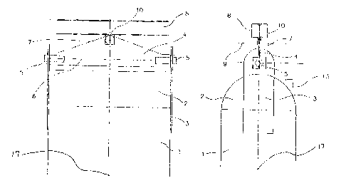
The invention relates to a heat exchanger having at least one heat exchanger block (1) and an insulating vessel which surrounds the heat exchanger, in which securing means (3, 4, 5, 7) are provided for securing the heat exchanger block (1) suspended in the insulation vessel. According to the invention, the heat exchanger block (1) is arranged movably in the insulation vessel (Figure 1).


French Abstract

La présente invention concerne un échangeur de chaleur muni d'au moins un bloc d'échangeur de chaleur (1) et d'un récipient isolant entourant ledit échangeur de chaleur, et dans lequel des dispositifs de fixation (3, 4, 5, 7) sont prévus pour fixer le bloc d'échangeur de chaleur (1) suspendu dans le récipient isolant. Conformément à l'invention, le bloc d'échangeur de chaleur (1) est placé de façon à pouvoir se déplacer dans le récipient isolant (Figure 1).

Claims

Note: Claims are shown in the official language in which they were submitted.


7
Claims
1. A heat exchanger, having at least one heat exchanger
block and an insulating vessel which surrounds the heat
exchanger block, in which securing means are provided for
securing the heat exchanger block hanging in the insulating
vessel, said securing means being characterized in that the
heat exchanger block is arranged movably in the insulating
vessel, and wherein the securing means comprise
a first element, which is fixedly connected to the heat
exchanger block, and
a second element, which is articulately connected to the
first element and said second element being articulately
secured in the insulating vessel, and
wherein the first element comprises two plates secured to
two opposite sides of said heat exchanger block and
second element is a triangular plate.
2. The heat exchanger according to Claim 1, wherein the heat
exchanger block has a lower end and said lower end can move in
at least two spatial directions.
3. The heat exchanger according to Claim 1 or 2,
characterized in that the heat exchanger block is suspended in
such a manner that it can move freely above its centre of
gravity.
4. The heat exchanger according to one of Claims 1 to 3,
characterized in that the heat exchanger comprises at least
two, preferably at least three heat exchanger blocks.
5. The heat exchanger according to Claim 4, characterized in
that the heat exchanger blocks have feed and/or discharge
lines which lead into a common connection line.

8
6. The heat exchanger according to one of Claims 1 to 5,
characterized in that the securing means have joints.
7. The heat exchanger according to Claim 6, characterized in
that the securing means have two axes of rotation which lie
perpendicular to one another.
8. The heat exchanger according to claim 1, wherein said heat
exchanger comprises ten heat exchanger blocks arranged in two
rows of five blocks each.
9. The heat exchanger according to claim 1, wherein said heat
exchanger comprises eight heat exchanger blocks arranged in
two rows of four blocks each.
10. A heat exchanger comprising at least one heat exchanger
block having an upper end and a lower end, an insulating
vessel which surrounds said at least one heat exchanger block,
pipes connected to the upper end and pipes connected to the
lower end of said heat exchanger block for transporting fluids
to and from said heat exchanger block, a first support plate
attached to said heat exchanger block at a first side of said
upper end of said heat exchanger block, a second support plate
attached to said heat exchanger block at a side opposite said
first of said upper end of said heat exchanger block, and a
third support plate attached to a support within said
insulating box,
wherein said first and second support plates are
pivotally attached to said third support plate whereby said
lower end of said heat exchanger block is free to pivot about
an axis passing through the plane of said third support plate,
and said third support plate is attached to said support by a
joint which permits said third support plate and said heat
exchanger block to pivot about an axis perpendicular to the
plane of said third support plate.

9
11. A heat exchanger according to claim 10, wherein said third
support plate is a triangular plate.
12. A heat exchanger according to claim 10 or 11, wherein said
heat exchanger comprises at least two heat exchanger blocks.
13. A heat exchanger according to claim 12, comprising at
least four heat exchanger blocks.
14. A low-temperature air fractionation plant comprising a
principal heat exchanger and at least one fractionation
column, said principal heat exchanger comprising:
at least one heat exchanger block, an insulating vessel
which surrounds the heat exchanger block, pipes connected to
said heat exchanger block for transporting fluids to and from
said heat exchanger block, and securing means for securing the
heat exchanger block hanging in the insulating vessel, wherein
said means for securing said heat exchanger block permit
thermally produced changes in the lengths of said pipes
connected to said heat exchanger block to be compensated for
by movement of said heat exchanger block.
15. An air fractionation plant according to claim 14, wherein
said heat exchanger block has a lower end and wherein the
lower end of the heat exchanger block (1) can move in at least
two spatial directions.
16. An air fractionation plant according to claim 15, wherein
the heat exchanger block (1) is suspended in such a manner
that it can move freely above its center of gravity.

10
17. An air fractionation plant according to claim 14, wherein
the heat exchanger block (1) is suspended in such a manner
that it can move freely above its center of gravity.
18. An air fractionation plant according to claim 14, wherein
the heat exchanger comprises at least two heat exchanger
blocks (1).
19. An air fractionation plant according to claim 18,
comprising at least three heat exchanger blocks.
20. An air fractionation plant according to claim 18, wherein
said pipes connected to said heat exchange block comprise feed
and/or discharge lines which lead into a common connection
line.
21. An air fractionation plant according to claim 14, wherein
the securing means have joints (5,7).
22. An air fractionation plant according to claim 21, wherein
the securing means have two axes of rotation (8,12) which lie
perpendicular to one another.
23. An air fractionation plant according to claim 14, wherein
the securing means have a first element (3), which is fixedly
connected to the heat exchanger block (1), and a second
element (4), which is articulately connected to the first
element (3), the second element (4) being articulately secured
in the insulating vessel.
24. An air fractionation plant according to claim 14, wherein
said heat exchanger comprises ten heat exchanger blocks
arranged in two rows of five blocks each.

11
25. An air fractionation plant according to claim 14, wherein
said heat exchanger comprises eight heat exchanger blocks
arranged in two rows of four blocks each.
26. The heat exchanger of any one of claims 1 to 9 or 13 in
which the triangular plate is articulately secured at its apex
in the insulating vessel.
27. The air fractionation plant of claim 23 wherein the first
element comprises two plates secured to two opposite sides of
said heat exchanger block and said second element is a
triangular plate.
28. The air fractionation plant of claim 27 wherein the
triangular plate is articulately secured at its apex in the
insulating vessel.

Description

Note: Descriptions are shown in the official language in which they were submitted.


CA 02375794 2002-03-06
Description
Heat exchanger
The invention relates to a heat exchanger, having at
least one heat exchanger block and an insulating vessel
which surrounds the heat exchanger, in which securing
means are provided for securing the heat exchanger
block hanging in the insulating vessel, and to its use
in a low-temperature air fractionation plant.
During the low-temperature fractionation of air, the
charge air which is to be fractionated has to be cooled
to the process temperature. This usually takes place
through indirect heat exchange between the charge air
and the product streams obtained in the air
fractionation plant. In plants in which large
quantities of air are processed, the principal heating
exchanger is produced by a plurality of heat exchanger
blocks connected in parallel. The individual heat
exchanger blocks are in this case generally designed as
plate-type heat exchangers.
The thermal insulation of the principal heat exchanger
is provided by introducing the heat exchanger into a
thermally insulated insulating vessel, known as a
coldbox. Various methods are known for securing the
heat exchanger or the individual heat exchanger blocks
in the insulating vessel.
Firstly, it is known to place the heat exchanger blocks
on uprights or supports on the floor or foundation of
the insulating housing. In some cases, profiled
sections are also fitted to two opposite sides of the
heat exchanger block, and these profiled sections are
then laid on top of supports which run transversely
through the insulating space and hold the heat
exchanger block. It is also possible to fit tie-rods on

CA 02375794 2002-03-06
- 2 -
laterally arranged profiled sections, with the aid of
which rods the heat exchanger is suspended from ceiling
supports.of the insulating space..
Furthermore, WO 99/11990 describes holding the heat
exchanger block at the warm end, i.e. in the upper
region, by means of supporting brackets and clamping it
at an angle in the insulating space at the cold end by
means of elements in rope form.
A factor which all these securing methods have in
common is that the heat exchanger block is secured
rigidly in the insulating space. However, when the
plant is started up or in the event of load changes,
the pipelines which are connected to the heat exchanger
block undergo considerable changes in length, of up to
4 mm per metre of pipe length, for temperature reasons.
In order, for example, during cooling to avoid cracks
or other damage to the heat exchanger block or the
pipelines caused by pipe shrinkage, therefore, it has
hitherto been necessary to provide line loops as
shrinkage compensation or to reinforce, at high cost,
the connection pieces on the heat exchanger block. As a
result, the pipe length required for piping increases,
the space taken up by the piping rises and the piping
becomes more complicated.
Therefore, it is an object of the present invention to
develop a heat exchanger which is secured in the
insulating vessel in such a way that the piping becomes
as simple as possible and the line loops for shrinkage
compensation are avoided or at least minimized.
According to the invention, this object is achieved by
a heat exchanger of the type described in the
introduction in which the heat exchanger block is
arranged movably in the insulating vessel.

CA 02375794 2002-03-06
3 -
According to the invention, the heat exchanger block is
secured in such a way that thermally produced changes
in the pipelines connected to the heat exchanger block
are compensated for by a change in position of the
block. For example, when the plant is cooling, the heat
exchanger block is moved with the contracting
pipelines.
It is preferable for the heat exchanger block to be
secured in the insulating vessel in such a way that its
lower end can move in at least two spatial directions.
It is particularly preferred for the heat exchanger
block to be suspended in such a manner that it can move
freely above its centre of gravity.
It is usual for the warm charge air to be supplied to
the upper end of the heat exchanger block and the cold
product gases to be supplied to the lower end of the
heat exchanger block. Accordingly, during start-up or
in the event of load changes, only the pipelines which
are connected to the lower, cold end of the heat
exchanger block undergo significant changes in length,
since the temperature changes at the warm end are only
minor. The fact that the heating exchanger block is
suspended above its centre of gravity means.that it can
be moved relatively easily at its lower end. Therefore,
only low forces act on the pipelines which are
connected to the lower end and, through their
contraction, cause the movement of the heat exchanger
block. Unacceptably high stresses on the pipelines are
avoided.
The invention has proven particularly useful in a heat
exchanger which comprises at least two, preferably at
least four heat exchanger blocks. The invention is
particularly suitable for heat exchangers which
comprise eight or ten heat exchanger blocks in two rows
of in each case four or five blocks. Relatively large
heat exchangers, which comprise a plurality of heat

i
CA 02375794 2002-03-06
4 -
exchanger blocks, require complex piping in order to
distribute the charge air which is to be cooled and the
product streams which are guided in countercurrent to
the individual heat exchanger blocks.
S
The line loops which have hitherto been required as
contraction lengths also make piping more difficult
and, in particular, increase the space which it
requires. Consequently, it is also necessary to provide
larger insulating vessels, which leads to further
increases in the costs of a plant of this type.
The inventive way of securing the heat exchanger blocks
simplifies piping, reduces the size of the insulating
vessel and therefore leads to a considerable reduction
in costs. This is true in particular if the individual
heat exchanger blocks have feed lines and/or discharge
lines which lead into a common collection line.
It is preferable to provide securing means which have
joints, so that the heat exchanger block can be moved
about the joint axes. An articulated suspension of this
type can be achieved with relatively little technical
outlay and has proven particularly successful in
practice.
The invention and further details of the invention are
explained in more detail below with reference to
exemplary embodiments illustrated in the drawings, in
which:
Figure 1 diagrammatically depicts the suspension of a
heat exchanger according to the invention,
and
Figure 2 shows a side view of Figure 1.

CA 02375794 2002-03-06
-4a-
Fig. 3 illustrates a coldbox, indicated with reference
number 11, with two heat exchanger blocks (1) hanging on a
double-T support (8) which is fixed within the coldbox (11).
Fig. 4 is a top view of a coldbox (11) enclosing six
heat exchanger block (1) which are hanging on three double-T
supports (8). The figure shows a discharge pipeline
connected to the cold end of each heat exchanger block (I)
with all discharge pipelines leading to one common
connection line (reference number 12).
Fig. 5 illustrates a heat exchanger block (1) which is
directly fixed to the coldbox (II) without using a double-T
support (8).
Figures 1 and 2 show the upper end of a heat exchanger
block 1, which is used in the principal heat exchanger

CA 02375794 2009-11-12
- 5 -
of a low-temperature air fractionation plant. The principal heat
exchanger as a whole comprises a plurality of heat exchanger
blocks 1 of this type connected in parallel.
The heat exchanger block 1 is up t 240 cm wide. A
connector/distributor 2, known as a header, is arranged on the
heat exchanger block 1, from which header one or more pipelines
(not shown) lead away.
Aluminium plates 3, which project upwards beyond the header 2,
are secured to the heat exchanger block 1 on two opposite sides.
A substantially triangular steel plate 4 or a steel support which
is designed according to static demands is arranged perpendicular
to the aluminium plates 3, above the header 2, and is
articulately connected to the two aluminium plates 3 at two
corners by means of bolts 5. The steel plate 4 can move relative
to the heat exchanger block 1 about the axis 6 formed by the
extension of the two bolts 5.
At the third corner or apex of the steel plate 4 there is a
further joint 7. The steel plate 4 is suspended by means of the
joint 7 from a double-T support 8, which is secured in the
coldbox (not shown) and supports the heat exchanger block 1. The
joint 7 allows movement in the plane of the steel plate 4 or
about an axis 9 perpendicular to the steel plate 4.
Therefore, the heat exchanger block 1 is articulately suspended
in such a manner that it can rotate about two axes 6, 9 which are
perpendicular to one another. The arrangement of the two
aluminium plates 3 and of the steel plate 4 is selected in such a
way that the suspension point 10 is situated vertically above the
centre of gravity of the heat exchanger block 1.
In addition, a horizontal movement of the heat exchanger block 1
can be absorbed by means of a

I, i
CA 02375794 2002-03-06
suitably selected distance between the aluminium plates
3 and the steel plate 4.
The joint 7 is arranged in such a way that the axis 9
is matched to the project-specific requirements, i.e.
to the pipe stresses which occur or can be calculated
for a specific design of the heat exchanger.
One or more pipelines (not shown) for supplying and
discharging the fluid streams which are to be brought
into heat exchange with one another are arranged at the
lower end of the heat exchanger block 1. In the event
of load changes and when the plant is being heated and
cooled down, these pipelines undergo changes in length
of approximately 3 to 4 mm per metre of pipeline
length, for thermal reasons. The fact that, according
to the invention, the heat exchanger block 1 is
suspended above its centre of gravity means that it is
moved by even relatively minor forces acting on its
lower end. The movement of the heat exchanger block 1
compensates for the thermally induced changes in pipe
length, so that there is no need for pipe loops for
compensating for contraction in the pipelines.

Representative Drawing
A single figure which represents the drawing illustrating the invention.
Administrative Status

2024-08-01:As part of the Next Generation Patents (NGP) transition, the Canadian Patents Database (CPD) now contains a more detailed Event History, which replicates the Event Log of our new back-office solution.

Please note that "Inactive:" events refers to events no longer in use in our new back-office solution.

For a clearer understanding of the status of the application/patent presented on this page, the site Disclaimer , as well as the definitions for Patent , Event History , Maintenance Fee  and Payment History  should be consulted.

Event History

Description Date
Time Limit for Reversal Expired 2014-03-06
Letter Sent 2013-03-06
Grant by Issuance 2012-07-03
Inactive: Cover page published 2012-07-02
Inactive: Final fee received 2012-04-04
Pre-grant 2012-04-04
Notice of Allowance is Issued 2011-10-05
Letter Sent 2011-10-05
Notice of Allowance is Issued 2011-10-05
Inactive: Approved for allowance (AFA) 2011-09-19
Amendment Received - Voluntary Amendment 2011-05-19
Inactive: S.30(2) Rules - Examiner requisition 2011-02-25
Amendment Received - Voluntary Amendment 2010-10-04
Inactive: S.30(2) Rules - Examiner requisition 2010-04-15
Amendment Received - Voluntary Amendment 2009-11-12
Amendment Received - Voluntary Amendment 2009-10-05
Inactive: S.30(2) Rules - Examiner requisition 2009-04-03
Inactive: Correspondence - Transfer 2008-09-08
Letter Sent 2007-03-07
Request for Examination Requirements Determined Compliant 2007-02-06
All Requirements for Examination Determined Compliant 2007-02-06
Request for Examination Received 2007-02-06
Inactive: IPC from MCD 2006-03-12
Inactive: Delete abandonment 2003-07-21
Letter Sent 2003-07-16
Inactive: Abandoned - No reply to Office letter 2003-06-10
Inactive: Single transfer 2003-06-05
Application Published (Open to Public Inspection) 2002-09-06
Inactive: Cover page published 2002-09-05
Inactive: First IPC assigned 2002-06-17
Inactive: Courtesy letter - Evidence 2002-04-16
Inactive: Filing certificate - No RFE (English) 2002-04-11
Application Received - Regular National 2002-04-11

Abandonment History

There is no abandonment history.

Maintenance Fee

The last payment was received on 2012-02-27

Note : If the full payment has not been received on or before the date indicated, a further fee may be required which may be one of the following

  • the reinstatement fee;
  • the late payment fee; or
  • additional fee to reverse deemed expiry.

Patent fees are adjusted on the 1st of January every year. The amounts above are the current amounts if received by December 31 of the current year.
Please refer to the CIPO Patent Fees web page to see all current fee amounts.

Owners on Record

Note: Records showing the ownership history in alphabetical order.

Current Owners on Record
LINDE AKTIENGESELLSCHAFT
Past Owners on Record
STEFAN WILHELM
WOLFGANG BADER
Past Owners that do not appear in the "Owners on Record" listing will appear in other documentation within the application.
Documents

To view selected files, please enter reCAPTCHA code :


To view images, click a link in the Document Description column. To download the documents, select one or more checkboxes in the first column and then click the "Download Selected in PDF format (Zip Archive)" or the "Download Selected as Single PDF" button.

List of published and non-published patent-specific documents on the CPD .

If you have any difficulty accessing content, you can call the Client Service Centre at 1-866-997-1936 or send them an e-mail at CIPO Client Service Centre.


Document
Description 
Date
(yyyy-mm-dd) 
Number of pages   Size of Image (KB) 
Representative drawing 2002-06-18 1 12
Description 2002-03-05 7 280
Abstract 2002-03-05 1 13
Claims 2002-03-05 2 51
Drawings 2002-03-05 4 51
Claims 2009-10-04 3 87
Drawings 2009-10-04 4 45
Description 2009-11-11 7 272
Claims 2009-11-11 5 162
Claims 2010-10-03 5 158
Claims 2011-05-18 5 162
Representative drawing 2012-06-05 1 8
Filing Certificate (English) 2002-04-10 1 164
Request for evidence or missing transfer 2003-03-09 1 105
Courtesy - Certificate of registration (related document(s)) 2003-07-15 1 105
Reminder of maintenance fee due 2003-11-09 1 106
Reminder - Request for Examination 2006-11-06 1 118
Acknowledgement of Request for Examination 2007-03-06 1 176
Commissioner's Notice - Application Found Allowable 2011-10-04 1 163
Maintenance Fee Notice 2013-04-16 1 171
Correspondence 2002-04-10 1 23
Fees 2004-03-02 1 31
Fees 2005-02-15 1 29
Fees 2006-01-26 1 31
Fees 2007-02-12 1 28
Fees 2008-03-03 1 28
Fees 2009-02-25 1 46
Fees 2010-02-21 1 28
Fees 2011-02-21 1 34
Fees 2012-02-26 1 34
Correspondence 2012-04-03 1 36