Note: Descriptions are shown in the official language in which they were submitted.
CA 02375881 2001-11-29
WO 01/91618 PCT/US00/15209
ROASTER OVEN WITH HINGED COVER
Background of the Invention
The present invention relates to food preparation containers having a main
body and a
cover, and more particularly to roaster oven having a hinge assembly
connecting the cover to the
main body, the hinge assembly includes a convection fan for converting the
roaster oven into a
convection oven.' The hinge assembly supports the cover in any desired open
position on the
main body of the oven.
Roaster ovens used fox preparing and cooking food are well known in the art.
The
conventional roaster oven includes a main body and a cover that fits on the
main body of the
oven. The main body typically includes a cookwell pan inserted within an outer
shell of the
roaster oven body. Handles are attached to the outer shell of the main body
for ease in carrying
the roaster oven. The cover is closed and rests on an upper edge of the
cookwell pan during
cooking, and to keep the food warm before serving. The cover is removed from
the roaster oven
during the serving of food and during cleaning.
A problem exists with having a separate removable cover. After the cover is
removed
from the roaster oven, it must be placed on a counter top, table, or other
supporting surface. The
cover is usually still hot and includes condensation and other food matter on
its inner surface.
Setting a hot, dirty cover on a counter top or table is not desirable. Hot
liquid dripping from the
inner surface of the cover onto the counter top or table could possibly damage
or at the very least
stain the supporting surface.
Therefore, it would be desirable if the cover of a roaster oven could be
opened without
having to remove the cover from the main body of the oven. In addition, it
would be further
desirable if the cover could be secured in an open position on the main body
of the roaster oven
-1-
SUBSTITUTE SHEET (RULE 26)
CA 02375881 2001-11-29
WO 01/91618 PCT/US00/15209
such that any condensation or other food matter on the inner surface of the
cover drips back into
the cookwell pan of the roaster oven.
Summary of the Invention
The present invention provides a hinge assembly attached to the cover of a
roaster oven.
The hinge assembly is designed so that the cover may be easily opened for
serving food and
removed from the roaster oven for cleaning. The hinge assembly also includes a
convection fan
assembly so that the roaster oven may transformed into a convection oven. The
roaster oven of
the present invention provides the option of~ five different cooking methods,
including normal
cooking, convection cooking, baking, roasting, and steaming. The hinge
assembly also supports
the cover in an open position. With the cover in an open position, the hinge
assembly positions
the cover over the roaster oven to ensure that condensation and other food
matter on the inner
surface of the cover drips back into the roaster oven.
The present invention includes a two-piece container, such as a roaster oven,
having a
main body, a cover, and a hinge assembly connecting the cover to the main
body. The main
body includes a bottom portion with sidewalls extending upwardly therefrom to
create an open
cavity for a cookwell pan to be inserted therein. The sidewalls include
handles located at
opposite ends of the main body to facilitate carrying the roaster oven. The
cookwell pan
includes sidewalls with an upper edge and a flange extending around the
periphery of the
sidewalls. A control panel is located on the front of the roaster oven with at
least one control
knob for controlling cooking operation of the roaster oven, and a status
indicator lamp for
indicating the power status (off or on) of the oven.
The components of the main body include the cover, a cookwell pan inserted
within'a
heatwell pan for heating the cookwell pan. The heatwell pan is surrounded by a
heating element
-2-
SUBSTITUTE SHEET (RULE 26)
CA 02375881 2001-11-29
WO 01/91618 PCT/US00/15209
and an insulating member 66. The heatwell pan is fastened to a collar attached
around the upper
rim of an outer member. The insulating member retains cooking heat in the
heatwell pan and
provides an air space between the heatwell pan and the outer member to allow
for convection
cooling of the outer member during operation of the oven.
A hinge and counterbalance assembly connected between the cover and the outer
member
is used to support the cover in an open position, and to provides for
convection cooking. The
hinge and counterbalance assembly includes a first portion providing the hinge
assembly and the
convection oven function, and a second portion providing the counterbalance.
The first portion
includes a hinge cover, a motor with a motor cooling fan, a convection fan,
and a switch for
controlling operation of the motor and convection fan. .
The hinge assembly includes an upper bracket, a hinge pin acting as the pivot
point
between the first portion and the second portion, a cam mounted on one end of
the hinge pin, a
torsion bar having a cam follower attached to one end thereof, and a lower
bracket in pivoting
relationship with the upper bracket. The cam mounted on one end of the hinge
pin interacts with
the cam follower attached to the torsion bar to allow opening and closing of
the cover. The
torsion bar pressure supports the cover in an open position. The cover may be
opened by lifting
or rotating the cover about the hinge pin. In a secured open position,
condensation and other
matter on the inner surface of the cover drips back into the cookwell pan of
the roaster oven, and
not onto a counter top or table.
Various other features, objects, and advantages of the invention will be made
apparent to
those skilled in the art from the following drawings and detailed description
of the invention. .
-3-
SUBSTITUTE SHEET (RULE 26)
CA 02375881 2001-11-29
WO 01/91618 PCT/US00/15209
Brief Descriution of the Drawings
The drawings illustrate the best mode presently contemplated of carrying out
the
invention.
In the drawings:
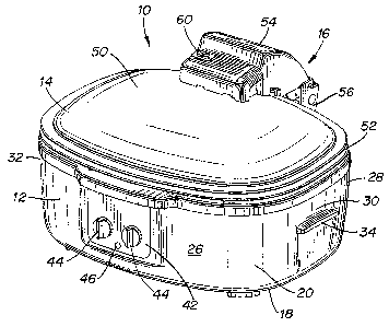
FIG. 1 is a perspective view of a roaster oven with a hinged cover constructed
in
accordance with a preferred embodiment of the present invention;
FIG. 2 is a perspective view of the roaster oven of FIG. l, shown with the
hinged cover in
an open position;
FIG. 3 is an exploded perspective view of the roaster oven of FIG. l;
FIG. 3A is an exploded perspective view of a hinge and counterbalance assembly
connecting the cover to the main body of the oven;
FIG. 4 is a fragmentary side view of the roaster oven with the hinge and
counterbalance
assembly partially broken away and the cover in a closed position;
FIG. 5 is a fragmentary side view of the roaster oven with the hinge and
counterbalance
assembly partially broken away and the cover in a partially open position; and
FIG. 6 is a fragmentary side view of the roaster oven with the hinge and
counterbalance
assembly partially broken away and the cover in a fully open position.
Detailed Description of the Invention
Referring first to FIGS. land 2, a container 10 for preparing or cooking food,
such as a
roaster oven is shown. The container 10 includes a main body 12 and a cover 14
attached to the
main body 12 with a hinge and counterbalance assembly 16. The main body 12
includes a
bottom portion 18 with sidewalls 20 extending upwardly therefrom to create an
open cavity 22
for a cookwell pan 24 to be inserted within the main body 12 of the container
10. The main body
-4-
SUBSTITUTE SHEET (RULE 26)
CA 02375881 2001-11-29
WO 01/91618 PCT/US00/15209
12 of the container 10 is preferably rectangularly shaped with front and rear
opposed sidewalls
26, 28 comprising the front and rear of the container 10, and two opposed end
sidewalls 30, 32,
which are generally shorter in length than front and rear sidewalls 26, 28.
The main body 12 of
the container 10 may also be oval-shaped, round, or square. Each of the end
sidewalls 30, 32 has
a handle 34 attached thereto for carrying the container 10. The cookwell pan
24 includes
sidewalls 36 with an upper edge 38 and a flange 40 extending around the
periphery of the
sidewalls 36.
Located on the front sidewall 26 of the main body 12 is a control panel 42
with at least
one control knob 44 for controlling cooking operation of the roaster oven, and
a status indicator
lamp 46 for indicating the power status (off or on) of the oven. Housed within
the control panel
42 is an automatic timer and a thermostat for adjustable cooking times and
temperatures. The
control knobs 44 provide the option of five different cooking methods,
including normal
cooking, convection cooking, baking, roasting, or steaming.
The cover 14 includes an inner surface 48 and an outer surface 50, with a
flange 52
extending around its periphery. The flange 52 rests on the upper edge 38 of
the cookwell pan
sidewalls 36 when the cover 14 is in a closed position, as shown in Figs. 1
and 4.
Attached to the rear of the cover 14 is a hinge and counterbalance assembly
16. The
hinge and counterbalance assembly 16 includes a first portion 54 attached to
the outer surface 50
of the cover 14, and a second portion 56 extending downwardly from the first
portion 54 and
attached to the rear sidewall 28 of the main body 12. The hinge and
counterbalance assembly 16
is preferably attached to the cover 14 and rear sidewall 28 by rivets, screws,
or bolts and the like.
Alternatively, the hinge and counterbalance assembly 16 may be welded to the
cover 14 and rear
sidewall 28.
-5-
SUBSTITUTE SHEET (RULE 26)
CA 02375881 2001-11-29
WO 01/91618 PCT/US00/15209
Fig. 2 illustrates the container 10 of the present invention with the cover 14
in an open
position. The cover 14 is most typically opened by rotating the cover 14 about
the hinge and
counterbalance assembly 16 at the rear of the cover 14. The first portion 54
of the hinge and
counterbalance assembly 16 includes a convection fan assembly 58 extending
through the cover
14 so that the roaster oven may be operated as a convection oven as well. A
switch 60,
preferably a power switch, located on the first portion 54 of the hinge and
counterbalance
assembly 16 controls operation of the convection fan assembly 58.
Fig. 3 shows an exploded view of the roaster oven container 10 illustrating
its various
components. The first portion 54 of the hinge and counterbalance assembly 16
is attached to the
outer surface 50 of the cover 14. The cover 14 is preferably made of
transparent glass or plastic
to allow for viewing of food items during the cooking process. The main body
12 of the
container 10 includes the cookwell pan 24 for holding food items to be cooked
is inserted within
a heatwell pan 62 for heating the cookwell pan 24. The heatwell pan 62 is in
thermal contact
with the cookwell pan 24 to transfer heat from the heatwell pan 62 to the
cookwell pan 24. The
heatwell pan 62 is surrounded by a heating element 64, and an insulating
member 66. The
heatwell pan 62 is fastened to a collar 70 attached around the upper rim of an
outer member 68.
Fasteners 74 extend through apertures 76 in the collar 70 and heatwell pan 62
to attach the
container 10 together. The outer member 68 is preferably made of a plastic
material. The
insulating member 66 surrounding the heating element 64 is positioned within
the outer member
68. The insulating member 66 retains cooking heat in the heatwell pan 62 and
provides an air
space between the heatwell pan 62 and the outer member 68 to allow for
convection cooling of
the outer member 68 during operation of the roaster oven. Thus, the outer
member 68 is always
-6-
SUBSTITUTE SHEET (RULE 26)
CA 02375881 2001-11-29
WO 01/91618 PCT/US00/15209
cool enough to the touch during operation of the roaster oven. The insulating
member 66 is
preferably made of a fiberglass material with an aluminum foil backing.
The heating element 64 contains heating wires 72 extending therethrough and
coupled to
the control panel 42 for controlling operation of the heating element. The
second portion 56 of
the hinge and counterbalance assembly 16 attaches to the rear sidewall 28 of
the outer member
68. The heatwell pan 62 further includes a temperature sensor 78 attached
thereto and coupled to
the thermostat to control the temperature of the heatwell pan 62.
Fig. 3A is an exploded view illustrating the components of the hinge and
counterbalance
assembly 16. The hinge and counterbalance assembly 16 is used to support the
cover 14 in an
open position, and provides the convection oven function. As mentioned
previously, the hinge
and counterbalance assembly 16 includes a first portion 54 providing the
convection oven
function and a second portion 56 providing the counterbalance function. The
first portion 54
includes a hinge cover 80, a switch 60 for controlling operation of the
convection function, a
motor I00 with a motor cooling fan 102 and a convection fan 58.
The first portion further includes components of the hinge assembly. An upper
bracket
108 separates the hinge components from the convection components. A hinge pin
86 acts as the
pivot point between the first portion 54 and the second portion 56. The hinge
pin 86 extends
through holes formed in a lower bracket 110 the upper bracket 108, and a cam
84. A locking
member 82 holds the first portion 54 together. A torsion bar 89 having a lever
arm or cam
follower 88 attached at one end is fastened to apertures in the sides of the
lower bracket 110.
The cam 84 mounted on one end of the hinge pin 86 interacts with the cam
follower 89 attached
to the torsion bar 89. The torsion bar 89 holds or supports the cover 14 in an
open position. In
_7_
SUBSTITUTE SHEET (RULE 26)
CA 02375881 2001-11-29
WO 01/91618 PCT/US00/15209
other words, the torsion bar 89 prevents the cover 14 from falling down. The
cam 84 may be
designed with stops or indentations so that the cover 14 will stay open in pre-
selected positions.
In operation of the hinge mechanism as shown in FIGS. 4-6, one end of the
torsion bar 89
is fixed to the lower bracket 110 by a nut 96 or other fastening device, while
the other end having
the cam follower 88 attached thereto is free to rotate. As the cover 14 is
opened or closed, the
position on the cam 84 at which the cam follower 88 rests varies. Due to the
irregular shape of
the cam 84, the position of the cam follower 88 varies as well. This causes
the torsion bar 89 to
twist and store energy to hold the cover 14 in an open position. By adjusting
the shape of the
cam 84, the amount, of counterbalance force on the cover 14 is adjusted. FIG.
4 is a fragmentary
cross-sectional view illustrating the hinge assembly 16 in a closed position.
FIG. S is a
fragmentary cross-sectional view of the hinge assembly 16 in a partially open
position. In the
partially open position, while opening or closing the cover 14, the center of
gravity of the hinge
assembly 16 changes as the cover 14 is moved, and the cam follower 88 and
torsion bar 89
spring pressure increases, causing a counter balance effect so that the cover
14 does not freely
fall onto the main body 12 of the cooking container 10. And, FIG. 6 is a
fragmentary cross-
sectional view of the hinge assembly 16 in a fully open position. In the fully
open position, the
center of gravity of the hinge assembly 16 is directly over the hinge pin S6,
so very little cam
pressure is needed for the cover 14 to remain open.
While the invention has been described with reference to a preferred
embodiment, those
skilled in the art will appreciate that certain substitutions, alterations and
omissions may be made
without departing from the spirit of the invention. Accordingly, the foregoing
description is
meant to be exemplary only, and should not limit the scope of the invention
set forth in the
following claims.
_g_
SUBSTITUTE SHEET (RULE 26)