Language selection

Search

Patent 2375932 Summary

Third-party information liability

Some of the information on this Web page has been provided by external sources. The Government of Canada is not responsible for the accuracy, reliability or currency of the information supplied by external sources. Users wishing to rely upon this information should consult directly with the source of the information. Content provided by external sources is not subject to official languages, privacy and accessibility requirements.

Claims and Abstract availability

Any discrepancies in the text and image of the Claims and Abstract are due to differing posting times. Text of the Claims and Abstract are posted:

  • At the time the application is open to public inspection;
  • At the time of issue of the patent (grant).
(12) Patent Application: (11) CA 2375932
(54) English Title: METHOD AND APPARATUS FOR RELOCATING COUNTER-TOP APPLIANCES
(54) French Title: PROCEDE ET DISPOSITIF DE DEPLACEMENT D'APPAREIL DE DESSUS DE COMPTOIR
Status: Deemed Abandoned and Beyond the Period of Reinstatement - Pending Response to Notice of Disregarded Communication
Bibliographic Data
(51) International Patent Classification (IPC):
  • A47J 31/46 (2006.01)
  • A47J 31/44 (2006.01)
  • F16M 11/42 (2006.01)
(72) Inventors :
  • GOLDSTON, JOSEPH P. (United States of America)
(73) Owners :
  • JOSEPH P. GOLDSTON
(71) Applicants :
  • JOSEPH P. GOLDSTON (United States of America)
(74) Agent: BARRIGAR INTELLECTUAL PROPERTY LAW
(74) Associate agent:
(45) Issued:
(86) PCT Filing Date: 2000-06-15
(87) Open to Public Inspection: 2001-01-04
Availability of licence: N/A
Dedicated to the Public: N/A
(25) Language of filing: English

Patent Cooperation Treaty (PCT): Yes
(86) PCT Filing Number: PCT/US2000/040212
(87) International Publication Number: US2000040212
(85) National Entry: 2001-12-28

(30) Application Priority Data:
Application No. Country/Territory Date
09/345,184 (United States of America) 1999-06-30

Abstracts

English Abstract


A counter top appliance (101) is placed on a mobile base (103) to allow for
the relocation of the appliance on a counter. The base includes a set of
wheels (113) and a set of bumpers (111). The wheels are used to move the base
by lifting the bumpers off the counter surface. The bumpers are used to
maintain the basis in a stationary position.


French Abstract

La présente invention concerne un appareil de dessus de comptoir (101) placé sur un support mobile (103) permettant audit appareil de se déplacer sur un comptoir. Le support comprend un ensemble de roues (113) et un ensemble d'éléments de blocage (111). Les roues servent à faire se déplacer le support tout en élevant les éléments de blocage par rapport à la surface du comptoir. Les éléments de blocage servent à maintenir le support dans une position stationnaire.

Claims

Note: Claims are shown in the official language in which they were submitted.

WHAT IS CLAIMED IS:
1. A coffee maker base, comprising:
at least two rolling elements coupled to the bottom of said coffee maker base,
on a first end of said
coffee maker base; and
at least one bumper coupled to the bottom of said coffee maker base, at a
second end of said
coffee maker base, to prevent the movement of said coffee maker base.
2. The coffee maker base of Claim 1, wherein the base includes a handle
adjacent to said second end.
3. The coffee maker base of Claim 1, wherein the rolling elements are rubber
wheels.
4. The coffee maker base of Claim 1, wherein the bumper is a rubber pylon.
5. The coffee maker base of Claim 1, wherein the coffee maker base further
comprises a lip portion
around the top of the coffee maker base.
6. The coffee maker base of Claim 1, wherein the top of the coffee maker base
comprises a friction
surface to prevent the slipping of the coffee maker.
7. The coffee maker base of Claim 1, wherein two wheels are positioned on one
end of the coffee
maker base and two rubber pylons are positioned at the second end of the
coffee maker base.
8. The coffee maker base of Claim 2, wherein the angle formed between the
counter top and the
bottom of the coffee maker base when the handle is lifted is provided by the
following formula:
<IMG>
Where:
D1 is the distance between the wheel bottom and the corresponding axle; and
D2 is the distance between the wheel bottom and the edge of the coffee maker
base bottom.
9. The coffee maker base of Claim 8, wherein the maximum tilt angle, .theta.,
is between 15 and 25
degrees.
10. A method of moving a coffee maker having a base that includes at least one
wheel, comprising:
lifting a handle located on a first end of the base;
rolling the coffee maker to a new position on the counter by using wheels on
the bottom of the
base; and
lowering the handle to position the coffee maker in the new position on the
counter.
-4-

Description

Note: Descriptions are shown in the official language in which they were submitted.


CA 02375932 2001-12-28
WO 01/00071 PCT/US00/40212
METHOD AND APPARATUS FOR RELOCATING COUNTER-TOP APPLIANCES
Background of the Invention
Field of the Invention
The present invention relates to the field of appliances. More particularly,
the present invention relates to
improvements to counter top appliances that enable the relocation of the
appliances.
Description of the Related Art
Appliances are used in nearly every room of a modern household. A washing
machine is usually in a laundry
room, a hair dryer is in a bathroom, a dishwasher is in the kitchen. Counter-
top appliances are those appliances that
are generally found on a counter in a kitchen. Examples of counter-top
appliances include a toaster, a coffee maker,
and a blender. The counter-top appliances are generally stored and used on the
same counter area.
The bottom of the counter-top appliance base usually includes cushions or
bumpers. The bumpers are
generally employed to prevent the appliance from moving during operation. The
bumpers are also used to support the
appliance in a stable position, and prevent vibrations from damaging the
counter surface.
Often times, the counter-top appliance is moved from one position on the
counter to another position. Some
of the reasons for moving the counter-top appliance may include filling water
in a coffee maker, cleaning the appliance,
or simply using the appliance at a location on the counter that is different
from the location where the appliance is
stored. Often, a top-loading appliance, i.e., one that receives material to be
processed from an opening at its top
portion, such as a coffee maker, is stored on the counter under the kitchen
cabinets. To load the appliance, it must be
moved away from under the cabinets. When the counter-top appliance is moved,
the appliance is dragged along the
counter or lifted off the counter. The bumpers on the appliance base are not
conducive to relocation. The appliance is
often jarred as it is dragged along the counter. The appliance may be damaged,
such as by the bumpers breaking, in
the processing of moving around the counter because the bumpers are generally
intended to prevent movement.
Therefore, there is a need for an apparatus that allows for an appliance to be
easily moved from one position on the
counter to another.
Summary of the Invention
In accordance with the present invention, there is presented a counter-top
appliance base which enables the
simple relocation of the appliance around a counter. The base includes at
least two rolling elements, such as wheels,
on one end of the base. The opposite end of the base may include conventional
bumpers or another set of lockable
rolling elements.
Brief Descriution of the Drawings
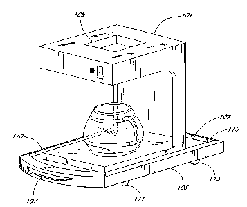
Figure 1 illustrates a top-loading counter top appliance positioned on a base
of the present invention;
Figure 2 is a bottom view of the base of Figure 1; and
Figure 3 is a top view of the base of Figure 1.
-1-

CA 02375932 2001-12-28
WO 01/00071 PCT/US00/40212
Detailed Description of the Preferred Embodiment
The structure and operation of a base of the present invention will now be
disclosed. The structure of the
base will first be described with reference to drawings of a preferred
embodiment of a base. The operation of a base
loaded with a counter top appliance will then be described with reference to
the drawings of the base.
Figure 1 illustrates a base 103 of the present invention that is loaded with a
counter top appliance 101. The
counter top appliance of Figure 1 is a top loading appliance such as for
example, a coffee maker. The appliance
includes a top opening 105 for loading water into the appliance. As may be
appreciated from Figure 1, the loading of
the appliance may be hindered by a cabinet that is located directly above the
appliance because the opening 105 is not
accessible.
The base 103 is loaded with the counter top appliance 101 by placing the
appliance within the recessed top
portion 109 of the base 103 (herein after "base top"). The surface of the base
top 109 is preferably covered by non
slip material such as rubber. In the alternative' the base itself may be
constructed from a material that, in combination
with the textur of the base top 109, prevents the loaded appliance from
slipping. The base additionally includes a lip
portion 110 (herein after "lip") that surrounds the base top 109. The lip 110
operates to prevent the loaded appliance
1 S 101 from slipping off the base top 109.
The bottom of the base (Figure 2) includes a set of rubber stoppers 111
(herein after "stoppers") and a set of
wheels 113. The wheels 113 are preferably made of soft rubber so as to prevent
the jarring of the appliance 101
when it is transported along a counter. The stoppers 111 are used to maintain
the base in position, when it is not
used to relocate the loaded appliance 101. The stoppers 111 are preferably
rubber pylon shaped bumpers that have a
friction coefficient high enough so as to prevent the movement of the base 103
when loaded with an appliance.
The base 103 includes a handle 107 that allows for the relocation of the base.
The handle 107 is attached
to the front of the platform on the stopper end. The handle 107 is used to
lift the bumpers base 103 from the counter
surface. By lifting the stoppers 111 from the counter surface, the base 103
can be maneuvered to another position on
the counter surface. When the stoppers 111 are off the counter surface, the
wheels 113 are allowed to rotate,
thereby enabling the relocation of the base 103.
Figure 2 illustrates a bottom view of the base 103 of Figure 1. The bottom of
the base includes a pair of
grooves 115 for the wheels 113. The grooves 115 are deep enough so as to allow
for the wheels 113 to freely rotate
while secured in the groove by an axle 117. The axle 117 is preferably made
from a rigid material so as to prevent the
wheel 113 from engaging the base 103 when the base is loaded. The grooves may
be formed, for example, by an
injection molding process.
Figure 3 illustrates a top view of the base 103 of Figure 1. The top of the
base includes the base top 109,
the lip 110, and the handle 107. From the view of Figure 3, it can be
appreciated that the lip 110 completely
surrounds the base top 109 so as to prevent the slipping of the loaded
appliance 101 in all directions.
In operation, the appliance 101 is first loaded onto the base top 109. When
the appliance 101 is to be
moved from one position on the counter to another, the user engages the handle
107 to lift the front of the base 103.
-2-

CA 02375932 2001-12-28
WO 01/00071 PCT/US00/40212
The distance that the wheels extend from the base 103, and the location of the
wheels relative to the back of the
base, controls the maximum title of angle for the base when the handle 107 is
raised. At the maximum tilt angle, the
outer edge of the base bottom is in contact with the counter surface. The
outer edge of the base bottom, wheel 113
bottom, and axle 117, form sides of a triangle that defines the maximum tilt
angle. Preferably, the wheel 113 location
and extension are selected in accordance with the equation provided below such
that the maximum angle of tilt is less
than that which causes the appliance to tip off the base top 109. The angle is
provided by the following equation:
Where D, is the distance between the wheel bottom and the corresponding axle,
and
DZ is the distance between the wheel bottom and the edge of the base bottom.
The maximum tilt angle is generally
between 1 and 30 degrees. Preferably, the maximum tilt angle is between 10 and
25 degrees.
The invention is equally applicable to counter-top appliances that are pre-
manufactured with at least one
B = Tan -' ( ~'
2
rolling element, such as a wheel at their bottom. The counter-top appliance
can be manufactured with a handle so as
to allow for the lifting of stoppers or other securing elements and rolling
the appliance on the rolling elements provided.
Although the invention has been described in terms of certain preferred
embodiments, other embodiments
that are apparent to those of ordinary skill in the art, including embodiments
which do not provide all of the features
and advantages set forth herein, are also within the scope of this invention.
Accordingly, the scope of the invention is
intended to be defined by the claims that follow.
-3-

Representative Drawing
A single figure which represents the drawing illustrating the invention.
Administrative Status

2024-08-01:As part of the Next Generation Patents (NGP) transition, the Canadian Patents Database (CPD) now contains a more detailed Event History, which replicates the Event Log of our new back-office solution.

Please note that "Inactive:" events refers to events no longer in use in our new back-office solution.

For a clearer understanding of the status of the application/patent presented on this page, the site Disclaimer , as well as the definitions for Patent , Event History , Maintenance Fee  and Payment History  should be consulted.

Event History

Description Date
Inactive: IPC from MCD 2006-03-12
Application Not Reinstated by Deadline 2004-06-15
Time Limit for Reversal Expired 2004-06-15
Deemed Abandoned - Failure to Respond to Maintenance Fee Notice 2003-06-16
Inactive: Cover page published 2002-06-25
Inactive: Notice - National entry - No RFE 2002-06-18
Inactive: Applicant deleted 2002-06-18
Application Received - PCT 2002-04-11
National Entry Requirements Determined Compliant 2001-12-28
Application Published (Open to Public Inspection) 2001-01-04

Abandonment History

Abandonment Date Reason Reinstatement Date
2003-06-16

Maintenance Fee

The last payment was received on 2002-06-05

Note : If the full payment has not been received on or before the date indicated, a further fee may be required which may be one of the following

  • the reinstatement fee;
  • the late payment fee; or
  • additional fee to reverse deemed expiry.

Patent fees are adjusted on the 1st of January every year. The amounts above are the current amounts if received by December 31 of the current year.
Please refer to the CIPO Patent Fees web page to see all current fee amounts.

Fee History

Fee Type Anniversary Year Due Date Paid Date
Basic national fee - standard 2001-12-28
MF (application, 2nd anniv.) - standard 02 2002-06-17 2002-06-05
Owners on Record

Note: Records showing the ownership history in alphabetical order.

Current Owners on Record
JOSEPH P. GOLDSTON
Past Owners on Record
None
Past Owners that do not appear in the "Owners on Record" listing will appear in other documentation within the application.
Documents

To view selected files, please enter reCAPTCHA code :


To view images, click a link in the Document Description column. To download the documents, select one or more checkboxes in the first column and then click the "Download Selected in PDF format (Zip Archive)" or the "Download Selected as Single PDF" button.

List of published and non-published patent-specific documents on the CPD .

If you have any difficulty accessing content, you can call the Client Service Centre at 1-866-997-1936 or send them an e-mail at CIPO Client Service Centre.


Document
Description 
Date
(yyyy-mm-dd) 
Number of pages   Size of Image (KB) 
Representative drawing 2002-06-19 1 13
Claims 2001-12-27 1 41
Abstract 2001-12-27 1 47
Drawings 2001-12-27 3 39
Description 2001-12-27 3 139
Reminder of maintenance fee due 2002-06-17 1 114
Notice of National Entry 2002-06-17 1 208
Courtesy - Abandonment Letter (Maintenance Fee) 2003-07-13 1 175
PCT 2001-12-27 7 288
Fees 2002-06-04 1 39