Language selection

Search

Patent 2376468 Summary

Third-party information liability

Some of the information on this Web page has been provided by external sources. The Government of Canada is not responsible for the accuracy, reliability or currency of the information supplied by external sources. Users wishing to rely upon this information should consult directly with the source of the information. Content provided by external sources is not subject to official languages, privacy and accessibility requirements.

Claims and Abstract availability

Any discrepancies in the text and image of the Claims and Abstract are due to differing posting times. Text of the Claims and Abstract are posted:

  • At the time the application is open to public inspection;
  • At the time of issue of the patent (grant).
(12) Patent Application: (11) CA 2376468
(54) English Title: IMPACT DROP TESTER FOR PORTABLE CONSUMER PRODUCTS
(54) French Title: TESTEUR DE PRODUITS DE CONSOMMATION PORTABLES AYANT SUBI UN CHOC
Status: Deemed Abandoned and Beyond the Period of Reinstatement - Pending Response to Notice of Disregarded Communication
Bibliographic Data
(51) International Patent Classification (IPC):
  • G01N 03/30 (2006.01)
  • G01N 03/303 (2006.01)
(72) Inventors :
  • SHIM, VICTOR PHYAU WUI (Singapore)
  • LIM, CHWEE TECK (Singapore)
(73) Owners :
  • NATIONAL UNIVERSITY OF SINGAPORE
(71) Applicants :
  • NATIONAL UNIVERSITY OF SINGAPORE (Singapore)
(74) Agent: DIMOCK STRATTON LLP
(74) Associate agent:
(45) Issued:
(86) PCT Filing Date: 2000-06-07
(87) Open to Public Inspection: 2000-12-21
Examination requested: 2001-12-11
Availability of licence: N/A
Dedicated to the Public: N/A
(25) Language of filing: English

Patent Cooperation Treaty (PCT): Yes
(86) PCT Filing Number: PCT/SG2000/000081
(87) International Publication Number: SG2000000081
(85) National Entry: 2001-12-11

(30) Application Priority Data:
Application No. Country/Territory Date
9902933-2 (Singapore) 1999-06-14

Abstracts

English Abstract


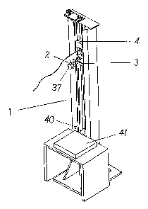
A drop tester (1) including a gripper mechanism (2) for holding a product (37)
to be tested, a guide track, a slider block (3) which is mounted to slide
along the guide track and advance the mechanism toward a target location (41)
and a release device (40) for triggering release of the product from the
mechanism to impact at the target location, characterised in that the gripper
mechanism includes gripper arms (15, 16) coupled to the slider block, the
gripper arms being rotatable relative to the slider block to enable the
orientation of the product to be varied, relative to the target location. The
slider block is preferably releasably coupled to a hoisting block (4) which is
positionable at a predetermined location along the guide track. More
preferably, the gripper arms are pivotally mounted to a housing (23) and
coupled to a piston (22) provided within the housing, the arms pivoting
between a gripping position and a release position upon advancement of the
piston through the housing.


French Abstract

L'invention porte sur un testeur (1) comprenant un mécanisme de préhension (2) servant à retenir un produit (37) à tester, une voie de guidage, un bloc coulissant (3) monté de façon à coulisser le long de la voie de guidage et à faire avancer le mécanisme vers un point cible (41), et un dispositif de dégagement (40) servant à déclencher le dégagement du produit du mécanisme de sorte que le produit retombe sur le point cible. Ce testeur se caractérise en ce que le mécanisme de préhension comporte des bras (156, 16) de préhension couplés au bloc coulissant et pouvant effectuer une rotation par rapport au bloc coulissant afin de pouvoir orienter le produit dans diverses directions par rapport au point cible. Le bloc coulissant est de préférence couplé amovible à une moufle fixe (4) pouvant se positionner à un endroit prédéterminé le long de la voie de guidage. Les bras de préhension sont idéalement montés pivotants sur un corps (23) et couplés à un piston (22) ménagé dans le corps, les bras pivotant entre une position de préhension et une position de dégagement lorsque le piston avance dans le corps.

Claims

Note: Claims are shown in the official language in which they were submitted.


-6-
CLAIMS
1. A drop tester including a gripper mechanism for holding a product to be
tested, a guide
track, a slider block which is mounted to slide along the guide track and
advance the
mechanism toward a target location and a release device for triggering release
of the product
from the mechanism to impact at the target location.
2. A drop tester as claimed in claim 1, characterised by the gripper mechanism
including
gripper arms coupled to the slider block, the gripper arms being rotatable
relative to the slider
block to enable the orientation of the product to be varied, relative to the
target location.
3. A drop tester as claimed in claim 1, characterised by the slider block
being releasably
coupled to a hoisting block which is positionable at a predetermined location
along the guide
track.
4. A drop tester as claimed in claim 3, wherein the blocks are coupled by a
connecting
rod which is releasably held in the hoisting block by a retaining pin which is
arranged to be
retracted to release the slider block from the hoisting block.
5. A drop tester as claimed in claim 2, characterised by the gripper arms
being pivotally
mounted to a housing and coupled to a piston provided within the housing, the
arms pivoting
between a gripping position and a release position upon advancement of the
piston through
the housing.
6. A drop tester as claimed in claim 5, characterised by the housing including
a spring
therewithin and the piston being held against the spring bias in a retracted
condition, when
the arms are in the gripping position.
7. A drop tester as claimed in claim 5, characterised in that the mechanism
includes a
lock to hold the piston in the retracted condition, the lock being released by
the release device.
8. A drop tester as claimed in claim 7, characterised in that the lock is in
the form of a
pivotal arm mounted relative to the housing and adapted to releasably engage a
slot in the
piston.

-7-
9. A drop tester as claimed in any one of claims 5 to 8, wherein the housing
is mounted
to a support provided on the slider block and is adapted to rotate relative to
the support to
effect the rotation of the gripper arms.
10. A drop tester as claimed in claim 9, characterised in that the housing and
support are
provided with respective connection flanges, one of the flanges having arcuate
slots and the
other of the flanges having mounting holes for receipt of fastening bolts
arranged to pass
therethrough, to clamp the flanges together once the housing is rotated to a
desired position.
11. A gripper mechanism for use in the drop tester as claimed in any one of
the preceding
claims characterised in that the mechanism includes gripper arms arranged to
rotate relative
to a support coupling the arms to a slider block of the drop tester.
12. A gripper mechanism as claimed in claim 11, wherein the gripper arms are
pivotally
mounted on a housing and coupled to a piston provided within the housing, the
arms pivoting
between a gripping position and a release position upon advancement of the
piston through
the housing.
13. A gripper mechanism as claimed in claim 12, characterised by the housing
including
a spring therewithin and the piston being held against the spring bias in a
retracted condition,
when the arms are in a gripping position.
14. A gripper mechanism as claimed in claim 13, characterised in that the
mechanism
includes a lock to hold the piston in the retracted condition.
15. A gripper mechanism as claimed in claim 14, characterised in that the lock
is in the
form of a pivotal arm mounted relative to the housing and adapted to
releasably engage a slot
in the piston.
16. A gripper mechanism as claimed in any one of claims 12 to 15, wherein the
housing
is mounted to a support and is adapted to rotate relative to the support to
effect the rotation
of the gripper arms, wherein the housing and support are provided with
respective connection
flanges, one of the flanges having arcuate slots and the other flange having
mounting holes
for receipt of fastening bolts arranged to pass therethrough to clamp the
flanges together, once
the housing is rotated to a desired position.

Description

Note: Descriptions are shown in the official language in which they were submitted.


CA 02376468 2001-12-11
WO 00/77487 PCT/SG00/00081
_1_
IMPACT DROP TESTER FOR PORTABLE CONSUMER PRODUCTS
FIELD OF THE INVENTION
This invention relates to mechanical-shock fragility testing of portable
consumer products
such as portable mobile phones, pagers, etc.
BACKGROUND OF THE INVENTION
To assess physical robustness of portable consumer products, manufacturers
subject these
products to impact and subsequently test their continued function and
reliability. Currently,
many manufacturers conduct such tests by dropping the product by hand.
However, such a
drop test is not suitable for controlled repeatability and therefore poses a
major problem in
verifying test data. To overcome this problem, various drop test devices have
been suggested.
For example, Japanese Patent No. 1-239465 discloses a mechanical device for
elevating a
product and dropping it onto a target surface and U.S. Patent No. 4910995
discloses repeat
drop tests of a compact disc using a string. An impact testing machine is also
disclosed in
U.S. Patent No. 3412598, where a test package is propelled at high velocity
via a horizontal
rail and is disengaged by a quick release mechanism, allowing it to continue
its motion
towards an impact receiving surface. Although the prior art discloses
repeatable drop testing
of products there is no disclosure of a generally versatile mechanism which
allows for the
orientation of the product to be specifically manipulated and controlled for
repeat testing.
OBJECT OF INVENTION
It is a primary obj ect of the invention to facilitate drop testing of a
portable consumer product
at any desired orientation and drop height, to allow assessment of damage to
the product when
it is subjected to impact at different orientations and from various drop
heights.
Other objects, features and advantages of the present invention will become
apparent from the
detailed description which follows, or may be learned by practice of the
invention.

CA 02376468 2001-12-11
WO 00/77487 PCT/SG00/00081
-2-
SUMMARY OF INVENTION
In accordance with the invention, there is provided a drop tester including a
gripper
mechanism for holding a product to be tested, a guide track, a slider block
which is mounted
to slide along the guide track and advance the mechanism toward a target
location and a
release device for triggering release of the product from the mechanism to
impact at the target
location.
Preferably, the gripper mechanism includes gripper arms coupled to the slider
block, the
gripper arms being rotatable relative to the slider block to enable the
orientation of the product
to be varied, relative to the target location.
In another aspect, there is provided a gripper mechanism for use in the above
drop tester.
BRIEF DESCRIPTION OF ACCOMPANYING DRAWINGS
The accompanying drawings which are incorporated into and constitute a part of
the
description of the invention, illustrate embodiments of the invention and
serve to explain the
principles of the invention. It is to be understood, however, that the
drawings are designed
for purposes of illustration only, and not as a definition of the limits of
the invention for
which reference should be made to the claims appearing at the end of the
description.
Figure 1 is an isometric view of an embodiment of a drop tester constructed
according
to the present invention;
Figure 2 is a sectional side view of a quick release mechanism used in the
drop tester;
Figure 3 is a sectional front view of the quick release mechanism;
Figure 4 is an exploded isometric view of a gripper mechanism of the drop
tester;
Figure S is a plan view of the gripper mechanism, with a piston housing
partially
sectioned to expose the piston for the purpose of clarity;
Figure 6 is a sectional view along line A-A in Figure 5;
Figure 7 is an isometric view of the left gripper;

CA 02376468 2001-12-11
WO 00/77487 PCT/SG00/00081
_3_
Figure 8 is an isometric view of the right gripper;
Figure 9 is a plan view of the piston housing and piston housing support;
Figure 10 is a sectional view of the piston housing, taken along line A-A in
Figure 9;
and
Figure 11 is a sectional view of the piston housing support, taken along line
B-B in
Figure 9.
DESCRIPTION OF A PREFERRED EMBODIMENT OF INVENTION
A drop tester 1 is shown in Figure 1 as comprising a gripper mechanism 2,
which is mounted
onto a slider block 3. The slider block 3 is coupled to a hoisting block 4 via
a quick release
connector 5. This hoisting block 4 can be raised to the desired drop height
via the hoisting
cable 6. Both the slider block 3 and hoisting block 4 are adapted to slide
between a vertical
guide track formed by column supports 7. When the coupled hoisting block 4 and
slider
block 3 are raised to the desired drop height, the slider block 3 can be
uncoupled by a quick
release connector 5 which is activated by pulling on the release cable 8.
The quick release connector 5 is shown in more detail in Figures 2 and 3. A
connecting rod
10 is screwed into the slider block 3 and kept in position by a lock nut 9.
The connecting rod
is in turn attached to a quick-release fixture 11 by a retaining pin 10a
resting on a release pin
12. The quick-release fixture 11 is attached to the base of the hoisting block
4 by two screws
13. When the release cable 8 is pulled, the release pin 12 is disengaged from
supporting the
retaining pin 10a, thus releasing the slider block 3. The slider block 3 then
falls freely under
gravity, guided by the two vertical column supports 7.
Referring now to Figures 4 to 8, the gripper mechanism 2 comprises a first
gripper arm 15 and
a second gripper arm 16 pivotally mounted to a respective flange of a piston
housing 23.
Inner ends of the gripper arms 15, 16 are coupled to a piston 22 via a pin and
slot type
engagement such that linear movement cf the piston effects pivotal movement of
the gripper
arms relative to the respective flange, from a gripping position to a release
position for
releasing a product 37. The gripper arm 16 is provided with a gripper jaw 17,
with a rubber
pad 18 affixed to it, and the jaw is adjustable relative to the arm via a
screw thread 19. The

CA 02376468 2001-12-11
WO 00/77487 PCT/SG00/00081
-4-
gripper arm 15 is also formed with a jaw 21, with a rubber pad 20 affixed
thereto.
The piston housing 23 is provided with a piston retainer 24 affixed to it via
screws 25 to
prevent the piston 22 from sliding completely out of the piston housing. The
piston housing
23 is connected to a piston housing support 26 by screws 27. A locking bar
support 28 is also
mounted on the piston housing support 26 via two bolts 29. The locking bar
support 28 is
mounted to a pin 31 and held on the pin 31 by locking pin 32, to allow for
rotation of the
locking bar 30 about the pin 31. The locking bar engages with a slot 39 of the
piston 22 to
releasably hold the piston in a retracted position, against the bias of spring
38. The piston
housing support 26 is itself mounted onto the slider block 3.
Figure 9 shows the piston housing 23 as being provided with connection flange
34 which
connects the housing to the piston housing support 26 via a mating connection
flange 36.
Figure 10 shows the connection flange 34 of the piston housing 23, with two
curved slots 33
machined into it. This allows the piston housing 23 to rotate to any angle
before it is fastened
to the mating connection flange 36 of the piston housing support 26. Fastening
is effected via
bolting through eight of the mounting holes 35 shown in Figure 11. The ability
to rotate the
piston housing 23 means that the gripper arms 15, 16 are also rotatable to any
angle before
the piston housing 23 is fastened to the piston housing support 26, to thereby
allow the test
product 37 to assume a desired orientation at impact.
With reference to Figure 5 again, when the gripper jaws 17, 21 are clamped to
the product 37,
the piston 22 is pushed into the piston housing 23, thus compressing the
helical spring 38.
To retain the piston 22 within the piston housing 23, the locking bar 30 is
pushed into the slot
39 as indicated in Figure 4. The gripper mechanism 2 is then primed, ready to
execute a drop
test.
To conduct the test, the coupled slider block 3 and hoisting block 4 are
raised to the required
drop height, and the release cable 8 connected to the release pin 12 is
pulled. This uncouples
the slider block 3 with its attached gripper mechanism 2, allowing it to fall
freely and slide
between the column supports 7. When the slider block descends to the level of
a stationary
release bar 40, located close to the target impact location/surface 41,
contact between the
release bar 40 and the locking bar 30 pushes the latter into an unlocked
position. This
disengages the spring-loaded piston 22, which fires forwardly to rotate the
grippers 15, 16 and

CA 02376468 2001-12-11
WO 00/77487 PCT/SG00/00081
-5-
release the product 37. The product 37 then continues its motion unrestrained
for a
momentary period before it strikes the target impact surface 41 at the
orientation with which
it was gripped prior to release. The motion of the slider block 3 is arrested
by the shock
absorber 14 shown in Figure 1.
As can be appreciated from the above, many modifications and variations may be
made to the
drop tester without departing from the spirit and scope of the invention, as
described. For
example, the slider block and hoisting block may be connected via any suitable
means such
as electromagnetic coupling, the hoisting block itself may be elevated
mechanically such as
by a motor and the locking bar and release lever may be replaced with any
other appropriate
release device suitable for releasing the gripper arms at a predetermined
location. The
specific form of the gripper arms may also be modified, as desired.

Representative Drawing
A single figure which represents the drawing illustrating the invention.
Administrative Status

2024-08-01:As part of the Next Generation Patents (NGP) transition, the Canadian Patents Database (CPD) now contains a more detailed Event History, which replicates the Event Log of our new back-office solution.

Please note that "Inactive:" events refers to events no longer in use in our new back-office solution.

For a clearer understanding of the status of the application/patent presented on this page, the site Disclaimer , as well as the definitions for Patent , Event History , Maintenance Fee  and Payment History  should be consulted.

Event History

Description Date
Inactive: IPC from MCD 2006-03-12
Application Not Reinstated by Deadline 2004-03-12
Inactive: Dead - No reply to Office letter 2004-03-12
Deemed Abandoned - Failure to Respond to Maintenance Fee Notice 2003-06-09
Inactive: Status info is complete as of Log entry date 2003-04-29
Inactive: Abandoned - No reply to Office letter 2003-03-12
Inactive: Entity size changed 2002-06-07
Inactive: Courtesy letter - Evidence 2002-06-04
Inactive: Cover page published 2002-06-04
Letter Sent 2002-05-29
Inactive: Acknowledgment of national entry - RFE 2002-05-29
Application Received - PCT 2002-04-16
All Requirements for Examination Determined Compliant 2001-12-11
National Entry Requirements Determined Compliant 2001-12-11
Request for Examination Requirements Determined Compliant 2001-12-11
National Entry Requirements Determined Compliant 2001-12-11
Application Published (Open to Public Inspection) 2000-12-21

Abandonment History

Abandonment Date Reason Reinstatement Date
2003-06-09

Maintenance Fee

The last payment was received on 2002-05-24

Note : If the full payment has not been received on or before the date indicated, a further fee may be required which may be one of the following

  • the reinstatement fee;
  • the late payment fee; or
  • additional fee to reverse deemed expiry.

Patent fees are adjusted on the 1st of January every year. The amounts above are the current amounts if received by December 31 of the current year.
Please refer to the CIPO Patent Fees web page to see all current fee amounts.

Fee History

Fee Type Anniversary Year Due Date Paid Date
Request for examination - small 2001-12-11
Basic national fee - small 2001-12-11
MF (application, 2nd anniv.) - standard 02 2002-06-07 2002-05-24
Owners on Record

Note: Records showing the ownership history in alphabetical order.

Current Owners on Record
NATIONAL UNIVERSITY OF SINGAPORE
Past Owners on Record
CHWEE TECK LIM
VICTOR PHYAU WUI SHIM
Past Owners that do not appear in the "Owners on Record" listing will appear in other documentation within the application.
Documents

To view selected files, please enter reCAPTCHA code :


To view images, click a link in the Document Description column (Temporarily unavailable). To download the documents, select one or more checkboxes in the first column and then click the "Download Selected in PDF format (Zip Archive)" or the "Download Selected as Single PDF" button.

List of published and non-published patent-specific documents on the CPD .

If you have any difficulty accessing content, you can call the Client Service Centre at 1-866-997-1936 or send them an e-mail at CIPO Client Service Centre.

({010=All Documents, 020=As Filed, 030=As Open to Public Inspection, 040=At Issuance, 050=Examination, 060=Incoming Correspondence, 070=Miscellaneous, 080=Outgoing Correspondence, 090=Payment})


Document
Description 
Date
(yyyy-mm-dd) 
Number of pages   Size of Image (KB) 
Representative drawing 2002-06-02 1 7
Claims 2001-12-10 2 96
Drawings 2001-12-10 4 98
Abstract 2001-12-10 1 60
Description 2001-12-10 5 224
Acknowledgement of Request for Examination 2002-05-28 1 179
Reminder of maintenance fee due 2002-05-28 1 111
Notice of National Entry 2002-05-28 1 203
Request for evidence or missing transfer 2002-12-11 1 102
Courtesy - Abandonment Letter (Office letter) 2003-04-15 1 167
Courtesy - Abandonment Letter (Maintenance Fee) 2003-07-06 1 175
PCT 2001-12-10 7 302
Correspondence 2002-05-28 1 25
Fees 2002-05-23 1 37