Note: Descriptions are shown in the official language in which they were submitted.
CA 02376514 2001-12-06
WO 00/77576 PCT/IL00/00347
METHOD FOR PRODUCING A DIGITALLY IMAGED SCREEN FOR USE IN A
SCREEN PRINTING PROCESS
FIELD OF THE INVENTION
The present invention relates to screen printing methods, and more
particularly, to
a novel method for the digital production of printing screens using ink jet
printing
technology.
~o
BACKGROUND OF THE INVENTION
One of the most widely used methods of printing uses a screen. The basis of
the
screen is a woven thread with a net-like structure of holes. Early screens
were fabricated
from silk, but partly because of the expense of this material and partly from
the point of
view of performance, silk has been replaced by nylon, polyester or even metal.
The screen
is selectively blocked so that ink will pass through only in areas which are
necessary to
print. Screens come in a variety of mesh openings and thicknesses, depending
on the
particular application. The screen serves as a support for the blocking
material, supporting
zo portions of the blocking material which are unconnected and would otherwise
be
unsupported. For instance, in printing the letter 'O', in order to allow ink
to form the
CA 02376514 2001-12-06
WO 00/77576 PCT/IL00/00347
outside of the letter without filling the center, there must be blocking
material in the center
of the letter. The screen serves to support this center blocking material so
that it cannot
fall out of the stencil. The screen is tensioned on a frame and ink is pressed
onto the
stencil with a squeegee so that it is applied to a substrate placed below the
screen in those
places where it is necessary to print.
The screen printing process is used with inks formulated to adhere to a large
variety of surfaces, and the printing process itself can handle a large
variety of shapes. This
makes screen printing the most versatile of printing processes and it is
widely used to print
on textiles, packaging, china-ware, glass, plastics, wood and metals, printed
circuit boards
to and posters.
In order to make a screen, it is necessary to prepare artwork, then to
photograph it
to produce a positive film that in turn can be used to produce the exposed
pattern on the
photosensitive screen coating. Such original artwork may now be most easily
prepared
using a computer. The digital information in the computer is then used in an
image-setter
t S to produce the positive film. There are a variety of prior art
photographic methods of
producing the stencil.
In the direct method, solutions of light-sensitive coatings are applied
directly onto
the screen, then dried and hardened into a printing pattern by exposure to
ultraviolet (UV)
light through a positive film in which the image areas are opaque to UV light.
After
z« exposure, the unexposed, unhardened coating is washed away allowing ink to
pass
through.
Ofi-08-2001 CA 02376514 2001-12-06 IL0000347
There are other, indirect methods of producing the stencil. The light
sensitive
coating may be prepared as a pre-sensitized film on an intermediate base. The
film can
then either be transferred onto the screen before exposure and development or
after
exposure and development.
There is a growing need in many markets to print low run lengths and print on
demand. This is becat,~se it is expensive to carry large stocks of pre-printed
items and
because there is an increasing demand for product customization to the need of
individual
customers or to relatively small groups of customers instead of mass
production. The
speed and cost of screen production becomes important and any means of
simplifying and
to reducing costs is advantageous. There is also a trend to use computers to
prepare artwork
for printing and it would obviously be more convenient if the screen could be
prepared
directly from the computer information without recourse to the preparation of
an
intermediate photomask.
Inventors have attempted to use inkjet to produce masks on the screen itself,
so
t 5 that the unimaged, unprotected parts of the screen can be flood-cured by
LTV radiation.
An example of this is described in EP 0 492 351 B1 by Gerber Scientific
Products Inc.
The problems of ink receptivity of the screen are acknowledged and the
preferred method
of overcoming these problems is by the introduction of talc. onto the surface
of the screen,
to absorb the ink jetted ink. This absorbs the liquid medium of the~ink, to
give a dried
2o graphic. The graphic is described as preferably formed from a water-soluble
ink.
Subsequently, similar inkjet integral masks have also been used to produce
flexo
plates. WO 97!25206 (Polyfibron) describes such a method. The inks used are
either
AMENDED SHEET
06-08-2001 CA 02376514 2001-12-06 IL0000347
solvent based or "phase change". After deposition, the ink is dried by
evaporation of the
volatile solvent or, in the case of phase change inks, by solidification.
After the ink mask
is used by flood-exposing the plate with UV light, the image areas are washed
out. No
mention is made of any difficulties in removing the dry mask after flood-
exposure, save
to point out that inks are useful so long as they can be removed by subsequent
washing,
without damaging the surface of the plate.
The following later patents recognize the problem of post flood-curing washout
and
try to deal with it. PCT WO 98/51750 (Markem Corporation) describes such a
process.
The inks used are "phase change" - known also as hot-melt inks. The ink dries
by
solidification as it impacts the screen. The patent recognizes the difficulty
of removing
the solid ink after it had served its purpose as a mask and the inks are
formulated to be
auto-dispersible in water.
GB 2 315 076 (Sericol) recognizes the same problem when phase change inks are
used as integral masks for screen printing. Their solution is to use a water-
soluble
15 material having a wax-like texture.
US 5,878,076 (McCue) attempts to circumvent the problem of mask removal after
UV flood-exposure by depositing only the screen itself by, for instance,
inkjet, so that the
deposit is in all areas except those of the image. The deposit is then
subsequently flood
UV-cured from both sides. As a layer of inkjet ink is relatively thin, the
patent provides
2o the possibility of multiple passes to achieve the desired screen thickness.
Therefore, it would be desirable to provide a method for screen printing which
would
not require the production of an intermediate positive film, would allow
screen masters to
3a
AMENDED SHEET
06-08-2001 CA 02376514 2001-12-06
be imaged directly from digitat information in the computer so as to simplify
the known
work flow of the printing process, would provide an easily washable ink for
forming the
mask and would be quicker and more economical to use.
3b
AMENDED SHEET
06-08-2001 CA 02376514 2001-12-06 IL0000347
SUMMARY OF THE INVENTION
Accordingly, it is a broad object of the present invention to overcome the
problems of
the prior art and provide a method of producing a digital screen directly from
digital
information in the computer in an economical fashion. Specifically, the
invention seeks to
overcome the problems of providing optimum ink-screen surface interaction to
produce a
high quality inkjet mask, together with very easy removal of the mask after it
has fulfilled
its masking function and to provide screen formulations that make this
possible.
In accordance with a preferred embodiment of the present invention, there is
provided a method of producing a screen using digital imaging, said method
comprising
the steps of
providing digital image information from a computer system;
providing an image-ready printing blank comprised of a screen coated with a
photosensitive coating that permits aqueous-based inkjet ink to be deposited
evenly on its
surface and remain in liquid condition;
printing said digital image information in UV-blocking aqueous-based inkjet
ink
on said photosensitive coating with an ink jet printer, forming an image
struct~xre having
exposed and unexposed areas of said photosensitive coating;
flood-curing said photosensitive coating having said formed image structure
with
UV light such that said exposed areas of said photosensitive coating are cured
while said
2o unexposed areas of said photosensitive coating are blocked from UV curing
by said
UV-blocking ink; and
4
AMENDED SHEET
06-08-2001 CA 02376514 2001-12-06 ~L~~~~~7
washing said photosensitive coating so that said UV-blocking ink and said
unexposed image structure areas are removed,
such that the remaining cured areas of said photosensitive coating form a mask
on
said screen for use in the screen printing process.
In accordance with another aspect of the invention there is provided a screen
printing blank usable in a screen printing process, said printing blank
comprising:
an image-ready printing blank comprised of a screen coated with a
photosensitive
coating that permits aqueous-based inkjet ink to be deposited evenly on its
surface and
remain in liquid condition.
In a preferred embodiment, a screen is provided with a photosensitive coaxing,
and
a digitally determined image from a computer is printed on the screen by means
of an
inkjet printer. It is preferable to use a flat bed ink jet imaging system so
that the screen
can be stretched in a frame and directly placed under the ink jet head. The
ink used need
not have strong colorant, but functions as a LJV mask and thus must contain a
UV
absorbing pigment. The ink is not absorbed into the photosensitive coating,
but remains
as an undried image on the surface. The ink must remain wet so that that it
does not
spread and therefore gives a sharp image, and so that the W absorbent material
remains
concentrated The screen is then irradiated with UV, and the areas which have
been
printed with ink serve to mask the photosensitive coating from the I1V light,
while those
2o areas having no ink are exposed so that the photosensitive coating is
polymerised by the
UV.
AMENDED SHEET
06-08-2001 CA 02376514 2001-12-06 ~~'~~~~~7
After the UV irradiation stage, the screen is washed so as to remove the ink
and
the unpolymerised photosensitive coating. Any liquid that is suitable for
washing out the
unpolymerised photosensitive coating will also wash away the ink. This leaves
the screen
with only the polymerised areas of the photosensitive coating that create the
blocked areas
through which the ink will not pass.
Thus, the inventive method provides a digitally imaged screen, directly from a
_ digital image in the computer, which can then be used in any conventional
screen printing
process.
Other features and advantages of the invention will become apparent from the
following drawings and descriptions.
6
AMENDED SHEET
CA 02376514 2001-12-06
WO 00/77576 PCT/IL00/00347
BRIEF DESCRIPTION OF THE DRAWINGS
For a better understanding of the invention with regard to the embodiments
thereof, reference is made to the accompanying drawings, in which like
numerals designate
corresponding elements or sections throughout and in which:
Fig. 1 shows a diagramatic representation of a prior art method of the silk-
screen
pnnttng process;
Figs. 2a-c depict cross-sectional views of the stages of the prior art method
of
producing a stencil photographically, previously described as the direct
method;
t o Figs. 3 a-a depict cross-sectional views of the stages of the prior art
method of
producing a stencil photographically, previously described as an indirect
method where
transfer from an intermediate material to the screen is done after imaging and
washing out;
Figs. 4a-d depict cross-sectional views of the stages of the prior art method
of
producing a stencil photographically, previously described as an indirect
method where
transfer from an intermediate material to the screen is done before the
imaging and
washing stages;
Fig. 5 shows a photosensitive screen stencil which has been imaged and washed
out according to one of the above described prior art procedures; and
Figs. 6a-a show cross-sectional views of the steps of the process of producing
a
z~ stencil, in accordance with the method of the present invention.
CA 02376514 2001-12-06
WO 00/77576 PCT/IL00/00347
DETAILED DESCRIPTION OF THE INVENTION
The following description begins with a review of prior art methods, shown in
Figs. 1-5.
To print in the screen printing method, as shown in prior art Fig. 1, stencil
20 may
be used for printing after being tensioned in a metal or wooden frame 22 and
having
substrate 24 placed beneath it. Stencil 20 must be selectively blocked so that
ink 26 can
pass through onto the printing substrate 24 only in the areas which are
necessary to print.
For the simplest type of work, this may be achieved by cutting stencil 20 from
a laminated
film material and then applying it to screen 28. Ink 26 is pressed onto
stencil 20 with
m squeegee 27 so that ink 26 passes through the unblocked areas of screen 28
onto substrate
24, while ink 26 does not pass through the areas of screen 28 which are
blocked by stencil
20.
As mentioned above, the prior art method of producing artwork for silk-screen
printing often requires photographing the material. There are a variety of
photographic
5 methods of producing stencil 20. A prior art method known as the direct
method is shown
diagramatically in prior art Figures 2a-c. These figures show cross-sectional
views of the
strictures of screen printing stencils.
As seen in Fig. 2a, stencil 20 is formed by screen 28 to which solutions of
light
sensitive coatings 30 are applied. Screen 28, represented by cross lines, is
filled with
Zo photosensitive coatings 30, which are then dried. Positive film 32 is laid
on stencil 20.
Positive film 32 is comprised of black, UV-opaque image areas and clear, UV-
transparent
background, or non-image areas, and functions as a UV mask in contact with
stencil 20.
8
06-08-2001 CA 02376514 2001-12-06 ~f~O~~'~7
Positive film 32 is comprised of black, LIV-opaque image areas and clear, LTV-
transparent
background, or non-image areas, and functions as a LTV mask in contact with
stencil 20.
Figure 2b shows the exposure of the combination of film image 32 and stencil
20
to flood LJV Light. Coatings 30 are selectively hardened into a printing
pattern by
exposure to LTV light through positive film 32 in which the image areas are
opaque to the
UV light. UV light penetrates film image 32 in the non-image areas and cures
the
corresponding areas of photosensitive coating 30 creating cured, cross-linked
polymeric
material 34.
Film image 32 is then physically removed and screen 28 is washed with a
solvent,
1 o which may be water. As seen in Fig. 2c, the washing removes the uncured
areas of
photosensitive coating 30 leaving only the open woven mesh of screen 28 in
these areas,
while retaining cross-linked polymeric material 34. Stencil 20 may then be
used for
printing as described in Fig. 1.
There are other, indirect methods of producing the stencil. The light
sensitive
coating may be prepared as a pre-sensitized film on an intermediate base. The
film can
then either be transferred onto the screen before exposure and development or
after
exposure and development.
Prior art Figures 3a-a show cross-sectional views of an indirect method of
transfer
from an intermediate material to the screen after the imaging and washing
stages. Figure
3a shows the donor sheet, characteristically a LJV transparent substrate 36,
comprised of a
material such as polyester, coated with a photosensitive coating 38. A
positive film
serves as photomask 40 and is laid in contact with coating 38. Figure 3b
depicts a t7V
9
AMENDED SHEET
06-08-2001 CA 02376514 2001-12-06 ~L~~~~347
exposure thmugh photomask 40 onto coating 38. Where the UV is not blocked by
photomask 40, coating 38 is hardened by polymerisation. The areas of coating
38 which
were directly under the LTV opaque areas of photomask 40 remain unaffected.
Photomask
40 is then physically removed and the surface of coating 38 is washed, usually
with either
an organic solvent or a weak alkali solution. This solution washes out the
unpolymerised
areas, leaving the polymerised areas of coating 38 as depicted in Figure 3c.
Coating 38 is
then pressed in contact with screen 28 as shown in Figure 3d and either by
means of
pressure, heat or solvent, is transferred to the screen as shown in Figure 3e,
thus providing
areas in which the ink is blocked, for the screen printing process.
Prior art Figures 4a-d describe an indirect transfer process where transfer
from an
intermediate material to the screen is done before the imaging and washing
stages. Figure
4a shows support 42 coated with photosensitive coating 38 being pressed
together with
the screen 28, so as to transfer the photosensitive material to screen 28. As
in Fig. 3, the
transfer may be affected either by heat or pressure or a combination of these,
or by
solvent, possibly combined with heat and pressure. Support 42 is then
physically peeled
away and the resulting screen is shown in Fig. 4b. IJV flood exposure through
photomask 40 is shown in Fig. 4c. This cures the areas which are not blocked
by
photomask 40. After subsequent washing, as previously described, a print-ready
screen
results, as shown in Fig. 4d.
2o Fig. 5 shows a photosensitive screen stencil which has been imaged and
washed
according to one of the above described procedures. The image areas show the
exposed
screen through which ink may pass during printing.
AMENDED SHEET
06-08-2001 CA 02376514 2001-12-06
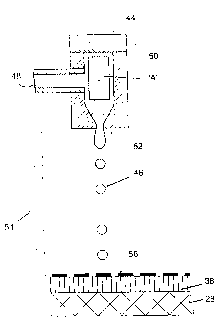
Referring now to Figs. 6a-d, which describe the present invention. Fig. 6a
shows
screen 28 with a photosensitive coating 38 coated within the screen.
Fig. 6b shows an ink jet head 44 jetting aqueous inkjet ink 46 onto the
surface of
photosensitive coating 38 of screen 28. The system shown is, by way of
example, a
generic impulse (drop-on-demand) system, although any type of ink jet system
is usable
in this invention. In this system, ink supply 48 is delivered at atmospheric
pressure.
Piezo-electric crystal 50 produces a pressure wave along arrow "A" upon
actuation by an
electric signal. This pressure wave causes the ejection of a droplet of inkjet
ink 46 from
ink jet nozzle 52. A data pulse train 54 produces a pattern of dots as ink jet
head 44
traverses the surface of screen 28 depositing image 56.
Thus, inkjet ink 46 is deposited in a pattern that is digitally determined to
provide
the information directly from a computer that will be printed by the screen by
a
conventional screen printing process. It is essential to the invention that
inkjet ink 46 is
not absorbed into the photosensitive coating, but remains as an undried image
on the
~ s surface. This has various advantages which will be explained below. It is
also essential
that the surface of photosensitive coating 38 has suitable wetting properties
so that when
ink droplets 46 impact the surface, they provide smooth, even contact without
excessive
spreading and without reticulation.
Figure 6c shows the imaged screen being irradiated with tTV radiation. In this
2o case, inkjet ink 46 forms a barrier to the radiation. Preferably, it
contains carbon black as
the UV absorbing pigment, but dyes or pigments with strong absorption in the
UV region
may also be used. Ink 46 need have very little actual colorant that is evident
to the naked
11
AMENDED SHEET
06-08-2001 I L0000347
CA 02376514 2001-12-06
eye, just a sufficient amount to make it visible for following the imaging
procedure. The
UV absorption function of the dye is more important. As the ink remains wet
and is not
absorbed into photosensitive coating 38 but remains on the surface, the ink
does not
spread into coating 38 and therefore gives a sharp image with concentrated
pigment or
dye or other LTV absorbent material. Where there is no inkjet image 56, the
radiation
polymerizes photosensitive coating 38 and thus reduces its solubility in the
developing
liquid.
As seen in Fig. 6d, the next stage of the inventive process is to wash out the
unpolymerised photosensitive coaxing 38 together with the ink jet image.
Because the
to inkjet image is wet, it is easily removed by any liquid that is suitable
for washing out the
uncured coating. Preferred liquids are weak aqueous alkali solutions such as
sodium
carbonate dissolved in water or mixtures of water with surfactants and other
additives
such as organic solvents (generally less than 20% of the developer by weight).
This
leaves the screen 28 with only the hardened areas of photosensitive coating 38
that create
1s the blocked areas through which ink will not pass.
As seen in Fig. 6e, after washing, the screen may undergo a further LJV
hardening
stage to increase resistance to any solvents that may be used in inkjet ink
46.
Generally, it is preferable to have a flat bed ink jet imaging system so that
the
screen that is stretched in a frame can be directly placed under the ink jet
head. The wet
2o imaged screen is then exposed by transferring the flame so that it resides
horizontally
below a UV exposure unit that irradiates the surface of the imaged screen from
above.
l2
AMENDED SHEET
06-08-2001 CA 02376514 2001-12-06 ~~.0~~~347
Washing of the exposed screen can be accomplished with the solutions
recommended by
the screen manufacttwer.
The preferred type of composition of photosensitive coating 38 has the
following
three components:
1. Component (A) -- between 35% and 75% by weight: UV-curable resins, i.e.
oligomers and monomers that can be cross-linked, in the presence of a
photoinitiator, by
means of irradiation with ultra violet light.
2. Component (B) -- up to 10% of the weight of component (A): photoinitiators
and
synergists that will generate and promote free radicals needed for the cross-
linking
1 o reaction of component (A).
3. Component (C) - from 10% to 50% by weight: binder resins that must be
soluble
in water or dilute alkali, as well as in non-aqueous (organic) solvents. It
has been found
that due to the presence of the binder resin, the surface of the uncured film
is particularly
suitable for printing with aqueous ink jetinks.
15 In addition, there are optional ingredients, such as fillers and wetting
agents, as
well as dyes or pigments to aid visual examination of photosensitive coating
38. The
entire mixture may be coated from a non-aqueous solvent directly onto screen
28.
Preferably, it is deposited onto a release coating either on paper or film and
either in a
partially dry state or in a hot and sticky state screen 28 is pressed onto the
coating so that
20 after drying and cooling photosensitive coating 38 is absorbed and bonded
into the
surface of the screen 28 as shown in Figure 4C. Coating thickness preferably
is 20
microns, but can be between 10 microns and 60 microns, in order to obtain
maximal
13
AMENDED SHEET
Ofi-08-2001 CA 02376514 2001-12-06 ~1..~()~~~7
difference in solubility between cured and uncured regions and optimise print
quality and
screen robustness.
The three components of photosensitive coating 38 preferably consist of
materials
showing suitable duality of solubility in both aqueous and non-aqueous
solvents. This
would exclude resins such as polyvinyl chlorides, which may be soluble in
organic
solvents but not in water, and polyvinyl alcohols, which are not soluble in
non-aqueous
solvents. The resin system used for component (C) must be soluble in organic
solvents,
so that the monomers and oligomers of component (A), as well as the
photoinitiators of
component (B), will dissolve easily and, upon application, will yield a
compatible dry
1 o film. The resins must also have aqueous solubility so that the uncured
coating provides
suitable inkjet receptivity and can also be washed away, as described below.
Although it would be possible to make a system where the layer is washed away
with an organic solvent, this is environmentally not desirable. Examples of
types of
resins that are useful in the system are Novalaks (functionally substituted
t 5 phenol-formaldehyde resins), styrene malefic anhydride copolymers,
polyvinyl methyl
ether/maleic anhydride copolymer and its esters, hydroxy propyl cellulose and
esterified
rosin-malefic esters and malefic resins with acid values of at least 50.
The following is an example of the components used in screen blank
fabrication,
imaging and treatment to produce a finished screen.
2o EXAMPLE I
The following composition was made up (parts by weight) and milled in a ball
mill for 2 hours;
14
AMENDED SHEET
06-08-2001 CA 02376514 2001-12-06
Methyl Ethyl Ketone 205 parts
Kaolin 34 parts
Ebecryl 150 20 parts
Cab-O-Sil MS 8:6 parts
s After milling, the following ingredients (all parts by weight) were added
and stirred
in, one by one.
Scripset 550 2I parts
_ Ebecryl 1259 110 parts
Alsynol RC 12 25 parts
1 o Irgacure 184 2.8 parts
Irgacure 907 4.3 parts
Speedcure ITX 1.14 parts
BYK 307 1.32 parts
Sudan Black B 0.17 parts
~ s The mixture was bar coated onto a silicone coated release paper. The
mixture was air
dried for 30 seconds and a commercially available woven polyester fabric
suitable for
graphics arts printing was pressed onto the coating. As the coating still
retained solvent,
the polyester fabric penetrated the surface. The sandwich was then dried at
140°C for 2
minutes to give a dry weight of coating of the above formulation of 25 grams
per square
2o meter. By this process, this coating was fumly bonded onto the surface of
the polyester
fabric.
The coated fabric was then tensioned in a frame and placed on an XY bed where
it
was imaged using the inkjet printhead described in Patent No. EP640481
assigned to
Scitex. The ink used in this head was Epson ink, coded 5020010.
is
AMENDED SHEET
06-08-2001 CA 02376514 2001-12-06 (L0
The imaged screen was then exposed to a W source and then developed by
washing with a solution of the following composition;
Deionised water 1050 g
Sodium carbonate 6.6g
Benzyl alcohol 12.0g
Sodium lauryl sulphate 5.4 g
The washing solution removed the ink as well as the unhardened photopolymeric
coating. The screen was then further hardened by W exposure and could then be
used for
to conventional screen printing.
SOURCES OF TRADE NAMED RAW MATERIAL
Alsynol RC12 Rosin-malefic resin esterified with pentaerithritol. Manufactured
by
~ 5 DSM 3150 AA Hoek van Holland.
BYK 307 Polyether modified polydimethyl siloxane. Manufactured by
BYK-Gardner GmbH, Geretsried, Germany.
2o CAB-O-JET 200 Aqueous dispersion of carbon black. Manufactured by Cabot
Corporation, Billerca, Massachusetts, US.
Cab-O-Sil MS Fumed silica. Manufactured by Cabot Corporation, Billerca,
16
AMENDED SHEET
06-08-2001 CA 02376514 2001-12-06 ~L~O()(]~7
Massachusetts, US.
Ebecryl 150 Bisphenol A derivative of diacrylate oligomer. Manufactured by
UCB Chemicals, Basle, Switzerland.
Ebecryl 1259 Aliphatic trifunctional urethane acryIate diluted with 35%
hydroxy
propyl methacrylate. Manufactured by UCB Chemicals, Basle, Switzerland.
Irgacure 184 1-hydroxy-cyclohexyl-phenyl-ketone. Manufactured by Ciba
1 o Geigy Corporation, CH-4002, Basle, Switzerland.
Irgacure 907 2-Methyl-1 [4-(methylthio)phenyl}-2-morpholino-propan-1-one.
Manufactured by Ceba-Geigy Corporation, CH-4002, Basle, Switzerland.
Scripset 550 Secondary butyl ester of styrene-malefic anhydride copolymer.
Manufactured by Solutia Europe NV/S.A. Louvain-La-Neuve(Sud}, Belgium.
Speedcure ITX Isopropylthioxanthone. Manufactured by Lambson, Castleford,
UK.
Sudan Black B Dye. Manufactured by BDH Laboratories, Poole, Dorset, England
17
AMENDED SHEET
06-08-2001 CA 02376514 2001-12-06 ~L~~~0~7
Q2-5211 Super-wetting agent. Manufactured by Dow Corporation, Midland,
MI, USA.
Having described the invention with regard to certain specific embodiments
thereof, it is to be understood that the description is not meant as a
limitation, since
further modifications may now suggest themselves to those skilled in the art,
and it is
intended to cover such modifications as fall within the scope of the appended
claims.
~8
AMENDED SHEET