Note: Descriptions are shown in the official language in which they were submitted.
CA 02376577 2002-03-13
DOUBLE-ACTION POWER PIPE WRENCH
The invention relates, in general, to the drilling of wells. More
specifically, the
invention relates to the spinning together and apart segments of drill pipe
such as are
used in the drilling of oil and water wells.
The drilling of deep holes requires the attachment of many segments of pipe in
series. These connections may conventionally be made by threading the male end
at
the bottom of one pipe into the female end of another. These holes are
lengthened as
additional pipe lengths are successively added to the drill string in this
manner. To
remove the drill string, this process is reversed. The present invention
offers a device
that makes the formation and removal of such strings easier, safer, and
quicker.
A number of inventions have attended to the desire for a simple and useful
machine for spinning drill pipe. These devices employ a number of different
mechanisms for retaining and spinning lengths of pipe.
Rauch, U.S. Patent No. 6,065,372, offers a power wrench for spinning drill
pipe
in which the subject pipe length is pressed firmly against two serrated
rollers by an idler
roller that is actuated by an air ram. The serrated rollers, driven by means
of drive
chains and a single hydraulic motor, impart spin to the pipe.
Rae, U.S. Patent No. 5,660,087, discloses a pipe spinner in which a
multiplicity
of symmetrically located rollers engage and rotate drill pipe sections which
are held in
place under the force of a piston rod that extends via a bell crank to clamp
the pipe.
Brooks, U.S. Patent No. 4,381,685, provides a power wrench in which a single
motor drives a single serrated drum designed to engage and spin the subject
pipe
segment. The pipe is pressed into firm contact with the serrated surface of
the drum
using a C-shaped clamp.
Hudson, U.S. Patent No. 4,221,269, describes a power wrench in which a drill
pipe length is received between three urethane-coated rollers that are driven
by three
rotary hydraulic motors to spin the pipe.
Bartos, U.S. Patent No. 3,392,609, presents a drill pipe spinning apparatus in
which a drill pipe is engaged and rotated by two sets of rollers situated one
above the
other. Other power wrenches for drill pipe are presented in other patents.
However,
-1-
CA 02376577 2002-03-13
none of these employ the specific configuration or realize the in'trinsic
advantages of the
present invention. -
The present invention is a device for spinning together and breaking apart the
joints of drill strings used in well construction. The invention makes these
processes
safer, quicker, and more convenient for well drillers.
The invention comprises a wrench system that meets requirements for handling
operations involving larger drilling pipes or rods, including casings,
preferably 6 to 16
inches in diameter. The preferred components of the wrench include: two (2)
pairs of
serrated power rollers for gripping the pipe, two (2) hydraulic motors used in
conjunction
with two (2) pairs of drive chains and double sprockets for spinning the
serrated rollers,
an adjustment mechanism for the wrench to fit various size pipes, and an
attachment
means for moveably securing the apparatus to a drill rig. The preferred
embodiment
also includes a system for minimizing the operational risks associated with
using the
tool.
The apparatus is designed to hang, by wire cable or other suitable means, from
the mast of any established drill rig and is easily positioned manually by the
operator.
The preferred supporting elements, which are typically available on drill
rigs, include
hydraulic power to run the motors and compressed air to drive the air rams.
The
invention preferably includes a safety feature comprising a simple switch or
other
suitable control means. When in the "off' position, the switch prevents the
moving parts
from engaging, thereby minimizing the risk of injury to machine operators.
Operation of the wrench requires first manually positioning the device's pair
of
arms about the subject pipe segment and securing the segment between the pairs
of
serrated rollers. The arms are first manually adjusted to accommodate the
approximate
outer diameter of the subject pipe length, and secondly the actuation of two
air rams
closes the arms tightly upon the pipe segment. With the pipe length gripped
tightly, the
two hydraulic motors spin the rollers to impart spin to the pipe. The motors
continue to
drive the rollers until the threaded male end of one pipe is securely seated
within, or
removed from, the female end of another.
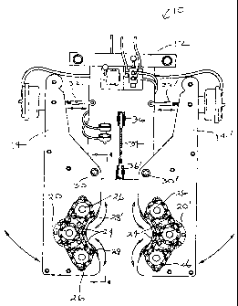
Fig. 1 is a top view of the invented power wrench with the chain guard removed
for clarity.
-2-
CA 02376577 2002-03-13
Fig. 2 is a top view of the power wrench depicted in Fig. 1, but with the
chain
guards installed, and with a large pipe engaged for spinning.
Fig. 3 is a top view of the power wrench depicted in Fig. 2, but with a
smaller
pipe engaged.
Fig. 4 is a partial, side cross-sectional view along lines 4-4 of Fig. 1.
With reference to the figures, several views of the invented power wrench 10
are
presented. The majority of the preferred components are shown and numbered in
all
figures and, for illustrative purposes, a pipe length in position for spinning
is included
in Figs. 2 and 3. To simplify the description, the components will be
separated into two
functional systems: the drive assembly and the engagement assembly.
The structural base for both systems is comprised of a T-shaped wishbone 12
and two engaging arms 14 and 14'. The wishbone 12 and engaging arms are shown
in top view in Figs. 1-3. The engaging arms 14 and 14' are constructed of a
top and
bottom cheek plate, 16 and 16', respectively with attendant bolts and spacers
as shown
in Fig. 4. The cheek plates 16 and 16' are moveably mounted to the wishbone 12
such
that the wings 18 of the wishbone are positioned between the top and bottom
cheek
plate, as shown in Fig. 4. These components are preferably constructed of 3/8"
T-1
steel plate, although those skilled in the art may substitute possible
alternatives. The
configuration of the arms and wishbone, such as the placement of axle holes
and
spacers, may vary to the extent that adjustment of the performance of the
essential
functions of each is still possible.
The drive assembly preferably includes two hydraulic motors 20 and 20', one on
each engaging arm. The motors are situated beneath the operating parts and are
protected by motor guards 22 and 22, respectively, as shown in Figs. 2 and 3.
Each
motor will drive a pair of drive chains 24 connected to a double sprocket
assembly 25.
The double sprocket assembly 25 preferably comprises an upper and lower
toothed
sprocket portion arranged co-axially on the motor-driven axle. The double
sprocket
drives two endless chain drives. At the end of each drive chain, opposite the
double
sprocket, are upper and lower roller sprockets 26 and 26', respectively. These
roller
sprockets are preferably situated at or near the top of the upper and lower
roller axles
such that the upper roller sprocket lies in the same plane as the upper doubie
sprocket
-3-
CA 02376577 2002-03-13
and the lower roller sprocket lies in the same plane as the lower double
sprocket. The
upper and lower roller double sprockets rotate the upper and lower drive
chains,
respectively. Other arrangements are possible where the desired interaction
between
the roller sprockets and the double sprocket is accomplished. The preferred
configuration incorporates 14-toothed sprockets with taper lock and number 50
chain
drives with 5/8" pitch. The roller axles extend through the top and bottom
cheek plates
and the ends are secured to the appropriate plate by means of a sealed ball
bearing or
other suitable connection. Rotation of the roller sprockets drives the distal
and proximal
rollers, 28 and 28', respectively, which engage and spin the subject pipe
length.
The serrated distal and proximal rollers are configured co-axially with the
upper
and lower roller sprockets. When engaged, the serrated surface grips the outer
surface
of the received pipe length to impart spin to the pipe. The toothed surface
significantly
enhances the frictional contact between the rollers and the drill pipe. The
rollers in the
preferred embodiment are approximately 5" in diameter and 3" wide. To initiate
spinning, the hydraulic motors are started slowly once the subject pipe length
is
clamped tightly between the two pairs of serrated rollers situated at the
forward end of
the engaging arms and surrounding the pipe-receiving space, as shown in Figs.
2 and
3.
Sufficient engagement of the drill pipe to the power rollers is accomplished
by
closing the engaging arms 14 and 14' tightly upon the pipe segment. The
engaging
arms of the preferred embodiment may be adjusted in two ways. Adjustment of
the
swivel pins 30 and 30' permits abduction and adduction of the engaging arms
along the
wishbone to make large adjustments. The swivel pins 30 and 30' may be secured
in
various positions along the wings of the wishbone to increase or decrease the
pipe-
receiving space as desired. Small adjustments, such as those required to fully
clamp
the pipe within the pairs of rollers, are accompiished via two compressed air
rams 32
and 32' that can be driven in or out. As shown in Figs. 1-3, the air rams 32
and 32' are
attached at their distal ends to the back end of the engaging arms, opposite
the rollers,
and one attached at their proximal ends to wishbone 12. This way, upon
actuation, the
air ram 32 and 32' generate a pivoting motion about the swivel pins. Extension
of the
air rams tightens the arms upon the pipe, and retraction of the rams releases
the drill
-4-
CA 02376577 2002-03-13
pipe segment. The engaging arms 14 and 14' are driven uniformly by the air
rams to
ensure that the drill rod segment contacts both sets of rotlers equally and
aligns with the
center of the receiving space.
The invented system allows the drill pipe segment to be clamped between the
engaging arms in firm contact with the serrated rollers. The pipe length may
then be
spun into, or out of, proper engagement with another pipe length to install or
remove
long drill strings. The mechanisms involved with engagement and driving of the
invented power wrench are both simple and reliable.
For use, the power wrench is typically suspended by a wire cable, or other
suitable connection, from a point at or near the top of a drill rig mast. In
one
embodiment, a cable 34 is connected to the two eyelets 36 and 36' on the power
wrench at a height appropriate for manual operation of the tool. The eyelets
36 and 36'
are positioned such that the cable 34 connected from one eyelet to the other
intersects
the center of gravity of the wrench. With the tool connected, secured, and
suspended
from the cable in this manner, the machine operator may easily grasp the
balanced
wrench by a pair of handles and position it near the subject drill pipe or
move it to an
out of the way place.
The wrench requires the use of a bracing mechanism when operational to
counteract the reactionary spinning forces imparted to the device by the drill
string. A
stop bar (not shown) is employed to brace the power wrench against an
available,
stable structure such as a mast post. The wrench must be started slowly to
allow the
stop bar to position itself securely against the mast or other structure.
To initiate operation of the tool, the safety mechanism must first be
inactivated.
This mechanism prevents unintentional activation of the machine due to
accidental
contact with the control levers. The safety comprises a means of locking the
compressed air control lever in an inactivated state that prohibits movement
of the lever
without first intentionally releasing the lever. When locked in place, the
safety prohibits
the arms from engaging. This allows operators and laborers to work safely
around the
device with minimal risk of accidental injury. When the mechanism is released
the arms
are free to close upon the subject drill rod. The safety is positioned so that
it is easily
within the reach of the operator.
-5-
CA 02376577 2002-03-13
To engage, the operator moves the wrench such-tliafthe arms surround, and
possibly contact, the subject drill rod and the air rams are then actuated to
clamp the
rod firmly between the pairs of rollers. With the arms engaged, the rollers
are turned by
the hydraulic motors until the spinning procedure is satisfactorily completed,
i.e., until
the male end of one rod is tightly seated within, or removed from, the female
end of
another.
Although this invention has been described above with reference to particular
means, materials and embodiments, it is to be understood that the invention is
not
limited to these disclosed particulars, but extends instead to all equivalents
within the
scope of the above description, included drawings and the following claims.
-6-