Note: Descriptions are shown in the official language in which they were submitted.
CA 02376756 2001-12-19
WO 01/78585 PCT/IBO1/00808
WAVEFRONT SENSOR FOR OBJECTIVE MEASUREMENT
OF AN OPTICAL SYSTEM AND ASSOCIATED METHODS
BACKGROUND OF THE INVENTION
s Cross-Reference to Related Application
This application claims priority from provisional application Serial No.
60/198,536, filed April 19, 2000, "Wavefront Sensor with an Extended Dynamic
Range and a Smail-Format CCD Detector."
Field of the Invention
The present invention relates to optical measurement systems and
methods, and, more particularly, to such systems and methods for objective
measurement of an eye.
15 Description of Related Art
Optical systems having a real image focus can receive collimated light and
focus it at a point. Such optical systems can be found in nature, e.g., human
and
animal eyes, or can be manmade, e.g., laboratory systems, guidance systems,
and the like. In either case, aberrations in the optical system can affect the
2o system's performance. By way of example, the human eye will be used to
explain
this problem.
A perfect or ideal eye diffusely reflects an impinging light beam from its
retina through the optics of the eye, which includes a lens and a cornea. For
such
an ideal eye in a relaxed state, i.e., not accommodating to provide near-field
25 focus, reflected light exits the eye as a sequence of plane waves: However,
an
eye typically has aberrations that cause deformation or distortion of
reflected light
CA 02376756 2001-12-19
WO 01/78585 PCT/IBO1/00808
2
waves exiting the eye. An aberrated eye diffusely reflects an impinging light
beam
from its retina through its lens and cornea as a sequence of distorted
wavefronts,
There are a number of technologies that attempt to provide the patient with
improved visual acuity. Examples of such technologies include remodeling of
the
cornea using refractive laser surgery or intra-cornea( implants, adding
synthetic
lenses to the optical system using intra-ocular lens implants, and precision-
ground
spectacles. In each case, the amount of corrective treatment is typically
determined by placing spherical and/or cylindrical lenses of known refractive
power at the spectacle plane (approximately 1.0-1.5 cms anterior to the
cornea)
1 o and literally asking the patient which lens or lens combination provides
the
clearest vision. This is an imprecise measurement of true distortions in the
reflected wavefront because (1) a single spherocylindrical compensation is
applied across the entire wavefront; (2) vision is tested at discrete
intervals (i.e.,
diopter units) of refractive correction; and (3) subjective determination by
the
15 patient is made in order to determine the optical correction. Thus
conventional
methodology for determining refractive errors in the eye is substantially less
accurate than the techniques now available for correcting ocular aberrations.
One method of measuring ocular refractive errors is disclosed in U.S.
Patent No. 5,258,791 to Penney et al. for "Spatially Resolved Objective
2o Autorefractometer," which teaches the use of an autorefractometer to
measure
the refraction of the eye at numerous discrete locations across the corneal
surface. Penney '791 further teaches the use of autorefractometer measurements
in determining an appropriate corneal surtace reshaping to provide emmetropia,
a
CA 02376756 2001-12-19
WO 01/78585 PCT/IBO1/00808
3
condition of a normal eye when parallel beams or rays of fight are focused
exactly
on the retina and vision is perfect.
By way of example, one method and system known in the art are disclosed
by Junzhong Liang et al, in "Objective Measurement Of Wave Aberrations of the
Human Eye with the Use of a Hartmann-Shack Wave-Front Sensor" [J. Opt. Soc.
Am. 11(7), July 1994, pp 1949-57]. Liang et al. teach the use of a
Hartmann-Shack wavefront sensor to measure ocular aberrations by measuring
the wavefront emerging from the eye by the retinal reflection of a focused
laser
light spot on the retina's fovea. The actual wavefront is reconstructed using
wavefront estimation with Zernike polynomials. A parallel beam of laser light
passes through beam splitters and a lens pair, which brings the beam to a
focus
point on the retina by the optics of the. eye. Possible myopia or hyperopia of
the
tested eye is corrected by movement of a lens within the lens pair. The
focused
light on the fovea is then assumed to be diffusely reflected and acts as a
point
~5 source located on the retina. The reflected light passes through the eye
and
forms a distorted wavefront in front of the eye that results from the ocular
aberrations. The aberrated wavefront is then directed to the wavefront sensor.
The Hartmann-Shack wavefront sensor disclosed by Liang et al. includes
2o two identical layers of cylindrical lenses with the layers arranged so that
lenses in
each layer are perpendicular to one another, as further disclosed in U.S.
Patent
No. 5,062,702 to Bille. In this way, the two layers operate as a two-
dimensional
array of spherical lenslets that divide the incoming fight wave into
subapertures.
CA 02376756 2001-12-19
WO 01/78585 PCT/IBO1/00808
4
The light through each subaperture is brought to focus in the focal plane of
the
lens array where a charge-coupled-device (CCD) image module resides.
The system of Liang et al. is calibrated by impinging an ideal plane wave of
light on the lenslet array so that a reference or calibrating pattern of focus
spots is
imaged on the CCD. Since the ideal wavefront is planar, each spot related to
the
ideal wavefront is located on the optical axis of the corresponding lenslet.
When a
distorted wavefront passes through the lenslet array, the image spots on the
CCD
are shifted with respect to a reference pattern generated by the ideal
wavefront.
Each shift is proportional to a local slope, i.e., partial derivatives of the
distorted
wavefront, which partial derivatives are used to reconstruct the distorted
wavefront, by means of modal wavefront estimation using Zernike polynomials.
However, the system disclosed by.Liang et al. is effective only for eyes
having fairly good vision. Eyes that exhibit considerable myopia (near-
sightedness) cause the focus spots to overlap on the CCD, thereby making local
slope determination practically impossible for eyes having this condition.
Similarly, eyes that exhibit considerable hyperopia (farsightedness) deflect
the
focus spots such that they do not impinge on the CCD, thereby again making
local
slope determination practically impossible for eyes having this condition.
Various embodiments of a method and system for objectively measuring
2o aberrations of optical systems by wavefront analysis have been disclosed in
commonly owned application Serial No. 09/566,668, "Apparatus and Method for
Objective Measurement and Correction of Optical Systems Using Wavefront
Analysis," filed May 8, 2000, which is hereby incorporated by reference
herein. In
this invention, an energy source generates a beam of radiation. Optics,
disposed
CA 02376756 2001-12-19
WO 01/78585 PCT/IBO1/00808
in the path of the beam, direct the beam through a focusing optical system
(e.g.,
the eye) that has a rear portion (e.g., the retina) that provides a diffuse
reflector.
The beam is diffusely reflected back from the rear portion as a wavefront of
radiation that passes through the focusing optical system to impinge on the
optics.
s . The optics project the wavefront to a wavefront analyzer in direct
correspondence
with the wavefront as it emerges from the focusing optical system. A wavefront
analyzer is disposed in the path of the wavefront projected from the optics
and
calculates distortions of the wavefront as an estimate of ocular aberrations
of the
focusing optical system. The wavefront analyzer includes a wavefront sensor
coupled to a processor that analyzes the sensor data to reconstruct the
wavefront
to include the distortions thereof.
A pertectly collimated light beam (i.e., .a bundle of parallel light rays,
here a
small-diameter, eye-safe laser beam) incident on a perfect, ideal emmetropic
eye,
focuses to a diffraction-limited small spot on the retina. This perfect
focusing is
true for all light rays passing through the entrance pupil, regardless of
position.
From the wavefront perspective, the collimated light represents a series of
perfect
plane waves striking the eye. The light emanates from an illuminated spot on
the
retina as wavefronts exiting as a series of perfect plane waves, which are
directed
onto a wavefront analyzer for measuring distortions from ideality.
2o In one embodiment, the radiation is optical radiation and the wavefront
sensor is implemented using a plate and a planar array of light-sensitive
cells. The
plate is generally opaque but has an array of light-transmissive apertures
that
selectively let impinging fight therethrough. The plate is disposed in the
path of
the wavefront so that portions of the wavefront pass through the light-
transmissive
CA 02376756 2001-12-19
WO 01/78585 PCT/IBO1/00808
6
apertures. The planar array of cells is arranged parallel to and spaced apart
from
the plate by a selected distance. Each portion of the wavefront passing
through
one of the light-transmissive apertures illuminates a geometric shape covering
a
unique plurality of cells.
The wavefront optical path relays the re-emitted wavefront from the corneal
plane to an entrance face of a Hartman-Shack wavefront sensor, The wavefront
incident on the sensor is received by a sensitive charged-coupled-device (CCD)
camera and an optical plate containing an array of lenslets. The lenslet array
is
parallel to the CCD detector face, with a distance therebetween approximately
equal to the focal length of each lens in the lenslet array. The lenslet array
divides
the incoming wavefront into a matching array of "wavelets," each of which
focuses
to a small spot on the CCD detector plane. The constellation of wavelet spots
in
the CCD is used to reconstruct the shape of the incident wavefront. Collimated
light striking the lenslet at normal (perpendicular) incidence would focus to
the
~5 spot on the CCD face where this optical axis intersects. The optics of the
apparatus provides such collimated light to the wavefront sensor using a
calibration optical path.
In the case of a reflected aberrated wavefront, light focuses to a spot
displaced from the collimated reference point by a distance D,~. The distance
from
2o the lenslet face to the CCD surface, Dz, is precisely known. Therefore,
dividing
the measured displacement, D,~, by the known propagation distance, DZ, the
slope
of the wavefront at the location of this lens element is determined. The same
calculation is applied in the y direction within the plane, and the entire
process
applied to every lenslet element irradiated by the wavefront. A mathematical
CA 02376756 2001-12-19
WO 01/78585 PCT/IBO1/00808
7
algorithm is then applied to reconstruct the wavefront shape consistent with
the
calculated D,~Dz and Dl/D~ slope data. Regardless of which wavefront sensor is
used, the distance between the planar array of cells and the opaque plate, or
the
array of lenslets, can be varied to adjust the slope measurement gain of the
wavefront sensor and thereby improve the dynamic range of the system.
Another measure of dynamic range enhancement is provided by the
focusing optics. The focusing optics includes first and second lenses
maintained
in fixed positions in the path of the beam and wavefront. An arrangement of
optical elements is disposed between the lenses in the path of the beam and
the
wavefront. The optical elements are adjustable to change the optical path
length
between the lenses. If an optical correction is desired, the distortions are
converted to an optical correction, which, if placed in the path of the
wavefront,
causes the wavefront to appear approximately as a plane wave. The optical
correction can be in the form of a lens or an amount of corneal material
ablated
~ 5 from the eye.
One method for determining aberrations of an eye, herein described by
way of example, includes directing a probe beam along a probe beam path toward
an eye, directing a fixation image along a fixation image path toward the eye,
directing a light source along a video image path toward the eye, generating a
2o video image of the eye, directing a wavefront originating from the eye
along a
wavefront path, wherein the probe beam path, the fixation image path, the
video
image path, and the wavefront path are coincident at least along a portion of
their
respective paths, the probe beam path terminating at the retina of the eye and
the
probe beam reflecting from the retina of the eye as a wavefront, aligning the
eye
CA 02376756 2001-12-19
WO 01/78585 PCT/IBO1/00808
with the probe beam path based at least in part on the video image of the eye
generated by the light source directed along the video image path, measuring
the
wavefront, and generating data representative of the aberrations of the eye
based
on the measurement of the wavefront. Further, the aligning of the eye with the
s probe beam path based at least in part on the video image of the eye
generated
by the light source directed along the video image path, may have the
wavefront
pass through a single microlens array.
SUMMARY OF THE INVENTION
It is an object of the present invention to provide a system and method for
objectively measuring ocular aberrations using a wavefront analyzer of simple
and
inexpensive design.
It is a further object to provide such an apparatus and method that can
employ a small-format camera.
~5 It is an additional object to provide a method for constructing such a
system.
These and other objects are achieved by the present invention, a wavefront
sensor that comprises an afocal relay stage for magnifying an incoming
wavefront
reflected from a source plane. In an exemplary application, a retina of an eye
2o reflects an impinging light beam thereon to form a series of wavefronts.
A lenslet array is positioned at a reference plane of the afocal relay stage
to
receive,the magnified wavefront. Further downstream is positioned a means for
imaging and demagnifying a focal plane image of the lenslet array at a final
image
CA 02376756 2001-12-19
WO 01/78585 PCT/IBO1/00808
9
plane. This demagnified image then serves as input to an analyzer, such as,
but
not intended to be limited to, a charge-coupled-device (CCD) camera.
The features that characterize the invention, both as to organization and
method of operation, together with further objects and advantages thereof,
will be
s better understood from the following description used in conjunction with
the
accompanying drawing. It is to be expressly understood that the drawing is for
the
purpose of illustration and description and is not intended as a definition of
the
limits of the invention. These and other objects attained, and advantages
offered,
by the present invention will become more fully apparent as the description
that
now follows is read in conjunction with the accompanying drawing.
BRIEF DESCRIPTION OF THE DRAWINGS
FIG. 1 (prior art) is a schematic diagram of an apparatus for wavefront
sensing.
15 FIG. Z is a schematic diagram of the apparatus of the present invention for
wavefront sensing.
DETAILED DESCRIPTION OF THE PREFERRED EMBODIMENTS
A description of the preferred embodiments of the present invention will
2o now be presented with reference to FIGS. 1 and 2.
CA 02376756 2001-12-19
WO 01/78585 PCT/IBO1/00808
The prior art apparatus 10 (FIG. 1 ) includes a first 11 and a second 12
afocal relay stage within the optical axis 13. The optical path through the
first
afocal relay stage 11 results in an image of the corneal plane 14 at a first
image
plane 15, which serves as an insertion point for a spherical trial lens, as
described
5 in application Serial No. 09/566,668.
The wavefront sensor comprises a microlens array plate and a charge-
coupled-device (CCD) camera at the second image plane 16 separated by a fixed
distance. The optical path 13 thus creates an image of the corneal plane 14 at
the
lenslet array, that is, at the entrance face of the actual wavefront sensor,
which
could be accomplished by a single afocal relay stage. Placing a spherical lens
into the optical axis 13 at the first image plane 15, in theory, could be used
to
remove the defocus wavefront error. This would potentially expand the dynamic
range of the apparatus 10. However, the trial lens approach is a moving
mechanism that can position lenses at the first image plane 15 with tremendous
accuracy and repeatability. It was therefore highly desirable that alternative
means be developed to address dynamic range.
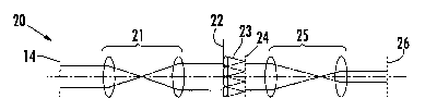
The present invention 20 (FIG. 2) accomplishes this by magnifying the
corneal plane 14 image with the first afocal stage 21. Magnification of the
wavefront reduces the wavefront slope, so that the displacement of the focused
2o fights spots on the CCD is decreased. The prior art design 10 does include
some
magnification in the second afocal stage 12 for this reason. The chosen
CA 02376756 2001-12-19
WO 01/78585 PCT/IBO1/00808
11
magnification factor used with that apparatus 10 at the second afocal stage 12
is
approximately 1.2, which is insufficient to cover the desired range in
refractive
errors. A magnification factor in excess of 1.5 is desirable for expanding the
use
of the apparatus 10. However, simply magnifying the corneal plane 14 has a
s drawback in that it necessitate a large-aperture wavefront sensor. That is,
both
the lens array and the CCD camera would preferably have large cross-sectional
areas to encompass the magnified image of the point of plane. This is not a
significant issue for the lens array plate; however, a large-format CCD camera
is
quite expensive, and such cameras are only available from a limited number of
vendors.
The apparatus 20 of the present invention solves this difficulty. The
corneal plane 14 is imaged at a reference plane 22 by the first afocal relay
stage
21. The first afocal relay stage 21 magnifies the corneal plane 14 by a
predetermined amount. A lenslet array plate 23 is placed at reference plane
22.
~5 Focused spots of light from an eye are produced at the lenslet array 23
focal
plane 24.
A second afocal relay stage 23 images the array focal plane 24 at a
camera plane 26, where the CCD is located. The second stage 25 may be other
than an afocal design, but preferably should provide demagnification of the
array
2o focal plane 24. This feature permits a small-active-area camera to be used
as the
light-recording element in the wavefront sensor. Specifics of the optical
design
CA 02376756 2001-12-19
WO 01/78585 PCT/IBO1/00808
12
are adjustable as desired to maximize performance for given camera and lenslet
array specifications.
It may be appreciated by one skilled in the art that additional embodiments
may be contemplated, including alternate optical elements to achieve similar
functions.
In the foregoing description, certain terms have been used for brevity,
clarity, and understanding, but no unnecessary limitations are to be implied
therefrom beyond the requirements of the prior art, because such words are
used
for description purposes herein and are intended to be broadly construed.
Moreover, the embodiments of the apparatus illustrated and described herein
are
by way of example, and the scope of the invention is not limited to the exact
details of construction.
Having now described the invention, the construction, the operation and
use of preferred embodiment thereof, and the advantageous new and useful
results obtained thereby, the new and useful constructions, and reasonable
mechanical equivalents thereof obvious to those skilled in the art, are set
forth in
the appended claims.