Some of the information on this Web page has been provided by external sources. The Government of Canada is not responsible for the accuracy, reliability or currency of the information supplied by external sources. Users wishing to rely upon this information should consult directly with the source of the information. Content provided by external sources is not subject to official languages, privacy and accessibility requirements.
Any discrepancies in the text and image of the Claims and Abstract are due to differing posting times. Text of the Claims and Abstract are posted:
| (12) Patent: | (11) CA 2376967 |
|---|---|
| (54) English Title: | SELF-CLEANING CONVEYOR ROLLER |
| (54) French Title: | ROULEAU DE CONVOYEUR AUTONETTOYANT |
| Status: | Term Expired - Post Grant Beyond Limit |
| (51) International Patent Classification (IPC): |
|
|---|---|
| (72) Inventors : |
|
| (73) Owners : |
|
| (71) Applicants : |
|
| (74) Agent: | PIASETZKI NENNIGER KVAS LLP |
| (74) Associate agent: | |
| (45) Issued: | 2006-10-31 |
| (22) Filed Date: | 2002-03-15 |
| (41) Open to Public Inspection: | 2003-09-15 |
| Examination requested: | 2003-02-04 |
| Availability of licence: | N/A |
| Dedicated to the Public: | N/A |
| (25) Language of filing: | English |
| Patent Cooperation Treaty (PCT): | No |
|---|
| (30) Application Priority Data: | None |
|---|
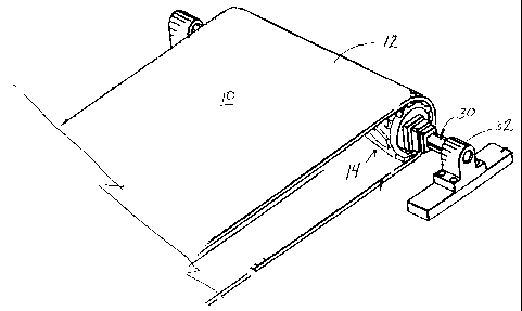
a self cleaning conveyor roller for supporting a conveyor media carrying contaminant materials. The conveyor roller consists of a drum defining a support surface, having a generally cylindrical shape, and being adapted to be supported for rotation, for supporting a conveyor media. The conveyor roller having a plurality of abutments on the support surface, raised above the support surface, and defining a series of spaced apart conveyor media support surfaces lying on a circular configuration, concentric with the drum. The abutments are arranged in a generally chevron shapes, around the drum. During rotation of the conveyor roller the abutments cause any debris or contaminants between the roller and the conveyor media to be guided out of the conveyor system.
Un rouleau de convoyeur autonettoyant pour soutenir un support de convoyeur transportant des matières contaminantes. Le rouleau de convoyeur est constitué d'un tambour définissant une surface de support, ayant une forme généralement cylindrique, et étant adapté pour être supporté pour un effet de rotation, destiné à soutenir un support de convoyeur. Le rouleau de convoyeur comportant une pluralité de butées sur la surface de support, soulevées au-dessus de la surface de support, et définissant une série de surfaces de support de support de convoyeur espacées se trouvant sur une configuration circulaire, concentrique avec le tambour. Les butées sont disposées dans une forme généralement de chevron, autour du tambour. Pendant la rotation du rouleau de convoyeur, les butées entraînent tous débris ou contaminants entre le rouleau et le support de convoyeur à être dirigés en dehors du système de convoyeur.
Note: Claims are shown in the official language in which they were submitted.
Note: Descriptions are shown in the official language in which they were submitted.
2024-08-01:As part of the Next Generation Patents (NGP) transition, the Canadian Patents Database (CPD) now contains a more detailed Event History, which replicates the Event Log of our new back-office solution.
Please note that "Inactive:" events refers to events no longer in use in our new back-office solution.
For a clearer understanding of the status of the application/patent presented on this page, the site Disclaimer , as well as the definitions for Patent , Event History , Maintenance Fee and Payment History should be consulted.
| Description | Date |
|---|---|
| Inactive: Expired (new Act pat) | 2022-03-15 |
| Common Representative Appointed | 2019-10-30 |
| Common Representative Appointed | 2019-10-30 |
| Maintenance Request Received | 2014-03-10 |
| Maintenance Request Received | 2013-03-07 |
| Revocation of Agent Requirements Determined Compliant | 2007-11-13 |
| Inactive: Office letter | 2007-11-13 |
| Inactive: Office letter | 2007-11-13 |
| Appointment of Agent Requirements Determined Compliant | 2007-11-13 |
| Grant by Issuance | 2006-10-31 |
| Inactive: Cover page published | 2006-10-30 |
| Inactive: Final fee received | 2006-08-10 |
| Pre-grant | 2006-08-10 |
| Inactive: IPC from MCD | 2006-03-12 |
| Notice of Allowance is Issued | 2006-02-13 |
| Letter Sent | 2006-02-13 |
| Notice of Allowance is Issued | 2006-02-13 |
| Inactive: Office letter | 2005-12-06 |
| Inactive: Approved for allowance (AFA) | 2005-11-09 |
| Amendment Received - Voluntary Amendment | 2005-03-31 |
| Inactive: S.30(2) Rules - Examiner requisition | 2004-10-01 |
| Inactive: Office letter | 2004-04-13 |
| Inactive: Office letter | 2004-04-13 |
| Revocation of Agent Requirements Determined Compliant | 2004-04-13 |
| Appointment of Agent Requirements Determined Compliant | 2004-04-13 |
| Appointment of Agent Request | 2004-03-15 |
| Revocation of Agent Request | 2004-03-15 |
| Inactive: Correspondence - Formalities | 2003-12-18 |
| Inactive: Office letter | 2003-09-23 |
| Application Published (Open to Public Inspection) | 2003-09-15 |
| Inactive: Cover page published | 2003-09-14 |
| Inactive: Entity size changed | 2003-03-04 |
| Letter Sent | 2003-02-27 |
| Request for Examination Received | 2003-02-04 |
| Request for Examination Requirements Determined Compliant | 2003-02-04 |
| All Requirements for Examination Determined Compliant | 2003-02-04 |
| Inactive: Single transfer | 2003-02-04 |
| Inactive: Correspondence - Formalities | 2003-02-04 |
| Inactive: First IPC assigned | 2002-06-13 |
| Inactive: Filing certificate - No RFE (English) | 2002-04-18 |
| Filing Requirements Determined Compliant | 2002-04-18 |
| Application Received - Regular National | 2002-04-18 |
There is no abandonment history.
The last payment was received on 2006-03-14
Note : If the full payment has not been received on or before the date indicated, a further fee may be required which may be one of the following
Please refer to the CIPO Patent Fees web page to see all current fee amounts.
Note: Records showing the ownership history in alphabetical order.
| Current Owners on Record |
|---|
| VAN DER GRAAF, INC. |
| Past Owners on Record |
|---|
| ALEXANDER DIMITRIUS KANARIS |

