Note: Descriptions are shown in the official language in which they were submitted.
CA 02377210 2002-03-18
1
OPTICAL STRUCTURE FOR THE COMPENSATION OF CHROMATIC
DISPERSION IN A LIGHT SIGNAL
FIELD OF THE INVENTION
The present invention relates to the compensation of chromatic dispersion
occurring in waveguides such as optical fibers. More specifically, the
invention
concerns an optical structure for dispersion compensation based on a Bragg
grating, and operating at several wavelengths or Wavelength-Division-
Multiplexing
(WDM) channels.
BACKGROUND OF THE INVENTION
In optical telecommunication systems, one of the many difficulties
encountered is the chromatic dispersion of light signals propagating over long
distances in optical fibers. The chromatic dispersion in non-dispersion-
shifted
optical fiber is nominally 17 pslnmlkm in the 1550 nm telecommunication
window,
but this value changes as a function of the wavelength: its value changes by
about
2 ps/nm/km between 1530 nm and 1565 nm. Several single-channel dispersion
compensators based on Fiber Bragg gratings (FBGs) have been proposed, and
although this solution was demonstrated to be an appropriate solution for
compensating the chromatic dispersion in a single WDM channel, for multi-
channel
systems, the spectral variation of the chromatic dispersion must be taken into
account, especially for data transmission systems operating at high rates such
as
10 and 40 Gbitls. There is therefore a need for a broadband dispersion
compensator that compensates for the chromatic dispersion but also for its
spectral variation. This feature is often referred to as the slope
compensation.
Fiber Bragg gratings are a well established technology for the fabrication of
components for optical telecommunications, especially for WDM. Basically, a
Bragg grating allows light propagating into an optical fiber to be reflected
back
when its wavelength corresponds to the grating's Bragg wavelength, related to
its
period. A chirped Fiber Bragg Grating, in which the grating period varies as a
function of the position along the fiber, represents a well known solution for
Y
CA 02377210 2002-03-18
2
compensating the chromatic dispersion of an optical fiber fink (F. Ouellette,
"Dispersion cancellation using linearly chirped Bragg grating frlters in
optical
waveguides," Opt.Lett., 12, pp.847-849, 1987; R.Kashyap, "FiberBragg
gratings,"
Academic Press, 458p., 1999). Such a grating compensates for the accumulated
dispersion since the group delay varies as a function of the wavelength. An
appropriate grating can be fabricated such that the wavelength dependence of
its
group delay is just the opposite of that of the fiber link. Different
solutions based on
FBGs have been proposed for broadband dispersion compensation but most of
them do not include the slope compensation.
Referring to M Durkin et al. "7 m long continuously written fibre 8ragg
grating for combined second- and third order dispersion compensation",
Electron.
Lett. 33, pp 1891-1893 (1997) and J.F. Brennan et al. in BGPP 1999, pp.35-37,
ultra-long FBGs, up to 10m; have been demonstrated for dispersion compensation
over a large bandwidth. However, such devices suffer from high group delay
ripples. The group delay of a compensator based on ultra-long FBGs is
schematically illustrated in F1G. 1 (prior art). The chromatic dispersion the
device
compensates for is given by the slope of the group delay. The example shown in
FIG. 1 has a dispersion of -1250 pslnm and thus compensates for the chromatic
dispersion accumulated over a 73 km long fiber link.
Sampled FBGs and Moire FBGs have also been proposed in U.S. Patent
no. 5,384,884 (KASHYAP et al.) noteworthy for multi-channel dispersion
compensation (see for example A.E.Willner, et al., "Tunable compensation of
channel degrading effects using nonlinearly chirped passive fiber Bragg
gratings,"
IEEE J. of Selected Topics in Quantum Electron., 5, pp.1298-1311 (1999), U.S.
Patent no. 5,982,963 (FEND et al.); A.V.Buryak et al., "Novel multi-channel
grating
designs", Proceedings of BGPP 2001; and M.Ibsen et al., "Chirped moue fiber
gratings operating on two-wavelength channels for use as dual channel
dispersion
compensators," IEEE Photon. Technol. Lett., 10, pp.84-86, (1998)) in which the
sampling function replicates a given dispersion function (M. Ibsen et al,
"Sine-
sampled fiber Bragg gratings for identical multiple wavelength operation,"
IEEE
Photon. Technol. Lett., 10, pp.842-844, 1998). As a result, all the channels
are
CA 02377210 2002-03-18
3
identical and the resulting device cannot compensate for the dispersion slope.
The
group delay of such a compensator based on a sampled FBG is schematically
illustrated in FIG. 2 (prior art). An approach for mufti-channel slope
compensation
has been proposed based on interleaved sampled Bragg gratings in W H Loh et
al.
"Sampled fiber grating based dispersion slope compensafo~", »Photonics
Technol.
Lett. 11, no 10, pp 1280-1282 (1999). The theoretical approach is expected to
suffer from significant practical difficulties associated with the control of
the many
micro-grating structures.
Single-channel non-linearly chirped FBGs have been proposed for
narrowband dispersion slope compensation (J.A.R.Williams et al., "Fiber Bragg
grating fabrication for dispersion slope compensation," IEEE Photon. Technol.
Lett., 8, pp.1187-1189,.1996). In order to achieve operation over a broader
range,
mufti-channel non-linearly chirped FBGs were proposed (Y. Xie et al., "Tunable
compensation of the dispersion slope mismatch in dispersion-managed systems
using a sampled nonlinearly chirped FBG," IEEE Photon. Technol. Lett., 12,
pp.1417-1419, 2000). This last approach allows a tuning of the dispersion but
the
spectral duty factor is limited to about 25%.
OBJECTS AND SUMMARY OF THE INVENTION
It is an object of the present invention to provide an optical structure
allowing the compensation for both the chromatic dispersion of light signals
and
the dispersion slope.
It is a preferred object of the present invention to provide a mufti-channel
dispersion compensator based on such an optical structure.
Accordingly, in accordance with a first aspect of the invention, there is
provided an optical structure for the compensation of chromatic dispersion in
a
light signal having a plurality of wavelength channels, each wavelength
channel
having accumulated a different chromatic dispersion.
The optical structure includes an optical waveguide having a light
propagation axis, and a Bragg grating provided in the waveguide across the
light
propagation axis. The Bragg grating has a plurality of grating components each
5.
CA 02377210 2002-03-18
associated with one or a few of the wavelength channels, and having a
spatially
variable period chosen to compensate for the chromatic dispersion of this or
these
wavelength channels.
In accordance with a second aspect of the present invention, there is
having accumulated a different chromatic dispersion.
In accordance with a second aspect of the invention, there is also provided
a multi-channel dispersion cornpensator for the compensation of chromatic
dispersion in a light signal having a plurality of wavelength channels, each
wavelength channel having accumulated a different chromatic dispersion.
The compensator includes an optical structure having an optical waveguide
having a light propagation axis, and a Bragg grating provided in this
waveguide
across the Light propagation axis. The ~ Bragg grating has a plurality of
grating
components each reflecting one or a few of the wavelength channels and having
a
spatially variable period chosen to compensate for the dispersion of this or
these
wavelength channels.
The compensator also includes an optical coupling device coupled to the
optical waveguide. The optical coupling device has an input port for receiving
the
light signal, an input/ouput port for propagating this light signal in the
optical
structure and receiving a reflection thereof by the Bragg grating, and an
output port
for outputting the reflected light signal.
In accordance with a third aspect of the present invention, there is also
provided a mufti-channel dispersian compensator for the compensation of
chromatic dispersion in a light signal having a plurality of wavelength
channels,
each wavelength channel having accumulated a different chromatic dispersion.
The compensator includes an optical waveguide having a light propagation axis.
A
plurality of optical structures are provided in this waveguide across the
light
propagation axis, each of these optical structures comprising a Bragg grating
having a plurality of grating components. Each grating component reflects one
or a
few of the wavelength channels, and has a spatially variable period chosen to
5 provided another optical structure for the compensation of chromatic
dispersion in
a light signal having a plurality of wavelength channels, each wavelength
channel
CA 02377210 2002-03-18
compensate for the dispersion of this or these channels. The compensator also
includes an optical coupling device coupled to the optical waveguide. The
optical
coupling device has an input port for receiving the light signal, an
inputlouput port
for propagating this light signal in the optical waveguide and receiving a
reflection
5 thereof by the Bragg gratings of the optical structures, and an output port
for
outputting the reflected light signal.
Other features and advantages of the present invention will be better
understood upon reading of preferred embodiments thereof with reference to the
appended drawings.
BRIEF DESCRIPTION OF THE DRAWINGS
FIG. 1 (PRIOR ART) is a graph of the group delay of a broadband
dispersion compensator based on ultralang chirped Fiber Bragg Gratings.
FIG. 2 (PRIOR ART} is a graph of the group delay of a broadband
dispersion compensator based on sampled chirped Fiber Bragg Gratings in which
all the channels are identical.
FIG. 3 is a schematized representation of an optical structure according to a
first preferred embodiment of the invention.
FIG. 4 is a schematized representation of an optical structure according to a
second preferred embodiment of the invention.
FIG. 5 is a graphics! representation of the reflectivity spectrum of light
reflected by an optical structure according to the invention.
FIG. 6 is a graphical representation of the group delay slope for each
channel reflected by an optical structure according to the invention.
FIG. 7A is a schematized representation of a mufti-channel dispersion
compensator according to a preferred embodiment of the present invention. FIG.
7B shows a variant to the embodiment of FIG. 7A.
FIG. 8A is a schematized representation of a mufti-channel dispersion
compensator according to another preferred embodiment of the present
invention.
FIG. 8B shows a variant to the embodiment of FlG. 8A.
CA 02377210 2002-03-18
6
FIGs. 9A and 9B respectively show the reflectivity and group delay spectra
of a 12-channel third-order dispersion compensation grating; FIG. 9C is a
graph
where the dots represent the dispersion values obtained from a curve fit of
the
group delay while the solid line represents the target.
FIGs. 10A and 10B respectively show the reflectivity and group delay
spectra of a 12-channel dispersion slope compensation grating; FIG. 10C is a
graph where the dots represent the dispersion values obtained from a curare
fit of
the group delay while the solid line represents the target.
DESCRIPTION OF PREFERRED EMBODIMENTS OF THE INVENTION
The present invention provides an optical structure which can compensate
for the- chromatic dispersion accumulated by a light signal aver a certain
propagation distance, but also for the channel-to-channel dispersion
variations.
A single-channel Bragg grating is described by its longitudinal index profile
which can be written as:
n(z) - nN~.(z) + ~n(z)sin ~(zj
(1 )
where z is the position along the axis of the waveguide, ne~(z) is the
averaged effective index (considered to vary only slowly along the axis),
~n(z) is
the amplitude of the index modulation which can vary along the axis in order
to
include, for example, an apodization profile, and p(z) is the grating period,
which
can also vary along the axis. For commodity, the z axis is defined such that
z=0
corresponds to the center of the grating.
A Bragg grating can compensate for the chromatic dispersion when it is
linearly chirped, that is, when its period varies linearly along the z axis
according
to:
PAZ) Pa + a ' = . (2)
The grating reflects fight having a wavelength equal (or close) to the Bragg
wavelength given by:
CA 02377210 2002-03-18
c
7
~a~z) - 2 n~~. P(z) , (3)
The Bragg wavelength ~,B(z) varies along the grating when the period varies
monotonously as a function of z. Light having a wavelength ~,e{z) is reflected
by
the grating at location z while light having a wavelength ~,a(z+~z) is
reflected at
location z+0z. With respect to the fight of wavelength ~.e(z), the light of
wavelength
~,e(z+pz) is delayed in time by a group delay atg given by:
2 ~.z ng
-
(4)
where ng is the group index of the fiber and c is the light velocity in
vacuum.
The dispersion D is the wavelength derivative of the group delay. Assuming
that
~z is small, D is given by:
~t& y~g a
~a (z + ~z) - ~.a (z) z d ' (5)
c n~~ ~ ~ P{z)J
In the case of p(z) given by Equation (2), the dispersion of the grating can
compensate for reduces to:
z
- n~~ ~ (6)
c np~,.- a
Higher order dispersion compensation can aiso be taken into account by
using a non-linearly chirped Bragg grating having a period given by:
p(z) - P~+crvz+~~z2+y~za+... (~)
A multi-channel Bragg grating is basically a combination of several Bragg
grating components and reflects light having a wavelength equal (or close) to
several Bragg wavelengths, lts longitudinal index profile can be written as:
~" 2 ~ z
h(z) - ~~,~ (z) + ~~n; (z) sin + ~t , (8)
=i Pr ~')
y CA 02377210 2002-03-18
8
where m is the number of grating components, dn;(z) are the spatially-
dependent index modulation amplitudes, ~ are the phases of each of the
components and p,~z) are the spatially-dependent periods given by:
Pf(Z) - Pai +ai'Z+~r'Z3 +yi'23 +... , {9)
A mufti-channel Bragg grating can be used as a broadband third-order
dispersion compensator if the periods p;(z) are properly chosen. Suppose that
m
channels centered at wavelengths ~,; must be compensated with dispersion
values
D; respectively. Assuming that intra-channel compensation is achieved at the
second-order only, the periods p;{z) must be given, for i=1 to m, by:
z
Pr ~Z) - ~' + n82 ' Z ~ ('! 0)
2 ~N~n ~ ~r~- D~
It can be noted that the relative component phases ø~ may be chosen
arbitrarily, even randomly, or selected in order to minimize the maximum index
value along the grating.
The present invention therefore provides an optical structure for the
compensation of chromatic dispersion in a light signal having a plurality of
wavelength channels, based on the principles explained above.
Referring to FIG. 3, there is schematized an optical structure 10 according
to a preferred embodiment of the present invention. It includes an optical
' waveguide 12, such as a length of optical fiber, having a light propagation
axis z. A
Bragg grating 14 is provided in the waveguide 12, across the light propagation
axis
z. The Bragg grating 14 is made of a plurality of grating components (c~, c2,
... c").
Each component is associated with a limited number. of the wavelength channels
of the light signal, a single one or a few; and has a spatially variable
period chosen
to compensate for the chromatic dispersion of this or these particular
channels. In
this manner, the dispersion compensation provided by the Bragg gratings takes
into account the variations in dispersion experienced by each different
channel. As
one skilled in the art will readily understand, the limited number of channels
is
CA 02377210 2002-03-18
9
selected to include a few neighboring channels having dispersion
characteristics
close enough to be efficiently compensated by a single grating component.
Typically, less than 10 channels would be an appropriate number; although' a
higher number could be considered if the properties of a given system allowed
it.
In the embodiments described hereinafter, each grating component will be
considered associated with only one wavelength channel, for simplicity, but it
is
understood that the invention should not be limited to such an embodiment.
Preferably, the Bragg grating 14 defines a longitudinal refractive index
profile in the optical waveguide 12 as defined by equation (8). As explained
above, the relative phase ~; of each grating component can be selected in
order to
minimize the maximum value of the longitudinal index profile n(z) along the
propagation axis, or can be alternatively arbitrarily or randomly selected.
Each
grating component is preferably linearly chirped, and is preferably chosen
according to equation (10). In the alternative, the grating components may be
non
linearly chirped.
In the embodiment of FiG. 3, the grating components are superimposed and
thereby form a compact structure. This may for example be achieved by using
one
different phase mask per grating component. As another example, the same Bragg
grating may be manufactured by using a single phase mask, changing the Bragg
wavelength by stretching the fiber and finely adjusting the chirp of each
component
using chirp adjustment techniques, such as for example disclosed in Y.
Painchaud
et al. "Chirped fibre gratings produced by filling the t<bre", Electron. Lett"
31, pp
171-172 (1995); M. Cole et al., "Moving fibrelphase mask scanning beam
technigue for enhanced flexibility in producing fibre gratings wifh uniform
phase
mash', Electron. Lett. 31, pp 1488-1490 (1995); and U.S. patents nos.
5,903,689
(PAINCHAUD et al.) and 6,072,926 {COLE et al.). Another alternative would be
to
use holographic writing techniques which allow flexibility in the aratina
characteristics. A complex mufti-period phase mask may also be used for an
easy
fabrication of the mufti-channel grating. In the alternative the novel
technique
disclosed in a jointly filed application entitled "METHOD AND APPARATUS FOR
CA 02377210 2002-03-18
y
1
RECORDING AN OPTICAL GRATING IN A PHOTOSENSITIVE MEDIUM" to the
same assignee, could be used.
Referring to FIG. 4, there is illustrated another embodiment of the present
invention where the grating components are concatenated, and may for example
be manufactured using one of the techniques described above.
FIGs. 5 and 6 respectively show the reflectivity peaks of the resulting
structure for each grating component, and their group delays. As may be seen,
the
group delay slope may be selected to be different for each channel in order to
be
tailored to the dispersion experienced by each particular channel.
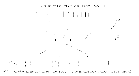
Referring to FIGs. 7A, 7B, 8A and 8B, the present invention also provides a
multi-channel dispersion compensator 20.
The compensator 20 includes an optical structure 10 as described above,
that is an optical waveguide 12 having a light propagation axis z, and at
least one
Bragg grating 14 provided in the waveguide 12 across the light propagation
axis z.
In the embodiments of FIGS. 7A and 8A a single optical structure 10 is
provided,
whereas a plurality of them are shown in FIGs. 7B and 8B. Each Bragg grating
has
a plurality of grating components, each associated with one or a few of the
wavelength channels and having a spatially variable period chosen to
compensate
for the dispersion of this channel (or these few channels}.
The compensator 20 further includes an optical coupling device 22 coupled
to the optical waveguide 12. The optical coupling device 22 has an input port
24
for receiving the light signal, an input/output port 25 for propagating it in
the optical
waveguide of the optical structure 10, where it is reflected by the Bragg
grating,
and an output port 26 for outputting the light signal reflected by the Bragg
grating
(or Bragg gratings}.
In FIGs. 7A and 7B, the coupling device 22 is embodied by an optical
circulator. In FIGs. BA and 8B, it is embodied by an optical coupler such as a
fused
coupler. Any other device appropriate to perform a coupling function is
considered
to be within the scope of the present invention.
Superimposed grating components in which the chirp of each grating
component is slightly different can be used as a third-order dispersion
CA 02377210 2002-03-18
11
compensator. Referring to FIGs. 9A, 9B and 9C, there is shown an example of a
multi-channel dispersion compensation grating that could compensate up to the
third-order the dispersion accumulated over 50 km of SMF-28 fiber.
Superimposed grating components in which the chirp of each grating is
different, can also be used as a dispersion slope compensator. Such a
dispersion
slope compensator is of interest in complement to existing broadband
dispersion
compensation devices such as Dispersion Compensating Fiber (DCF). The DCF
compensates properly for one channel, but since its dispersion slope does not
match the one of the transport fiber, an incomplete compensation occurs at the
other channels. A dispersion slope compensator can then be used to precisely
adjust the compensation of all the wavelength channels. For exemple, in 20
consecutive sections of 80 km of SMF-28 fiber each followed by 13.6 km of
dispersion compensating fiber {DCF), the spectral variation of the overall
dispersion is 36 ps/nm2. This variation is due to the fact that the DCF
compensates
for the dispersion but only for about 60% of the dispersion slope. FIGS 10A,
10B
and 10C show an example of a multi-channel dispersion compensation grating
that
provides such a dispersion variation.
In addition, to achieve a device in which the dispersion is different channel-
per-channel, intra-channel variation of the dispersion can be taken into
account.
Instead of being linear, non-linear variation of the group delay as a function
of the
wavelength can be achieved. This can be of interest for intra-band slope
compensation (see J.A.R. Williams et al. "Fiber 8ragg grating fabrication for
dispersion slope compensation", IEEE Photon. Technol. Lett. 8, pp 1187-1189
(1996)). Intra-channel non-linearity may also be desired for tuning
applications
(see A.E.Willner, et al., "Tunable compensation of channel degrading effects
using
noniinearly chirped passive fiber Bragg gratings," IEEE J. of Selected Topics
in
Quantum Electron., 5, pp.1298-1311 (1999), U.S. patent no. 5,989,963 (FENG et
al.) and J.A.. Fells et al. "Twin fibre grating adjustable dispersion
compensator for
40 Gbits/s", Proc. ECOC 2000).
i
CA 02377210 2002-03-18
12
0f course, numerous changes or modifications could be made to the
embodiments described above without departing from the scope of the invention
as defined in the appended claims.