Note: Descriptions are shown in the official language in which they were submitted.
CA 02377635 2002-03-20
CORDLESS BLIND
FIELD OF INVENTION
The invention relates to lift systems for raising and lowering window blinds
that have lift cords such as pleated shades, roman shades and venetian blinds.
BACKGROUND OF THE INVENTION
Venetian type blinds have a series of slats hung on ladders that extend from a
headrail to a bottomrail. In most venetian blinds a pair of lift cords is
provided each
having one end attached to the bottomrail and then passing through elongated
holes in
the slats up to and through the headrail. When the lift cords are pulled
downward the
blind is raised and when the lift cords are released the blind is lowered. A
cord lock is
usually provided in the headrail through which the lift cords pass. The cord
lock
allows the user to maintain the blind in any desired position from fully
raised to fully
lowered. Pleated shades and roman shades are also raised and lowered by lift
cords
running from the bottom of the shade into a headrail. The cord lock system and
other
cord lift systems used in venetian blinds can also be used in pleated shades
and roman
shades.
Another type of lift system for window blinds utilizes a take-up tube for each
lift cord.
These tubes are contained on a common shaft within the headrail. Each lift
cord is
attached to one end of a tube. The tubes are rotated to wind or unwind the
lift cord
around tubes. This system is generally known as a tube lift system. Some tube
lift
systems are operated by a continuous loop cord that passes over one end of the
axle
and extends from the headrail.
CA 02377635 2002-03-20
-2-
In recent years the art has been concerned that cords, particularly looped
cords, pose a strangulation threat to children who may become entangled in the
cords.
Consequently, there has been much interest in cordless blinds. These blinds
rely on
electric motors or spring motors to raise and lower the lift cord. One common
cordless blind simply contains a motor connected to a tube collection system
within
the headrail. Another cordless blind relies upon a constant force spring motor
attached to a spool or spools on which the lift cords are collected. This type
of
cordless blind is disclosed by Coslett in United States Patent No. 5,105,867
and by
Kuhar in United States Patent Nos. 5,482,100; 5,531,257 and 6,079,471.
Coslett discloses a sun shade having a series of blades connected together to
form a serrated shape like a pleated shade. The upper blade is mounted within
a
hollow housing and the lower blade is secured to a plate member. A constant
force
spring plate is wound around a spring spool member and further engaged to an
output
spool, both of which are within a hollow handle secured to the hollow housing.
A
cord is connected to the output spool and passed from the handle through the
housing
and the blades and is connected to the plate member. Such a cording
arrangement is
similar to that of a lift cord in a pleated shade or venetian blind. The
spring retains
the blades in a folded closed position. When the shade is extended the spring
exerts
tension on the cord. Consequently, Coslett teaches the user to fix the plate
member
along one side of the window and to provide a hook to retain the hollow
housing at
the opposite side of the window when the shade is covering the window. Thus,
Coslett's shade can be in only one of two positions, fully extended to cover
the
window or fully retracted. Furthermore, Coslett's blind is not suitable for
installation
in an orientation in which one rail is fixed at the top of the window frame as-
is done
CA 02377635 2002-03-20
-3-
for most building windows. That is so because when the blind is fully
retracted most
people could not reach the handle to extend or close the blind without
standing on a
stool or ladder.
Kuhar discloses a cordless, balanced blind that contains at least one constant
variable force spring motor in the headrail. The springs in these motors vary
in
thickness or in width along their length as they axe wound around storage
drums. A
cord spool is coupled to one or more spring drums. The lift cords of the blind
are
wound about the spool. Thus, the spring winds or unwinds as the blind is
raised or
lowered. The difference in width or thickness of the spring compensates for
the
increasing weight of the blind on the cords as the window covering is raised
and the
decreasing weight as the blind is lowered. Kuhar teaches that much effort be
made to
select and couple the spring motor to the cords so that the bottomrail is
balanced at
any and every position. Kuhar further teaches that several spring motors may
be
coupled together.
Placing the spring motors in the headrail as taught by Kuhar requires that the
headrail be tall enough and wide enough to accommodate the spring motors.
Consequently, the headrail must be larger than would be required if no spring
motors
were in the hea,drail. If one placed the spring motors in the bottomrail, a
smaller
headrail could be used; however, the weight of the bottomrail would be
increased.
Increasing the weight of the bottomrail would make it much more expensive to
balance the bottomrail in any and every position as Kuhar teaches is critical.
Perhaps
this could be accomplished with more or larger spring motors, but that would
change
the dynamics of the blind. For that reason one following the teachings of
Kuhar would
be lead away from putting spring motors in the bottomrail.
CA 02377635 2002-03-20
-4-
SUMMARY OF THE INVENTION
I provide a cordless blind containing one or more springs in the bottomrail of
the blind. Preferably the spring is a constant force spring motor of the type
disclosed
by Coslett and Kuhar. The spring motor is connected to at least one cord
collector in
a manner to maintain tension on the cord collector. The tension causes the
lift cords
to be collected on the cord collector when the cord collector and the lift
cords are free
to move, thereby moving the bottomrail toward the headrail. I further provide
a lock
mechanism attached to the cord collector or the lift cords. The lock mechanism
has a
locked position wherein the lift cords are restrained from being collected on
the cord
collector and has an unlocked position that allows the cord collector and
plurality of
lift cords to move freely. I prefer that the lock mechanism be biased toward a
locked
position. However, a two position, i.e. locked or unlocked, lock mechanism
could be
used. I further prefer to provide a button on the bottomrail to operate the
lock
mechanism.
The cordless blind of the present invention is easy to operate. A user simply
presses the button to release the lock and either pulls the bottomrail down or
allows
the spring motor to raise the bottomrail. When the button is released the lock
engages
if the lock is of the type that is biased to a locked position. If a two
position lock is
used the user presses the button, moves the bottomrail to a desired position
and
presses the button again to lock the lock mechanism. Because the lift cords
and cord
collector are no longer free to move, the bottomrail stays in the position
where it was
when the button was released.
CA 02377635 2002-03-20
-S-
This cordless blind could be a pleated shade, a cellular shade, a roman shade
or a venetian blind. If the shade is a venetian blind I prefer to provide
ladders in
which the rails of the ladders are connected to form a continuous loop. Then
the slats
can be tilted with a conventional tilt mechanism in the headrail.
BRIEF DESCRIPTION OF THE FIGURES
Figure 1 is a rear perspective view of a present preferred embodiment of my
cordless blind.
Figure 2 is a sectional view taken along the line II-II of Figure 1 wherein a
portion of the front wall of the bottomrail has been cut away.
Figure 3 is an enlarged view of the spring motor in the embodiment shown in
Figures 1 and 2.
Figure 4 is a perspective view similar to Figure 3 of an alternative spring
motor that can be used in the cordless blind of the present invention.
Figure 5 is a front view of three interconnected spring motors that can be
used
in the cordless blind of the present invention.
Figure 6 is a front view of two interconnected spring motors that can be used
in the cordless blind of the present invention.
Figure 7 is an end view of a ladder and associated pulleys that can be used
when the cordless blind of the present invention is configured as a venetian
blind.
Figure 8 is a front view of an alternative motor and lock mechanism for a
second present preferred embodiment of my cordless blind.
Figure 9 is a perspective view of a bottomrail partially cut away to show for
a
third present preferred embodiment of my cordless blind.
CA 02377635 2002-03-20
-6-
Figure 10 is a schematic representation of a fourth present preferred
embodiment of my cordless blind.
DESCRIPTION OF THE PREFERRED EMBODIMENTS
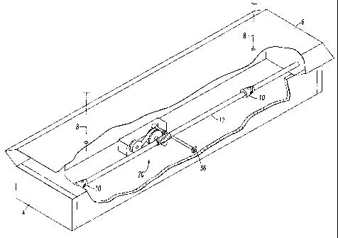
A present preferred embodiment of my cordless blind shown in Figure 1 is
comprised of a headrail 2, a bottomrail 4 and a window covering material such
as
cellular material 6 connected between the headrail and the bottomrail. The
window
covering material could also be a single panel of pleated material, roman
shade
material or a set of slats carried on ladders as in a venetian blind. The
blind could be
any width or length and likely would be larger than the blind shown in Figure
1. Lift
cords 8 are fixed within the headrail, pass through the window covering
material and
into the bottomrail. Although only two lift cords 8 are shown: in Figure 2 it
should be
understood that the cordless blind could have more lift cords with the number
of lift
cords being related to the width of the blind. The lift cords 8 are collected
on cones
within the bottomrail. The cones each have a central bore that enables them to
be
mounted on a common axle 12. The axle 12 is coupled to a spring motor 20 shown
in
detail in Figure 3. If desired the cones could be omitted and the cords could
be
wrapped on the axle.
In a standard tube lift the lift cord is wound about a cylindrical tube or
cylindrical axle. Consequently, each rotation of the axle will collect or
release a
length of cord equal to the circumference of the tube which can be calculated
from the
equation L = ~ do where d is the outside diameter of the tube plus the
diameter of the
cord and n is the number of revolutions. In blinds for standard residential
and
commercial windows the axle may rotate 40 or more times to fully raise or
lower the
CA 02377635 2002-03-20
_?_
blind. All window blinds that have lift cords will have at least two lift
cords and each
lift cord is wound on a separate tube. Although all tubes and cords are
supposed to be
the same diameter, one tube or cord often is larger than the diameter of
another tube
or cord with differences in diameters often being 0.005 inches and may be as
much as
0.010 inches. Since the spool will rotate as many as eighty to over a hundred
times to
fully lower the blind, that means one lift cord will be lowered 0.4 inches
more than
the other lift cord. A difference of 0.25 inches is noticeable to a person
looking at the
blind or shade. Hence, if there is a difference in diameters in the cords or
the axles
the bottom of the shade will appear to be tilted. If the blind has more than
two cords
and the short cord is in the middle the bottomrail acts like a teeter-totter
pivoting
about the short middle cord and the whole blind oscillates as the blind is
being raised
or lowered.
In the lift system shown in Figure 2 the total length of lift cord that will
be
released is determined by the equation:
L=~dl-d2
Because a cone offers a series of different diameters a fabricator can
position the
cones on the axle so that the lift cords begin wrapping at different locations
on the
cones. Consequently, the fabricator can compensate for variations among cones
and
cords. The result is that every blind can be fabricated so that the bottom of
the blind
is level when the blind is fully lowered. The fabricator can adjust the
position of the
cord simply by rotating the cone relative to the axle.
Referring to Figures 2 and 3 the spring motor 20 has a bracket 21 on which a
storage drum 22 and an output drum 24 are rotatably mounted in a spaced apart
CA 02377635 2005-02-15
_8_
relationship. The storage drum is free to rotate about axle 23. When the
output drum
24 rotates it turns axle and attached worm gear 26. Output drum 24 has gear
teeth or
an attached gear 2? that engages pawl 30. 'Nhen worm gear 26 turns, worm gear
28
on shaft 12 will also turn turning the shaft 12. A spring 29 is coupled
between the
storage drum 22 and the output drum 24. 'fhe spring provides a constant
tension on
the lift cords acting through the axles 23 ar,d 12 and gears 26 and 28. The
spring 29
may be configured in one of several ways to provide the desired tension. The
first
configuration has a constant thickness throughout the length of the spring.
One end of
the spring is narrower than the opposite end of the spring with the width
gradually
increasing or decreasing form one end to the other end. The narrow end is
attached to
the center of the storage drum 22 and the wider end attached to the center of
the
output drum. The spring is wound from one: drum to the other in an opposite
coil
orientation. As the spring 29 is transferred ii-om the storage drum 22 to the
output
drum 24, the width of the spring between t1 a two drums will decrease and the
spring
will be wound oppositely to its original coil shape. Another embodiment of the
spring
varies in thickness from one end to the other end but has a constant width.
The
thinner end is attached at the core of the storage drum. The thicker end is
attached to
the core of the output drum. As in the first configuration, the orientation of
the spring
as it is transferred from the storage drum to the output drum is reversed. A
third
possible configuration is for the spring to v~.ry in both width and thickness.
Also, a
laminated coil spring could be used.
A control shaft 32 extends from hub 31 to a control box 34. The control shaft
carnes a pawl 30 having teeth that will mesh with gear teeth 27 on drum 24.
Control
shaft 32 does not rotate but can move transversely along its centerline.
Consequently,
CA 02377635 2005-02-15
-~a-
when pawl 30 engages the gear teeth 27 on drum 24, the drum as well as the
spring
motor and the lift cords will not move. Button 36 controls movement of control
shaft
32. In one configuration a spring is provided within hub 31 or control box 34
that
biases the shaft to a locked position in which the pawl 30 engages the teeth
27 on
drum 24. Consequently, the drum, spring motor and lift cord will not move
until and
unless button 36 is pressed. To operate the blind a user simply presses the
button to
release the lock mechanism and either pulh, the headrail down or allows the
spring
motor to raise the bottomrail. While the lock is in this unlocked position the
spring
motor will cause axle 12 to turn collecting the lift cords on the cones. This
force is
such that a person can easily overcome the spring motors by pulling down on
the
bottomrail. The downward force will cause the axle 12 to rotate in an opposite
direction playing out the lift cords and winding the spring in the spring
motors in an
opposite direction. When the button is released the lock engages. Because the
lift
cords and cord collector are no longer free to move, the bottomrail stays in
the
position where it was when the button was released. An alternative is to
provide a two
position button such that pushing the button once will cause the pawl to move
away
from the teeth on drum 24. The pawl will stay in that unlocked position until
the
button is pressed again. The second push of the button moves shaft 32
returning the
pawl 30 to the locked position in engagemelt with teeth 27 on drum 24.
Several other configurations of spring motors can be used. The spring motor
40 of Figure 4 has a storage drum 22 and a take up drum 24 carried on a
bracket 41
with a spring 43 connected between them. This spring can be any of the springs
described as suitable for use in the first embodiment and operates in the same
manner.
In this embodiment the lift cords 8 are collected on a spool 44 carried on a
common
CA 02377635 2005-02-15
-10-
axle 42 with the take up drum 24. Consequently, the take up drum 24 and the
spool
44 will turn together in the same direction. As in the first embodiment there
is a lock
mechanism (not shown) that is connected t~ the take up drum through a gear
mechanism or other suitable.means.
Another spring motor configuration is illustrated in Figure 5. This spring
motor 50 has three take-up drums 52 each carrying a spring that is also
connected to
an associated storage drum 54. A link 56 connects the take up drums together.
The
lift cords are wound on spools connected to a respective storage drum. This
spool and
take up drum configuration is similar to thc; spool 42 and take up drum 24
shown in
Figure 4. In the embodiment of Figure 5 the spools are behind the take up
drums and
thus are not visible in the figure. A spring 59 is connected between each
storage drum
54 and take up drum 52 pair. This spring c,an be any of the springs described
as
suitable fox use in the first embodiment and operates in the same manner. A
lock
mechanism (not shown) is connected to at least one of the storage drums. The
lock
mechanism operates in the same manner a:: the lock mechanism described in the
embodiment of Figures 1, 2 and 3.
Yet another spring motor configuration is shown in Figure 6. The spring
motor 60 has two take-up drums 62 each c,~rrying a spring 69 that is also
connected to
an associated storage drum 64. This sprint; can be any of the springs
described as
suitable for use in the other embodiments a.nd operates in the same manner.
The two
storage drums have gear teeth or an associated gear that meshes with gear 66.
Thus,
the two storage drums will turn simultaneously but in opposite directions. A
lock
mechanism (not shown) is connected to the. gear 66 or to at least one of the
storage
CA 02377635 2005-02-15
-11-
drums. The lock mechanism operates in the same manner as the lock mechanism
described in the embodiment of Figures 1, :? and 3.
In the event that the cordless blind is a venetian type blind I prefer to
configure the ladders as shown in Figure 7. Those ladders 70 have opposite
rails 71,
72 having rungs between them that carry sl its 73. The ends of the rails 71,
72 are
connected together to form a loop. Pulleys 74 and 75 in the headrail 2 and the
bottomrail 4 are positioned at either end of the loop and support the ladder.
The slats
can be tilted by pulling one of the ladder ra: is up or down as indicated by
the double-
headed arrow or a conventional tilt mechanism can be provided in the headrail.
Second and third present preferred Embodiments of my cordless blind utilize a
cord lock in conjunction with one or more spring motors. The spring motor and
lock
mechanism for the second embodiment shown in Figure 8 has a single spring
motor
with a take up drum 24 and storage drum 2:?. A cord collector spool 44 is
carried on
the same axle 42 that carries take up drum ~'.4. Consequently, the spring
motor will try
to wind the lift cords 8 onto the spool 24. The lift cords are routed through
a cord lock
46. When the cord lock is in a locked position, the lift cords cannot be wound
onto
the spool. When the cord lock is unlocked the spring motor will wind the lift
cords
onto the spool raising the blind. Furthermore, while the cord lock is unlocked
a user
could pull the bottomrail down overcoming the force of the spring motor and
lowering the blind. The cord lock could be oiased to a locked position or
could
require manual operation to lock and unlocl; the cord lock. The third present
preferred
embodiment has a bottomrail illustrated in figure 9 containing two spring
motors 40
similar to the motor shown in Figures 4 and 8. The lift cords 8 are routed
CA 02377635 2002-03-20
-12-
through the bottomrail, over a pulley 45, through a cord lock 44 to a spool on
the
spring motor 40.
A fourth present preferred embodiment of my cordless blind is illustrated by
the schematic of Figure 10. That blind 80 has a headrail 82, bottomrail 84 and
window covering material 86 connected between the headrail and bottomrail.
Spring
motors 81 and 83 are provided in both the headrail and the bottomrail. The
spring
motors 81 in the headrail are sized so as to be unable to lift the blind
without the help
of the spring motors 83 in the bottomrail 84. Lift cords 88 are connected to
the spring
motors 81 in the headrail as well as the spring motors in the bottomrail 84.
The lift
cords 88 pass through a cord lock 85 that operates like the cord lock in the
embodiments of Figures 8 and 9.
It should be noted that in all of the embodiments the button that operates the
lock mechanism is within the bottomrail. Consequently, no operator cords or
wands
are needed to operate the blind. The button is easily reached when the blind
is
partially lowered or in a fully lowered position.
While I prefer to provide a lock mechanism to control movement of the spring
motors and the lift cords, a cordless blind could be made with the spring
motors only
in the bottomrail and without a lock mechanism by carefully choosing the
spring
motors to balance the bottomrail when the bottomrail is at selected positions
such as
would correspond to a fully open or half open blind. That cordless blind could
have a
cording arrangement of the types shown in Figures 2, 8 or 9 without the cord
lock.
Although I have shown certain present preferred embodiments of my cordless
blind it should be distinctly understood that the invention is not limited
thereto, but
may be variously embodied within the scope of the following claims.