Some of the information on this Web page has been provided by external sources. The Government of Canada is not responsible for the accuracy, reliability or currency of the information supplied by external sources. Users wishing to rely upon this information should consult directly with the source of the information. Content provided by external sources is not subject to official languages, privacy and accessibility requirements.
Any discrepancies in the text and image of the Claims and Abstract are due to differing posting times. Text of the Claims and Abstract are posted:
| (12) Patent: | (11) CA 2377884 |
|---|---|
| (54) English Title: | SELF-INKING STAMP |
| (54) French Title: | TAMPON AUTO-ENCREUR |
| Status: | Expired and beyond the Period of Reversal |
| (51) International Patent Classification (IPC): |
|
|---|---|
| (72) Inventors : |
|
| (73) Owners : |
|
| (71) Applicants : |
|
| (74) Agent: | SMART & BIGGAR LP |
| (74) Associate agent: | |
| (45) Issued: | 2008-12-02 |
| (86) PCT Filing Date: | 2001-04-12 |
| (87) Open to Public Inspection: | 2001-11-15 |
| Examination requested: | 2006-03-16 |
| Availability of licence: | N/A |
| Dedicated to the Public: | N/A |
| (25) Language of filing: | English |
| Patent Cooperation Treaty (PCT): | Yes |
|---|---|
| (86) PCT Filing Number: | PCT/AT2001/000110 |
| (87) International Publication Number: | AT2001000110 |
| (85) National Entry: | 2002-01-10 |
| (30) Application Priority Data: | ||||||
|---|---|---|---|---|---|---|
|
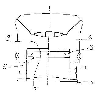
The invention relates
to a self-inking stamp with overshot
inking, comprising a lower section (1),
which may be applied to the surface
to stamp, an inking cushion, arranged
in an exchangeable holder (3), which
may be inserted into a mounting shaft
(8) and a turning mechanism. Said
turning mechanism is for a print plate
support which may be moved back and
forth with simultaneous turning and
which is arranged in the lower section,
between the inking cushion and an
applicator frame (5). The invention
further comprises an operating upper
section (6), which may be displaced
against the force of a spring, relative to
the lower section, whereby the inking
cushion holder on the upper side
thereof is provided with at least one
groove (7), extending in the direction
of displacement, into which a rib (9)
on the upper side of the mounting
shaft positively engages.
L'invention concerne un tampon auto-encreur, à coloration par choc, comprenant une base (1) applicable sur la surface à tamponner, un coussin encreur qui est disposé dans un réceptacle (3) interchangeable par insertion dans un compartiment récepteur (8), et un mécanisme inverseur pour un support de plaque d'impression à déplacement alternatif avec inversion concomitante, disposé dans la base, entre le coussin encreur et un cadre applicateur (5), ainsi qu'un bloc supérieur d'actionnement (6) déplaçable par rapport à la base, à l'encontre de la force exercée par un ressort, caractérisé en ce que le réceptacle à coussin encreur est muni à sa partie supérieure, d'au moins une rainure (7) s'étendant en direction de l'insertion, dans laquelle vient en prise, avec liaison de forme, une nervure (9) prévue à la partie supérieure du compartiment récepteur.
Note: Claims are shown in the official language in which they were submitted.
Note: Descriptions are shown in the official language in which they were submitted.
2024-08-01:As part of the Next Generation Patents (NGP) transition, the Canadian Patents Database (CPD) now contains a more detailed Event History, which replicates the Event Log of our new back-office solution.
Please note that "Inactive:" events refers to events no longer in use in our new back-office solution.
For a clearer understanding of the status of the application/patent presented on this page, the site Disclaimer , as well as the definitions for Patent , Event History , Maintenance Fee and Payment History should be consulted.
| Description | Date |
|---|---|
| Time Limit for Reversal Expired | 2017-04-12 |
| Letter Sent | 2016-04-12 |
| Grant by Issuance | 2008-12-02 |
| Inactive: Cover page published | 2008-12-01 |
| Amendment After Allowance Requirements Determined Compliant | 2008-09-25 |
| Inactive: Office letter | 2008-09-25 |
| Letter Sent | 2008-09-25 |
| Inactive: Final fee received | 2008-04-14 |
| Pre-grant | 2008-04-14 |
| Inactive: Amendment after Allowance Fee Processed | 2008-04-14 |
| Amendment After Allowance (AAA) Received | 2008-04-14 |
| Notice of Allowance is Issued | 2007-10-23 |
| Notice of Allowance is Issued | 2007-10-23 |
| Letter Sent | 2007-10-23 |
| Inactive: Approved for allowance (AFA) | 2007-10-11 |
| Letter Sent | 2006-04-06 |
| Request for Examination Requirements Determined Compliant | 2006-03-16 |
| All Requirements for Examination Determined Compliant | 2006-03-16 |
| Request for Examination Received | 2006-03-16 |
| Letter Sent | 2002-07-18 |
| Inactive: Cover page published | 2002-07-09 |
| Inactive: Notice - National entry - No RFE | 2002-07-05 |
| Application Received - PCT | 2002-04-24 |
| Inactive: Single transfer | 2002-02-19 |
| National Entry Requirements Determined Compliant | 2002-01-10 |
| National Entry Requirements Determined Compliant | 2002-01-10 |
| National Entry Requirements Determined Compliant | 2002-01-10 |
| Application Published (Open to Public Inspection) | 2001-11-15 |
There is no abandonment history.
The last payment was received on 2008-04-09
Note : If the full payment has not been received on or before the date indicated, a further fee may be required which may be one of the following
Patent fees are adjusted on the 1st of January every year. The amounts above are the current amounts if received by December 31 of the current year.
Please refer to the CIPO
Patent Fees
web page to see all current fee amounts.
Note: Records showing the ownership history in alphabetical order.
| Current Owners on Record |
|---|
| TRODAT GMBH |
| Past Owners on Record |
|---|
| PETER ZINDL |
| WOLFGANG PICHLER |

