Note: Descriptions are shown in the official language in which they were submitted.
CA 02378189 2001-12-27
WO 01/01196 PCTIUSOO/17700
MODULAR BITE BLOCK AND SENSOR HOLDER APPARATUS FOR
DENTAL X-RAY PROCEDURES
TECHNICAL FIELD
The present invention is a bite block and sensor holder apparatus for
i0 use during dental x-ray procedures. More particularly, the invention is a
modular bite block and sensor holder assembly, such that a given sensor can
be used with bite blocks for different x-ray procedures. Also, provided is an
improved aiming ring for use in dental x-ray procedures.
BACKGROUND OF THE INVENTION
Dental radiographs are made using x-ray examination units, often
including an x-ray cone or tube positioned proximate the patient and aligned
to
take x-rays of certain teeth. Dental x-ray sensors, including films, charge
coupled devices, phosphor imaging plates or the like, often have a generally
flat or plate-like configuration and standardized dimensions so that the
sensor
can be placed into the oral cavity.
The sensor is placed into the patient's mouth and held in place
proximate to the tooth or teeth to be examined. The x-ray's are directed
through the target teeth and then through the sensor. It has been found that
proper orientation of the sensor is required to eliminate distortions and
improper focus.
To ensure proper orientation of the sensor, sensor carriers with "bite
blocks" have been developed. These devices often have a plate for holding the
sensor and another plate that the patient bites down upon to position the
device
and the carried sensor. A bite block is shown for example, in U.S. Pat. No.
3,473,026.
1
CA 02378189 2001-12-27
WO 01/01196 PCTIUSOO/17700
Different sensors are often used depending upon the area of the mouth
to be examined. This may include for example, endo, posterior, anterior, left,
right, upper and lower bite wings, and the like. Known bite blocks and sensor
holders have been individually designed and manufactured for each different
type of sensor. The dimensions of the sensor and the holder dictate the degree
of secured positioning of the sensor in the holder.
A dental professional may have a large number of x-ray sensors with
varying sizes and shapes, and hence, a similarly large number of sensor
holders. The dental professional is often faced with employing a different
l0 sensor or set of sensors, holders and bite blocks depending upon the
particular
x-ray procedure being employed. At best, it is time consuming to change
between sensors, sensor holders and bite blocks.
A need exists therefore, for a sensor holder/bite block assembly or
apparatus, which will accommodate different sizes and shapes of x-ray
sensors. It has also been found that a need exits for an aiming ring that will
accommodate more than one size or shape of dental x-ray collimator.
SUMMARY OF THE INVENTION
It is an object of the invention to provide a dental x-ray bite block.
It is another object of the invention to provide a bite block having an x-
ray sensor holder.
It is a further object of the invention to provide a bite block and sensor
holder assembly, which can be employed to hold a variety of sensors of
different shapes or sizes.
It is yet another object of the invention to provide such a modular bite
block which will detachably connect to a sensor holder.
These and other objects of the present invention, as well as the
advantages thereof over existing art forms, which will become apparent in
view of the following specification are accomplished by means hereinafter
described and claimed.
2
CA 02378189 2011-11-23
64053-455
In general, a dental bite block and sensor holder
assembly comprises a bite block configured to detachably
affix to a sensor holder. Affixing means are provided
between the bite block and the sensor holder such that the
sensor holder is removably affixed to the bite block.
In one broad aspect there is provided a dental
x-ray positioning device comprising: a bite block and sensor
holder assembly, and means to removably affix said sensor
holder to said bite block, wherein said means to removably
affix said sensor holder to said bite block comprises a
complex profile tab carried by said one of said bite block
or said sensor holder, and an at least partially
corresponding slot carried by the other of said bite block
or said sensor holder.
In another broad aspect there is provided a method
of assembling a bite block and sensor holder assembly for
taking a dental x-ray comprising the steps of: (i)
inserting a complex profile tab carried by said sensor
holder into a receiving slot carried by said bite block to
removably affix said sensor holder to said bite block; and
(ii) positioning a dental x-ray sensor into said sensor
holder either before or after step (i).
In another broad aspect there is provided a dental
x-ray positioning device kit comprising a bite block of
modular design, a sensor holder assembly and means to
removably affix said sensor holder to said bite block of
modular design, wherein said bite block (i) provides an area
that is clamped between a patient's teeth; and (ii) is
configured for use in a specific x-ray procedure by being
shaped so that a specific x-ray image may be taken when the
area is clamped between a patient's teeth.
3
CA 02378189 2011-11-23
64053-455
Preferred forms of the subject dental bite block
and sensor holder assembly are shown by way of example in
the accompanying drawings, and are deemed sufficient to
effect a full disclosure of the invention. The exemplary
assembly is described in detail without attempting to show
all of the various forms and modifications in which the
invention might be embodied; the invention being measured by
the appended claims and not by the details of the
specification.
3a
CA 02378189 2011-11-23
64053-455
BRIEF DESCRIPTION OF THE DRAWINGS
Fig. I is a perspective, exploded view of a bite block and sensor holder
assembly; embodying the concepts of the present invention;
Fig. 2 is a perspective, exploded view of an alternative embodiment of
a bite block and sensor holder assembly, also embodying the concepts of the
present invention;
Fig. 3 is a perspective, exploded view of another alternative
embodiment of a bite block and sensor holder assembly, also embodying the
concepts of the present invention;
Fig. 4 is an alternative embodiment of the sensor holder portion of the
invention as depicted in Fig. 1;
Fig. 5 is an alternative embodiment of an aiming ring and bite block
assembly according to the invention; and
Fig. 6 is an alternative embodiment of an aiming ring and bite block
assembly according to the invention.
PREFERRED EMBODIMENTS FOR CARRYING OUT THE INVENTION
An x-ray sensor-positioning device according to the invention is
generally designated by the number 10 on the attached drawings. Assembly
3b
CA 02378189 2008-10-30
64053-455
is preferably configured to have a conventional dental x-ray guide arm 12.
An exemplary guide ann and its use with a bite block for taking a dental x-ray
is shown in U.S. Pat. No. 3,473,026. As shown in Figs. 1-3, guide arm 12
may be configured to be affixable to an x-ray tube collimator-positioning ring
5 13 in a conventional manner. Such a ring is also shown for example, in U.S.
Pat. No. 3,473,026, and, US Des. 237,016.
Aiming ring 13a, Fig. 5, shows a plurality of regularly spaced,
10 opposing steps 13b for receiving and registering a collimator (not shown).
One set of such steps is known in the art (see for example, US Des. 237,016).
The present invention employs two sets of steps 13b in order to allow
registration of more than one size of collimator. Although it is preferred to
"concentrically" arrange one set of steps 13b within another, sets of steps
13b
can be offset if desired. Grooves 14 can be provided in the exterior diameter
of aiming ring 13a, such that an x-ray tubehead (not shown) can be aligned to
wholly encompass whatever x-ray sensor is held by positioning device 10.
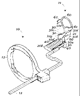
A bite block and sensor holder assembly 11 is provided as part of
device 10, and includes a bite block 20 and a sensor holder 21 (Fig. 1). Bite
block 20 is generally configured for use in a specific x-ray procedure. For
example, bite block 20 in Fig. 1 is of a configuration useful for an endo x-
ray.
Bite block 20a (Fig. 2) is suited for use in taking a bitewing x-ray, and Fig.
3
shows a bite block 20b useful in taking an anterior or posterior x-ray image.
Each bite block 20, 20a and 20b serve the same function, that is providing an
area that is clamped between a patient's teeth. Given the requirements of a
specific x-ray however, different shapes of bite blocks are required. The
invention will be exemplified herein with reference to bite block 20 of Fig. 1
for purposes of this discussion (unless otherwise noted), it being understood
that the invention is equally useful with bite blocks 20a, 20b or indeed, any
conventional bite block shape or size without limitation.
4
CA 02378189 2001-12-27
WO 01/01196 PCTIUS00/17700
There is removably attached to bite block 20 the sensor holder 21. It is
likely that a dental professional will use one size and shape of sensor, be it
x-
ray film, CCD or phosphor plate technology for different x-rays (endo,
anterior, posterior, bitewing or the like). Before the present invention, it
would be standard practice for the dental professional to have a variety of
bite
block/sensor holders integrally formed together. According to the present
invention, the sensor holder 21 and the bite block 20 are not integrally
formed
but rather detachably affixed. Further, the structure to attach a sensor
holder
21 to a bite block 20 (which will be discussed and exemplified below), is the
same no matter what the shape of the given bite block 20, 20a or 20b. In this
manner, it will be appreciated that a single sensor holder can be used to
attach
to a different bite block 20, 20a or 20b. This is termed a "modular" design
for
purposes of this discussion. It will also be appreciated that a bite block may
be used with different sizes and shapes of sensor holders. Again, the
invention
will be exemplified herein with respect to a single sensor holder 21.
To be detachably affixed to a bite block 20, sensor holder 21 must be
provided with attachment means that correspond to attachment means carried
by the bite block 20. By providing bite block 20 with the same attachment
means as bite blocks having other shapes, such as bite blocks 20a and 20b, the
same sensor 21 can be detachably affixed to any bite block 20, 20a or 20b, or
indeed, any bite block carrying the same attachment means.
Any attachment means between sensor holder 21 and bite block 20 is
within the scope of the invention, the only criteria being that the two
components be held securely with respect to each other and that they be
removable. Again, this aspect is termed being "modular" in design. A
preferred attachment means is a complex profile or tab 30 carried by sensor
holder 21 and an at least partially corresponding slot 31 carried by bite
block
20. It is understood that bite block 20 could easily be configured to carry
complex profile 30 and that sensor holder 21 could carry slot 31 and still be
within the scope of the invention. The invention will be exemplified with
sensor 21 carrying complex profile 30.
5
CA 02378189 2001-12-27
WO 01/01196 PCT/USOO/17700
By "complex profile" it is meant a plurality of surfaces, such as
surfaces 30a-30f (Fig. 1) each at some angle to at least one other. Complex
profile tabs 30 and corresponding slots 31 can also be round and still fall
within the scope of the definition of "complex profile". Surfaces 30a-f of
complex profile 30 need not necessarily be linear, but may be curvilinear,
such
as surface 30g, or even round. By "slot" it is meant some surface such as
surface 31a configured to receive at least one surface of complex profile 30
such as surface 30c.
Preferably, slot 31 is configured to receive complex profile 30 in such
a manner that a plurality of surfaces 30a-f physically engage or touch slot 31
and at least some other portion of bite block 20. By properly configuring the
actual dimensions of these components, sensor 21 can be held securely to bite
block 20. The fit between complex profile 30 and slot 31 may also be a
friction fit. It will be appreciated that to secure sensor 21 to bite block
20,
complex profile 30 is received within slot 31. To detach or remove sensor 21
from bite block 20, it is merely necessary to slide complex profile 30 from
slot
31.
An alternative embodiment of slot 31 is shown by way of example in
Fig. 3 as slot 40. Slot 40 is itself also of a "complex profile" substantially
corresponding in shape and dimension to the shape and dimension of complex
profile 30.
It is also to be appreciated that complex profile 30 may be configured
to have a plurality of arms 50 and 51, each carrying its own complex profile
30. In the embodiment of the invention depicted in the drawings, sensor 21
has two arms 50 and 51, it being understood that any number of arms is within
the scope of the invention. It is also to be appreciated that any means of
detachably affixing sensor 21 to bite block 20 is within the scope of the
invention. This may include, bolts, screws, nuts, locking mechanisms, or the
like without limitation, all of which are within the scope of the invention
and
the term "modular."
6
CA 02378189 2001-12-27
WO 01/01196 PCTIUSOO/17700
Sensor holder 21 will be configured to receive one or more sensors.
For example, in the sensor 21 depicted in Figs. 1-3, a back support 60 and
clip
arms 61, 62 are employed. A sensor (not shown) can be secured within sensor
21. Because any sensor holder of any configuration is within the scope of the
invention, and because such sensor holders are conventional in the art, no
specific sensor holder, or bit block, is necessarily a limitation of the
present
invention.
For example, Fig. 4 depicts an alternative embodiment of a sensor
holder 21a. Sensor holder 21a is configured with a back support 60 similar to
back support 60 of sensor 21. However, in place of clip arms 61 and 62 of
sensor 21, sensor 21a is provided with upper clip arm 70, generally opposing a
lower clip arm 71. A conventional sensor (again, not show) is supported
between clip arms 70, 71 and back support 60. Otherwise, sensor 21a is
substantially similar in its modular design to sensor 21.
Fig. 6 shows an alternative embodiment of a bitewing block 80.
Bitewing 80 is provided with a groove 81 on the bite surface 82 to help the
user in positioning a sensor (not shown) held by block 80. Groove 81 helps to
register wuch such a sensor. It will also be appreciated that block 80 is of
an
overall thin design, allowing for greater patient comfort as compared to prior
bite blocks.
Based upon the foregoing disclosure, it should now be apparent that
the use of the modular bite block and sensor holder assembly described herein
will carry out the objects set forth hereinabove. It is, therefore, to be
understood that any variations evident fall within the scope of the claimed
invention and thus, the selection of specific component elements or parts can
be determined without departing from the spirit of the invention herein
disclosed and described. Thus, the scope of the invention shall include all
modifications and variations that may fall within the scope of the attached
claims.
7