Note: Descriptions are shown in the official language in which they were submitted.
CA 02378279 2002-04-15
POLE-MOUNTED LIGHTING SYSTEM
BACKGRODND OF THS INVENTION
Field of the Invention
The present invention relates to pale-mounted lighting
systems, and in particular, to means and methods for mounting on
F>oles various structures related to elevated lighting fixtures
!:or large area lighting.
B. Background of the Invention
There are many examples of pole-mounted large area lighting
systems. They include sports field lighting; such as softball,
baseball, football, soccer fields and the like. It also includes
tennis court lighting, and playground lighting; and could also
include such things as parking lat lighting.
The most conventional way of elevating lighting fixtures to
enable large scale lighting is to install poles in the ground and
then secure structures to the poles to facilitate such lighting.
- 1 -
'' CA 02378279 2002-04-15
It is usually desirable to elevate the lighting fixtures as high
as economically practical. The higher the light pole the
costlier. Therefore there is usually a practical limit on the
height of poles which is directly related to cost. Multiple
fixtures normally are positioned on some sort of a cross-arm
which is then secured to the pole» Multiple cross-arms on each
pole are possible. Other structures, such as electrical boxes
containing ballasts, circuit: breakers, fuses, switches, and other
electrical components are also commonly suspended along the
length of the pole. Such components can either be associated
with the cross-arms, or be spaced apart from and usually lower on
th.e pole.
While it may appear to be elementary to accomplish lighting
systems of this type, a number of different design criteria and
considerations are involved.. For example, it is not trivial to
secure structures of substantial size and weight to a pole. The
structures must be mounted securely and in a durable manner for
long term use. The mounting structure must also be strong to
support cross-arms, fixtures, and such things as ballast boxes;
particularly in light of wind loads that exist on outdoors
s~~stems .
Another set of considerations involves cost of manufacturing
arid installation. As with most commercial goods, the cost of
making the goods impacts significantly on the cost of the goods
to consumers. There is narrnally high incentive to be able to
present the lowest price t:o consumers;. therefore there is high
incentive to devise systems which are as inexpensive as possible
- 2 -
CA 02378279 2002-04-15
to manufacture. This impacts on design and the type of materials
utilized.
Another consideration is the shipping of these components
from factory to installation site. Limits of size and weight
come into play. For example, shipment via semi-trailer limits
th.e maximum dimensions of pieces.
Still further, there is generally a high incentive to offer
goods to consumers that are easy to install while meeting
performance requirements for the 'types of components.
Still further, it is usually desirable that the goods be
flexible and customizable to varying installation situations. In
other words, it is most times advantageous to have, for example,
mounting systems that are generally universal with the ability to
work for different mounting situations such as, for example,
different heights, diameter, and types of poles.
In the field of the present invention, these considerations
a~>ply. There are practical limitations on the number of light
fj.xtures that can be suspended from each pole. It depends on
f~~ctors such as the type of pole (examples are wood, steel,
concrete), the height of the pole, and the lighting requirements
a:~sociated with that pole. As a general rule it is most cost-
ei=fective to be able to elevate a maximum number of fixtures from
each pole, as the poles and their installation comprise a
s~Lgnificant amount of the cost for lighting systems.
In the same sense, because structures such as cross-arms,
l:Lghting fixtures, and ballast boxes are substantial in size, and
nE~ed to be installed at elevated positions from the ground, it is
- 3. -
CA 02378279 2002-04-15
. . ,-...
highly desirable that the mounting procedures be as simple and
quick as possible. With this is t:he need for flexible, almost
universal, mounting components that can be adapted easily by the
installers for different situations.
Many consumers also take into consideration how a certain
system visually looks from an attractiveness standpoint, in
cooperation with its functionality.
There are currently many ways of suspending lighting
fixtures and related structures on poles for accommodating large
scale lighting. It is submitted, however, that there is room for
improvement in this field of art. Two specific examples are set
forth below.
As previously mentioned, it is highly desirable to suspend
as many lighting fixtures per pole as possible, in most
situations. Currently a conventional way to attach fixtures to a
pole is to mount one or more cross-arms to the pole, each cross-
arm bearing multiple light fixtures and having separate pole-
attaching hardware. One time saver that exists in the art is to
connect the light fixtures 1.o the cross-arm before raising the
entire cross-arm assembly to its position at the top of the pole.
However, if more than one :bar of :Lights is required, significant
time and effort must be utilized to position and then secure the
first cross-arm, then the second, then any others.
Another example involvE~s ballast boxes. They are normally
secured by brackets that surround the pole and connect to the top
and bottom of the ballast box. However, when installing and
cinching the box against thf~ pole, certain problems can exist. -
- 4 -
CA 02378279 2002-04-15
~. ; --.
t
~ .
There are times when rotational or other forces can deform or
even permanently warp the ballast box. This can significantly
affect the ballast box in, for example, causing misalignment of
any door on the box so that it does not fit securely, which in
turn can lead to water leakage or other detrimental and
potentially serious problems for the lighting system. For
example, if the ballast box is not accurately aligned along the
pale, when tightened, deformation or warping can occur. Another
instance is if the pole is crooked. A still further example
involves cases where wood poles are used and mounting brackets
s3.nk into the wood at different rates. Knots or other
dj.scontinuities in poles can also cause problems. It is to be
understood that other situations can also cause problems
resulting in the risk of deformation or warpage.
It is therefore the primary object of the present invention
to provide a~pole-mounted lighting system which improves over
some of the problems and deficiencies in the art.
Another object of the ;present invention is to provide a
pole-mounted lighting system which securely and durably mounts
sitructures to poles, but limits potentially damaging stresses on
the structures when being mounted.
Another object of the present invention is to provide a
pole-mounted lighting system which is easy to mount to the pole
~i:n a minimum amount of time and steps,
A still further object of the present invention is to
provide a pole-mounted lighting system which is flexible in the
types of structure and poie~s with which it can be used.
CA 02378279 2002-04-15
Another object of the present invention is to provide a
pole-mounted lighting system which deters or avoids mounting
problems related to misalignment of structures with respect to
the poles, crooked poles, poles having surface irregularities,
and poles such as wood poles which are crooked or have varying
wood density, knots, or other discontinuities.
Another object of the present invention is to provide a
pole-mounted lighting system which allows a significant amount of
neaeded structure, for example, lighting fixtures, ballasts, or
other electrical components, to be mounted on an existing pole.
Another object of the present invention is to provide a
light-mounted lighting system which allows for easy electrical
interconnection of electrical components, even if they are spaced
apart from one another on the pole.
These and other objects, features, and advantages of the
present invention will become more apparent with reference to the
a<:companying specification and claims.
Si~ARY OF THE INVENTION
The pole-mounted lighting system of the present invention
includes an attachment system for structures, such as cross-arm
assemblies and ballast boxes, to a pole. The cross-arm
assemblies comprise either two or more cross-arms rigidly secured
together, where the entire collection of cross-arms forms an
integral structure that can then be mounted to a pole, or a
cross-arm and ballast combination which can in one step be
mounted to a pole.
- f> -
CA 02378279 2002-04-15
,,
A ballast box, containing multiple ballasts and other
electrical components for a plurality of light fixtures, can be
remotely positioned along the pole from the light fixtures but
easily and quickly installed to the pole.
An aspect of the invention includes mounting components for
these structures which can be customized to securely and easily
mount the structures to a wide variety of pole types, shapes, and
sizes. Another aspect of the invention involves mounting
components which assist in keeping the structure centered on the
pole without stress that could detrimentally deform the structure
when tightened to the pole..
~F~IEF DESCRIPTION OF THE DRAWINGS
Fig. 1 is a perspective view of a light pole, cross-arm
assembly, light fixtures, and remotely positioned ballast box,
according to one embodiment of the present invention.
Fig. 2 is an enlarged perspective view of the cross-arm
assembly of Fig. 1 showing mounting brackets in exploded fashion,
the light pole in ghost lines, and an optional third cross-arm in
ghost lines.
Fig. 3 is an enlarged sectional view taken along line 3-3 of
F~Lg. 2.
Fig. 4 is an enlarged partial sectional view taken along
line 4-4 of Fig. 2.
Fig. 5 is an isolated elevational view taken along line 5-5
o:E Fig . 4 .
_ i,
CA 02378279 2002-04-15
Fig. 6 is an enlarged perspective view of the ballast box
~~hown at line 6-6 of Fig. 1, from a generally opposite direction
from Fig.~l, showing the mounting components in exploded fashion
a.nd the light pole in ghost lines.
Fig. 7 is an enlarged sectional view taken along line 7-7 of
F'ig. 6 but showing the pole in solid lines.
Fig. 8 is an enlarged partial elevational and sectional view
taken along line 8-8 of Fig. 6 but showing the pole in solid
lines.
Fig. 9 is an isolated and still further enlarged partial
elevational and sectional view taken along line 9-9 of Fig. 7.
Fig. 10 is an exploded perspective view of an alternative
embodiment for the mounting brackets of Fig. 6.
Fig. 11 is an enlarged elevational view taken along line 11-
11 of Fig. 10.
Fig. 12 is a sectional. view taken along line 12-12 of Fig.
11.
Fig. 13 is a still further embodiment of the mounting
brackets for Fig. 6 shown in perspective exploded form.
Fig. 14 is an enlarged partial elevational view taken along
line 14-14 of Fig. 13.
Fig. 15 is a sectional view taken along line 15-15 of Fig.
1 ~4 .
Fig. 16 is an enlarged sectional view taken along line 16-16
o:E Fig. 13.
_ g _
CA 02378279 2002-04-15
-... r~~
;;
Fig. 17 is a still further enlarged sectional view taken
along line 17-17 of Fig. lfi..
Fig. 18 is a perspective view of a cross-arm and ballast box
combination with mounting brackets for a light pole shown in
exploded fashion.
DETAILED DESCRIPTION OF PREFERRED EMBODIMENT
A. Overview
To assist in an understanding of the invention, a detailed
description of preferred embodiments wil3. now be set forth. It
is to be understood that these embodiments are examples of some
farms the invention can take, but do not define all the forms the
invention can take.
B. General Configuration -- Fig. 1
This description will refer to the drawing figures, and will
reference certain parts and locations in the figures by reference
numerals or characters. The same reference numerals or
characters will be used to .identify the same or similar parts and
locations in all of the figures unless otherwise explained.
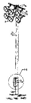
Fig. 1 illustrates in ;perspective form one preferred
embodiment of the invention (which will be generally designated
a~; embodiment 10) on a light pole 12.
It is to be understood for purposes of this description that
light pole 12 consists of a pole several tens of feet tall and
made of wood (solid concrete would be another example). It is to
be understood that the invention could be used with a variety of
tropes of poles, including hollow metal or concrete poles, and '
- 9 -
CA 02378279 2002-04-15
,.-~ r.~,.,
even tapered poles. The pale 12 3.s secured in the ground by
methods known in the art.
In Fig. 1, what will be called a cross-arm assembly 16 is
mounted at the top of pole 1.2 and what will be called a remote
ballast box 18 is mounted near the bottom of pole 12.
Light fixtures 20 are positioned on cross-arm assembly 16.
In this case six such fixtures 20 exist. On each bar, in this
embodiment, a fixture 20 is mounted on opposite sides of the bar,
and a fixture 20 is mounted in between. As is shown in Fig. 1,
an electrical conduit 22 extends from ballast box 18 up to cross-
arm assembly 16 for purposes of providing electrical power and
control wires to fixtures 20. It is to be understood that such
wiring could be alternatively routed inside of pale 12, if hollow
metal or concrete, for example, and that electrical power is
received by ballast box from an electrical power source (not
shown).
Fig. 1 also illustrates that conventionally ballast box 18
hays a door 24 which can be opened for access to components such
as. ballasts, fuses, circuit breakers, switches, etc. Such a door
29: needs to seal securely to box 18 to prevent water leakage and
protect the components inside box 18.
C. Cross-arm Assembly -- Figs. 2-5
Fig. 2 shows in more detail the exact structure of cross-arm
a:~sembly 16. Top cross-ar°m 26 and bottom cross-arm 28 are
parallel and spaced apart by interconnecting member 30. Assembly
1(i is unitary and basically "I" shaped. Each component 26, 28,
and 30 is at least partially hollow to allow interior wiring to
- 1(7 -
CA 02378279 2002-04-15
fixtures 20. It is to be understood that the underside of cross-
arms 26 and 28 have spaced apart openings and apertures which
allow fixtures 20 to be bolted onto the underside of arms 26 and
28.
As shown in Fig. 2, arms 26 and 28 are two inches in height
and three inches in depth. Component 30 is four inches wide by
three inches in depth. Other sizes are possible. The length of
arms 26 and 28 can be made to desired lengths, within practical
constraints. For example, the wind load on fixtures such as
fixtures 20 limits the number of fixtures and therefore the
maximum length of arms 26 and 28. Fig. 2 shows that additional
cross-arms (such as cross-arm 32 in ghost lines) can be added by
also adding an appropriate interconnecting member (see member 34
ir,~ ghost lines in Fig. 2). It is preferred that assembly 16
consist either of two or three cross-arms because any more cross-
a~~ms would make it difficult to ship on standard-sized trucks.
It; is further to be understood that the number of fixtures 20
that can be suspended from each cross-arm assembly 16 is
selectable. Fig. 1 shows s:ix such fixtures as an example only.
By extending the length of cross-arm, up to, for example, seven
fj_xtures per cross-arm are :reasonable. Therefore, with three
cz~oss-arms, assembly 16 could utilize up to twenty-one or so
f9_xtures 20.
Cross-arm assembly 16 of Fig. 2 has several other features.
A short arm 36 extends from cross-arms 26 and 28 (and 32 if used)
orthogonally (mutually perpendicular) with respect to each cross-
arm and interconnecting member at their junction. Each arm 36 '
- 1:1 -
CA 02378279 2002-04-15
has on its bottom surface the appropriate openings or structures
to mount a fixture 20, as shown in Fig. 1. Without this arm 36,
it would not be possible to mount fixture 20 in that manner at
the junction of cross-arm and interconnecting member, and which
in this case is generally at: the center of the cross-arm.
Cover plates 38 in Fig. 2 sealingly close off openings in
interconnecting member 30 which allow access to the interior
wiring of assembly 16. "L" brackE~ts 40, on top and bottom cross-
ar~m 26 and 28, and on opposite sides of interconnecting member
30, have apertures 42 which cooperate with what will be referred
to as the mounting brackets 44 of Fig. 2, to secure cross-arm
assembly 16 to pole 12. Note that different sets of holes 42
exist to assist in mounting for different sized poles.
In Fig. 2 mounting brackets 44 consist of threaded rods 46
which are securable through apertures 42 in "L" brackets 40, and
"W" brackets 48 which cooperate with threaded rod 50 and threaded
rods 46 to surround and there allow tightening of assembly 16
against pole 12 by threadably securing the nuts and washers (as
shown) onto threaded rods 4fi and 50. These arrangements allow
the secure and strong attachment of assembly 16 to pole 12 but
with a high degree of adjustability and flexibility for different
sizes of pole 12. Other arrangements are possible.
Fig. 2 also shows that a wiring harness 52 can be utilized
to extend into assembly 16 to allow pre-wired, pre-attachment of
fixtures 20 to cross-arm assembly 16 prior to raising it up on
pole 12 for securement in place. The work required to wire up
fixtures 20 can all be done on the ground or at a factory which
_ 1~> _
CA 02378279 2002-04-15
'~'~ ~ L
a
eliminates such critical and time consuming work which would
otherwise have to be done at the 'top of light pole 12.
In the preferred embodiment, interconnecting member 30 is
welded to top and bottom cross-arms 26 and 28, which are made of
steel or similar material. Other ways of securing these
components into an integral unit are possible.
Figs. 3 and 4 depict cross-arm assembly 16 as secured to
light pole 12. As can be understood, by selectively tightening
nets 54 on the threaded rods 46 and 50, serves to bring "W"
brackets 48 and cross-arm assembly 16 into abutment with pole 12,
and cinch or clamp assembly 16 to pole 12. By watching "W"
brackets 48, the installer can accurately turn nuts 54 upon
threaded rods 46 and 50 to .accurately position "W" brackets 48 so
that the whole mounting bracket 44 (including "L" brackets 42,
threaded rods 46 and 50, and "W" brackets 48) is centered and in
that condition offers the best clamping action.
Fig. 4 illustrates that utilization of mounting brackets 44
a1: both the top and bottom of assembly 16 will hold the entire
assembly 16, with fixtures 20 mounted thereon, in place at the
top of pole 12. Fig. 4 also illustrates wiring harness 52 with a
quick connect connector 56 which can be positioned inside
a:~sembly 16 and allows the wiring going to fixtures 20 to be
quickly connected up. The opposite end of wiring harness 52 can
e:Ktend out of the bottom c~f cross-arm assembly 16 through conduit
2:z and be cut to length once assembly 16 is in place to match up
with the position of a remote ballast box. Note in Fig. 4 that
t)ze wiring bundle or harness 52 Extends through conduit 22 (which
-- 13 -
CA 02378279 2002-04-15
,.--..
j
is connected to assembly 16 at connection 23) up into.component
30. A J-hook 25 is secured by welding or otherwise to the
interior of 30. A kellum-grip 27 surrounds harness 52 and is
used to hang harness 52 fram hook 25 so that plug 56 can then be
easily assessable through the openings which are covered by cover
plates 38.
Fig. 5 illustrates a cover plate 38. A top ear 58 is bolted
to interconnecting member 30. A bottom ear 60 has a C-shaped
cutout 62 which allows cover 38 to be swung away around the pivot
axis of bolt 64, for access into the interior of assembly 16.
Comer 38 can then be easily swung back into position and secured
into place by bolt 66. It i_s to be understood that this
arrangement eliminates the need to completely remove cover 38 and
also utilizes gravity to an extent to swing cover 38 back into
position when released. A gasket or O-ring can be placed between
cover 38 and member 30 to seal the opening.
D. Mounting System Figs. 6-9
Figs. 6-9 illustrate an embodiment for a mounting system for
seacuring structures to a pole 12. In particular,, this embodiment
depicts the mounting of a ballast box 18. The system can be
of>ed, however, for mounting other structures or components.
To illustrate some of the advantages of the mounting system
oiE Figs. 6-9, the previously discussed problems with mounting
ballast boxes will be referred to. Ballast boxes like box l8 are
gE~nerally made of relatively thin metal. If such a box were to
bE~ connected to pole 12 by mounting components such as those
shown in Fig. 44, there is the risk that when tightening down
- 14 -
CA 02378279 2002-04-15
i-~.~ ,.....
nuts 54, uneven pressure or stress will be created at one corner
or portion of ballast box 18. This in turn could cause the
warping of box 18. If the warping is severe enough, it could
affect the performance of the box 18; for example, the door 24
may not close, water leakage may occur through the door or a seam
in. the box, or other environmental conditions may adversely
affect box i8 or the contents of box 18. As previously
discussed, such warpage can be caused by the box being originally
mi.saligned or mis-centered on the pole before tightening of the
mounting hardware.
Still further, mounting components such as brackets 44 of
Fi.g. 2, are time consuming in their installation because of all
the nuts 54 that must be secured, and the skill required to
position and center the structure while being mounted.
In Fig. 6 there is shown a mounting system which includes
top strap 70, bottom strap 72, fixed connection bracket 74, and
pivoting connection bracket 76,
Fixed connection bracket 74 is rigidly secured to the top
beck side of ballast box 1.8. It is C-shaped in cross section
(with its open side facing out), has apertures 78 at opposite
side ends, and V-shaped cutouts or recesses 80 along its center
to facilitate reception arid centering of pole 12 in bracket 74.
C--shaped receptors 82 are attachable by bolts 84 to opposite ends
oj° bracket 74. Adjustment connectors 86 are fixable to opposite
ends of top strap 70 by balts 88. Adjustment connectors 86
include threaded ends 90 which can be inserted into apertures 92
ojF C-shaped receptors 82. The corresponding nuts 94 for threaded
1~~ _
i
CA 02378279 2002-04-15
ends 90 are then turned down to tighten top strap 70 and the top
of ballast box 18 to pole 12.
It is to be understood that top strap 70 can be initially of
a :Longer length and then cut to a length which approximates that
needed to surround the portion of pole 12 selected to clamp
ballast box 18 to pole 12. It can then be attached to adjustment
connectors 86 by bolts 88 through selected holes in strap 70.
Adjustment connectors 86 can be used for the final and fine
adjustment and clamping action of box 18 to pole 12. Essentially
this arrangement would only require the tightening down of nuts
94 once box is positioned on pole 12. All other connections of
the brackets of Fig. 6 could be previously made. The V-shaped
cut outs 80 of bracket 74 help center the pole and then nuts 94,
ca.n be tightened to provide the clamping action. Strap 70 is
made preferably of stainless steel and serves to grip pole 12 and
clamp the top of box 18 in place.
The arrangement of bottom strap 72 is similar to top strap
7C1, with the following differences. To eliminate as much as
possible the potential for warpage of box 18, pivoting connection
bracket 76 is connected to box 18 by bolt 96 and pivot bracket
9E3. Resilient pads 100 and 102 (in the preferred embodiment made
oi= medium density foam rubber) are attached to ballast box 18 on
opposite lateral sides of pivot bracket 98. The opposite sides
o:E bracket 74 therefore extend across pads 100 and 102.
This arrangement functions as follows. In normal-
installation, the length of straps 70 and 72 are cut to as close
t~~ size as is possible for the particular pole diameter at the
- 1~6 -
CA 02378279 2002-04-15
-.
selected location of installation of ballast box 18. Adjustment
connectors 86 are bolted by bolts 88 to the free ends of straps
70 and 72. C-shaped receptors 82 are bolted by bolts 84 to the
opposite ends of bracket 74. C-shaped receptors 82 are connected
by bolts 84 to the opposite ends of pivoting connection bracket
76, and bracket 76 is pivotably connected to pivot bracket 98.
Ballast box 18 is brought to pole 12 and roughly positioned at
th.e location of intended installation. V-shaped recesses 80 in
brackets 74 and 76 assist in this positioning. Threaded ends 90
of: adjustment connectors 86 are then inserted into apertures 92
iri C-shaped receptors 82 in bracket 74, and nuts 94 are tightened
down to pull the top of ballast box 18 to pole 12. The bottom
pivoting bracket ?6 and pads 100 and 102 on box 18 cooperate to
deter deformation or warpage of box 18 as follows. Pads 100 and
1t12 extend from the back of box 18 and hold bracket 76 in
basically a parallel orientation with respect to the back of box
18 when it is being installed. If any rotation or misalignment,
or any force or structure attempts to pivot bracket 76 away from
this prefer-red position, pads 100, 102 will resist the same and
urge bracket to remain parallel. One or the other of pads 100 or
102 may come into contact with one side of pivoting connection
bracket 76 and will resiliently urge bracket 76 back to a
parallel position (meaning a generally parallel orientation to
the back of box 18). This will then present bracket 76 in this
intended position when threaded ends 90 of adjustment connectors
86 on strap 72 are inserted into C-shaped receptors 82 on
pivoting bracket 76. This positioning of bracket 76 assists
- 17 -
CA 02378279 2002-04-15
k~racket 76 in transferring stress to the center of box 18 (as
opposed to its bottom side edges) when nuts 94 are tightened down
on threaded portions 90 of adjustment connectors 86 of bottom
strap 72. This, avoids placement of tension on the bottom
corners of box 18, which would cause tension on box 18. Thus, it
will then deter any deformation or permanent warping of box 18
during and after box 18 is all tightened down to pole 12. It
will also tend to keep box 18 centered. Again, the clamping of
the bottom of box 18 with bottom strap 72 requires a tightening
of only two nuts 94 which is quick, easy, and also deters tension
on the corners of box 18. Alternative ways of keeping bracket 72
resiliently positioned parallel are possible. An examp3e would
be spring clips between the ends of bracket 72 and box 18.
Figs. 7 and 8 show botaom strap 72 and pivoting connection
bracket 76 in an installed position. It can be seen that
adjustment connectors 86 allow for a range of tightening
adjustment by virtue of their threaded length which exceeds that
need to initially position nuts 94 on threaded ends 90. Fig. 7
also illustrates the centering nature of pole 12 in V-shaped cut
outs 80 and how the centered (parallel) bracket 72 concentrates
stress at the center back ~f box 18.
Fig. 8 shows in more detail the connection of C-shaped
receptors 82 to pivoting connection bracket 76, and also the
configuration of adjustment: connectors 86 and bottom strap 72.
Fig. 9 illustrates in more detail the structure of pivot
bracket 98 and its connection to pivoting connecting brackets 76.
- 18 -
CA 02378279 2002-04-15
t
E. Alternate Mounting System Figs, 10-12
By referring to Figs. 10-12, an alternative embodiment of a
mounting system for that shown in Figs. 6-9 is illustrated. It
is similar to that shown in Figs. 6-9 except as follows. Strap
106 has tear-drop shaped or corn kernel shaped apertures 108 in
two rows along its length (instead of the two rows of square
holes in straps 70 and 72 of Fig. 6). Note that the two rows of
apertures can extend the length of strap 106 (as indicated by
dashed lines). As shown in Fig. 11, a smaller diameter portion
130 of each aperture 108 expands to a larger diameter portion 112
to make the tear-drop shape. It is to be understood that the
smaller diameter portions 1:10 point towards the ends of strap
iCl6. Thus, the apertures 108 are mirror images of one another at
the opposite ends of strap :106.
In direct comparison, ;similar tear-drop shape apertures 114
e~!:ist in adjustment connectors 86 but have the smaller portions
(Like portions 110) point towards the portions 110 of apertures
1C)8 of strap 106. Two headed pins 116 having a large flat head
11.8 of a diameter greater than any portion of apertures 108 or
17.4, and a small or tapered head 120, having a diameter which can
pass through large portion 112 of apertures 108 and 114 but will
not pass through small portions 110 of apertures 108 and 114, are
used to quickly connect the opposite ends of straps 106 to
adjustment connectors 86.
It is to be understood that like previously described, strap
106 is first cut to approximate length for the pole diameter at
the installation location. C-shaped receptors 92, having been
1.9
CA 02378279 2002-04-15
previously connected to bracket 74, for example, and bracket 74
being connected to a structure (far example, ballast box, cross-
arm assembly, etc.), await connection of strap 106.
This can be done by either cannecting adjustment connections
86 to the ends of strap 106 and then inserting and securing
threaded ends 90 of connections 86 into C-shaped receptors 82, or
visa versa. In either case, Figs. 11 and 12 show that the ends
of strap 106 would be inserted between sides of adjustment
connections 86 (which in original condition are sprung open).
Th.e large portions of apertures 114 in connections 86 are aligned
with the large portions of apertures 108 in strap 106. The
s~rualler tapered heads 120 of pins 116 are inserted thxough the
aligned large portions of the apertures. When longitudinal
ts~nsion is applied pulling the ends of strap 106 oppositely from
connections 86 the smaller portions of apertures 108 and 114 be
pulled to the pin. This essentially shearing action will
cooperate with the caroming action of tapered heads 120 to close
down the sides of connections 86 to sandwich the ends of strap
106 as well as to effectively lock pins 1.16 in place, and lock
strap 106 to connections 86. Strap 106 in the preferred
embodiment is only thirty-thousandths of an inch thick. This
connection of strap 106 ends to connections 86 capture the thin
si~rap ends so they do not tear.
Therefore, shown in Figs. 11 and 12, by first appropriately
aligning selected apertures 108 and 114 and inserting small heads
120 of two headed pins 116 through corresponding large ends 110
o:E apertures 108 and 114 of strap 106 and adjustment connector 86
- 20 -
CA 02378279 2002-04-15
,.
~l
(at either end of strap 106), the strap 106 and adjustment
connectors 86 are then pulled in opposite directions so that pin
116 is captured in the small portions of apertures 110 and can
not be removed laterally. Nuts 99: can then be turned down to
finish the tightening of the mounting system.
The embodiment of Figs. 10-12 can be used with either fixed
connection bracket 74 or pivoting connection bracket 76.
F. Alternative Mounting System Figs. 13-17
A still further alternative mounting system is shown at
Figs. 13-17. It essentially functions similarly to those shown
in Figs. 6-9 and Figs. 10-12 except as follows. In this
embodiment strap 122 has a first piece 124 and a second piece
126. Apertures 128, in one row, are contained in embossments
130A in piece 124 and embossments 130B in piece 126 of strap 122
(a.s better shown in Figs. 15 and 16). These embossments 130A and
lf~OB include cavities 123A and 1238 on the back of strap 122 and
raised portions 125A and 125B on the front of strap i22; with
apertures 128 centered therein.
It is to be understood, as shown in Figs. 15 and 16 that
embossments 130A are sized to be .larger then embossments 130B so
that raised portions 125B of embossments 130B effectively fit
within cavities 123A of embossments 130A. This allows
embossments 130B to essentially matingly nest within embossments
130A, so facing surfaces of strap pieces 122 and 124 can abut one
another and lock into place.
Strap 122 can be easi.l:y coarsely positioned by first
connecting adjustment connectors 86 to C-shaped receptors 82 (see
- 2:L -
CA 02378279 2002-04-15
/"~
Figs. 14 and 15), which in turn have been installed on bracket 74
(or 76) (see Figs. 14 and 15), connecting adjustment members 86
to the free ends of strap 122, and then extending first and
second pieces 124 and 126 of strap 122 around pole 12. The
pieces 124 and 126 are overlapped and bolts 132 and clamps 134
are used to connect the overlapping ends of pieces 124 and 126 in
place as shown in Figs. 13, 16, and 17. Alternatively, strap
pieces 124 and 126 could be connected together prior to
connecting adjustment connections 86 to bracket 74.
As shown in Fig. 17, threaded inserts 136 can be press-
fitted or otherwise secured in selected cavities 123B of the
embossments 130H of piece 126 so 'that bolts 132 can simply be
threaded in place through pieces 124 and 126 from the outside of
strap 122 to lock them in place.
Once strap pieces 124 .and 126 are connected and adjustment
connections 86 are connected to C-shaped receptors 82 on bracket
79'r, nuts 94 can then be turned down with respect to adjustment
connectors 86 (see Fig. 14 and 15) to finally secure and cinch
this clamp system in place on pole 12.
G. Merged Ballast Box and Cross-arm Assembly -- Fig. 18
Fig. 18 illustrates what will be called a merged ballast
box/cross-arm assembly 38. Cross-arm 140 (like cross-arm 26 or
28) is welded to the top c:~f ballast box 18 (or attached by some
oi~her means). In this embodiment, "L" brackets 142, secured to
cross-arm 140, allow connecting structures such as threaded rods
4fi and 50 and "W" bracket: 48 to be used to secure the top of the
a:~sembly 138 to pole 12. In this; example, threaded rods 46 and
- 22 -
CA 02378279 2002-04-15
r~-. ; -...
k
50, and "W" brackets 48 could also be used with pivoting
connection bracket 76 to connect the bottom of ballast box 18 to
poJLe 12 .
Obviously, the different types of alternate strap systems of
Figs. 6-17 could also be used with. this embodiment.
H. Alternatives, Features, and Options
As can be appreciated, the invention can take many forms and
embodiments. The true essence and spirit of this invention are
de:Fined in the appended claims, and it is not intended that the
emlbodiment of the invention presented herein should limit the
scope thereof.
- 2:3 -