Note: Descriptions are shown in the official language in which they were submitted.
CA 02378720 2002-O1-09
WO 01/07101 PCT/US00/19804
CATHETER DEVICE HAVING MULTI-LUMEN REINFORCED SHAFT AND
METHOD OF MANUFACTURE FOR SAME
BACKGROUND OF THE INVENTION
1. Field of the Invention
The present invention relates to an improved catheter device having a multi-
lumen, reinforced catheter shaft construction. Each lumen is defined by a
lubricious
S liner which promotes the passage of devices or solutions through the lumens
with a
minimum amount of resistance. Methods for the manufacture of such devices are
also
disclosed.
2. Background
Catheters and other introducer devices are routinely used in a variety of
medical and surgical procedures for both diagnostic and therapeutic reasons.
Generally, catheters must be constructed with sufficient flexibility so as to
present minimal trauma to the vasculature of the patient. Some degree of
stiffness
and rigidity also are necessary in order for the catheter to be easily
advanced through
the vasculature of the patient with a high degree of torsional control.
It is recognized that stiffness and rigidity in the catheter tip pose
significant
danger to the patient, e.g., puncturing, rupturing or otherwise damaging the
vasculature of the patient. Accordingly, some attention has been directed to
developing catheters with a soft or relatively flexible distal tip in order to
reduce the
possibility of such damage.
For instance, U.S. Patent No. 5,221,270 (Parker) describes a guiding catheter
having a soft tip for atraumatic insertion into coronary vessels that is
suitable for
introduction of an angioplasty balloon catheter.
-1-
CA 02378720 2002-O1-09
WO 01/07101 PCT/US00/19804
See also, U.S. Patent No. 5,234,416 (Macauley) which describes a guiding
catheter having a non-traumatic distal tip which is reported as minimizing
trauma to
the arterial lining; and U.S. Patent No. 5,792,124 (Horrigan) for its report
of a
reinforced catheter having a softer distal tip construction.
Catheters with softer distal tip segments, however, present notable
disadvantages. For example, a substantially weaker bond may necessarily exist
between the soft tip and the less flexible, distal end of the catheter shaft.
This is
largely due to the thin catheter shaft walls (e.g., walls of less than 0.3 mm
in
thickness) and to the lower tensile strength of the softer tip materials.
Recognizing that particular disadvantage, certain soft-tip catheters were
developed which reported an improved bonding construction. See, for example,
U.S.
Patent No. 5,769,830. That patent describes a soft tip guiding catheter which
incorporates matching external and internal tapers and cooperating bonding
surfaces
for increasing the bonding area of the respective surfaces and minimizing the
likelihood of separation between the soft tip and tubular portion of the
catheter.
Another disadvantage observed in many catheters having a thin-walled,
reduced diameter construction is kinking or bending of the catheter. If the
catheter
becomes kinked or bent, the device must be removed. A new catheter must be
inserted into the vasculature of the patient at the same or a different
location, and the
procedure restarted. This is particularly problematic in emergency situations
where
time is of the essence, and in the case of patients who must undergo such
procedures
on a regular basis, as alternate sites for vascular access may be quite
limited.
Certain other devices have been developed that are reported to exhibit
flexibility and kink-resistance, while presenting minimal trauma to the
vasculature of
the patient.
For example, U.S. Patent No. 5,066,285 (Hillstead) describes a catheter
introducer sheath made of expanded fibrous polytetrafluoroethylene polymers
and
similar materials. That patent reports that the use such materials provides a
highly
flexible, non-kinking sheath.
-2-
CA 02378720 2002-O1-09
WO 01/07101 PCT/US00/19804
Another sheath introducer device is described in U.S. Patent Nos. 5,700,253
and 5,380,304 (Parker). These patents report a flexible, kink-resistant,
introducer
sheath suitable for percutaneous vascular access and methods for the
manufacture of
such a sheath. In one embodiment, the introducer sheath includes a flat wire
coil
which is compression fitted about an inner polytetrafluoroethylene tube.
Despite the many advances in this field and the various devices currently
available, there remains a need for an improved catheter device that can
facilitate
smooth and non-traumatic passage of devices or solutions into the vasculature
of a
patient with a minimum amount of resistance. Further, it would be highly
desirable to
develop such an improved device having a construction which is resistant to
kinking
and bending, and which is variably flexible along the length of the catheter.
It would
also be highly desirable to develop an improved catheter having a multiple
lumen
construction, it being possible to vary the shape of the individual lumens to
accommodate the introduction of various devices and solutions.
SUMMARY OF THE INVENTION
The present invention provides an improved catheter device for inserting
devices or solutions (or both) into the vasculature of a patient with minimal
trauma.
Devices of the present invention comprise a kink-resistant, reinforced
catheter shaft
having a plurality of interior lumens. A variably flexible outer jacket
surrounds the
reinforced catheter shaft.
Catheters of the present invention are particularly useful when more than one
working channel or lumen is required.
Each lumen is defined by a lubricious liner which presents a smooth surface
with minimum resistance to the devices or solutions being introduced through
the
catheter, and which also is resistant to blood clot formation.
In preferred embodiments of the present invention, the lubricious liner
comprises a fluoropolymer material. Particularly preferred fluoropolymers
include
polytetrafluoroethylene and fluorinated ethylene-propylene polymers. Most
preferably, the lubricious liner comprises polytetrafluoroethylene.
-3-
CA 02378720 2002-O1-09
WO 01/07101 PCT/US00/19804
In particularly preferred embodiments of the present invention, the outer
surface of the lubricious liner is etched or otherwise modified to improve the
adhesion
characteristics of the material.
The reinforcing member reduces the possibility of kinking or bending of the
catheter during and after entry into the vasculature of the patient. In
preferred
embodiments of the present invention, the reinforcing member may comprise
round or
profiled materials, such as flat stainless steel wire. These materials may be
braided in
different patterns or densities to provide a custom degree of kink resistance,
torque or
both. The reinforcement is preferably not compression fit around the
underlying
catheter; instead, the reinforcement member has a larger inner diameter than
the
catheter outer diameter.
In alternate preferred embodiments of the present invention, the reinforcing
member comprises Nitinol, Kevlar or a polymeric monofilament type of material.
In yet another preferred embodiment of the present invention, the pitch of the
braiding or coil may be varied in order to produce a reinforcing member with
non-
uniform spacing between the braiding or coil turns. Such pitching provides yet
another way to vary the flexibility and torquability of the catheter in order
to tailor the
device to a particular use, procedure or access site, etc.
In preferred embodiments of the present invention, an outer layer, e.g., an
extruded polymer jacket, surrounds the outer surface of the catheter.
Preferably, the
jacket comprises a polymeric material, e.g. a polyurethane, polyethylene,
polyester,
nylon, nylon copolymer such as a polyetherblockamide (PEBA), and the like.
The outer jacket can also be comprised of numerous segments, each with
differing durometers so that the shaft stiffness can be varied from one end of
the
catheter to the other, for example, to create a desired degree of transition
from stiff to
flexible. In that way, the present invention provides a catheter which is easy
to handle
and maneuver, and that is non-traumatic to the vasculature of the patient.
In yet another embodiment of the present invention, the jacket further
comprises a radiopaque filler blended into the polymeric material before
extrusion.
-4-
CA 02378720 2002-O1-09
WO 01/07101 PCT/US00/19804
Methods of manufacturing also are provided to produce an improved catheter
with a kink-resistant, reinforced catheter shaft having a plurality of
interior lumens
which are surrounded by a lubricious liner.
In preferred aspects, such methods generally include the steps of applying,
e.g., slipping, the lubricious liners over a profiled supporting mandrel to
construct the
catheter shaft, applying a reinforcing member over the lubricious liners,
applying an
outer jacket to the length of the reinforced catheter shaft, applying a
covering of heat
shrinkable tubing over the assembly, applying heat to the assembly, recovering
the
shrinkable tubing and removing the supporting mandrels from the inside of each
lumen.
In preferred embodiments of the present invention, such methods further
comprise altering segments of extruded outer jacket each with differing
durometers so
that the shaft stiffness can be varied from one end of the catheter shaft to
the other, for
example.
1 S Other aspects of the invention are disclosed infra.
BRIEF DESCRIPTION OF THE DRAWINGS
FIG. 1 is a side view of a catheter device of the present invention.
FIG. 2 is a partially cross-sectioned side view of the catheter device of FIG.
1.
FIG. 3 is an alternate, partially cross-sectioned side view of the catheter
device
of FIG. 1.
FIGS. 4A and 4B shows a further preferred reinforced catheter of the
invention.
FIG. 5 shows an additional preferred reinforced catheter of the invention.
DETAILED DESCRIPTION OF THE INVENTION
As discussed above, the present invention provides an improved catheter
device having a mufti-lumen, reinforced catheter shaft construction. The mufti-
lumen
catheter construction is preferred when more than one working channel or lumen
is
-5-
CA 02378720 2002-O1-09
WO 01/07101 PCT/US00/19804
required for a particular medical or surgical procedure. In that way, only one
catheter
needs to be inserted into the patient.
Each lumen is defined by a lubricious liner which promotes the passage of
devices or solutions (or both) through the lumens with a minimum amount of
resistance. Catheter devices of the present invention incorporate a
reinforcing member
for kink-resistance and a variably-flexible outer jacket. This variable
flexibility
minimizes trauma to the vascular system of the patient, and offers the
attendant
medical personnel a high degree of torsional control with respect to the
catheter.
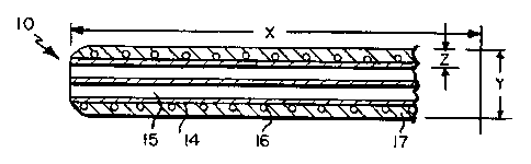
Refernng now to FIGS. 1 and 2, a catheter device 10 of the present invention
is shown to include a shaft 11 having a proximal end 12 and a distal end 13; a
lubricious liner 14 defining a plurality of lumens 15. (In accordance with
conventional practice regarding medical devices, "proximal end" designates
that end
which is closest to the medical personnel manipulating the device, and "distal
end"
designates the opposite end that is placed within a patient.) The lubricious
liner 14 is
surrounded by reinforcing member 16, and an outer jacket 17.
The components of the catheter of present invention may be made from a
number of materials as will be appreciated by those skilled in the art.
In certain preferred embodiments, catheter 10 has dimensions of about 12 to
48 in length (distance x in FIG. 2) and about 0.053 inches (4 French) to 0.263
(20
French) in diameter (distance y in FIG. 2). Other dimensions, including longer
sheaths, also will be suitable.
Preferably, the composite walls of the catheter range from about 0.004 inches
to about 0.12 inches, more preferably, from about 0.004 inches to about 0.008
inches
in thickness (distance z in FIG. 2).
Catheter shaft 11 is constructed by applying, e.g., slipping, lubricious
liners 14
over a profiled supporting mandrel (not shown). The desired number of lumens
determines the mandrel profile so that the composite construction represents
the
desired overall shape of the catheter shaft profile.
Typically, this profile shape is round but it can be oval or some other
geometric derivative. For example, if a round catheter shaft profile is
desired in a
_6_
CA 02378720 2002-O1-09
WO 01/07101 PCT/US00/19804
two-lumen configuration, then one of the two mandrels will typically have a
crescent
shape and one will be round. The round mandrel will be sized to fit into the
crescent
shape so that the composite profile will be approximately round.
In preferred embodiments of the present invention, the lubricious liner 14
comprises a fluoropolymer material. Particularly preferred fluoropolymers
include
polytetrafluoroethylene and fluorinated ethylene-propylene polymers. Most
preferably, the lubricious liner comprises polytetrafluoroethylene.
In another preferred aspect of the present invention, the outer surface of the
lubricious liner 14 is etched or otherwise modified to improve the adhesion
characteristics of the material.
Once the lubricious liners 14 have been placed over the supporting mandrels,
the mandrels are manually bundled and fed into a braider that will apply a
reinforcing
member 16 over the lubricious liners 14. The reinforcing member 16 reduces the
possibility of kinking or bending of the catheter during and after entry into
the
vasculature of the patient.
A physical wrapping of the bundles of liners and mandrels also can be
utilized.
More specifically, a heat shrink coating can be applied over bundles of liners
and
mandrels prior to feeding same into the assembly into a braider. Suitable
materials
for forming such a thin-walled heat shrink include e.g. PET or a fluoropolymer
such
as polytetrafluoroethylene or fluorinatedethylenepropylene.
Preferably, the braider unit includes a facilitating mechanism for entry of
the
bundle of liners, e.g. a pair of rollers to uniformly fed the bundles into the
braider
apparatus.
In preferred embodiments, the reinforcing member 16 comprises round or
profiled materials, such as flat or rounded stainless steel wire. MP-35, a
stainless
alloy, is another suitable material for construction of the reinforcement
member.
These materials may be braided in different patterns or densities to provide a
custom
degree of kink resistance, torque or both.
CA 02378720 2002-O1-09
WO 01/07101 PCT/US00/19804
In alternate preferred embodiments of the present invention, the reinforcing
member 16 comprises Nitinol, Kevlar or a polymeric monofilament type of
material,
such as a nylon, or other polymeric material.
In yet another aspect of the present invention, the reinforcing member 16 may
be terminated proximal to the distal end of the catheter shaft, and a spiral
reinforcing
member (a helical coil of flat or round material) can be manually slid into
its place.
This embodiment of the present invention is particularly useful when kink
resistance
and improved flexibility is needed at the distal tip 13 of the catheter 10.
The pitch of the braiding or coil may be varied in order to produce a
reinforcing member with non-uniform spacing between the braiding or coil
turns.
Such pitching provides yet another way to vary the flexibility and
torquability of the
catheter 10 in order to tailor the device to a particular use, procedure or
access site,
etc. For example, suitably the spacing between braiding or coil turns of the
reinforcements will vary from about 0.010 to 0.050 inches over the length of
the
1 S reinforcement. The pitch also will preferably vary over defined regions of
the
reinforcement member. Hence, for example, for a four inch reinforcement, the
first
inch of the member proximal end may suitably have a 0.010 spacing between
coils,
the next two inches may have a spacing of 0.020 inches between coils and the
final
inch may have a spacing of 0.025 inches between coils.
Once the braid or combination of reinforcing members has been applied to the
composite, mandrel supported liners, an extruded outer jacket 17 is applied to
the
entire length of the reinforced shaft 11 by sliding it in place over the
reinforcing
member 16.
In preferred embodiments of the present invention, outer jacket 17 surrounds
the outer surface of the catheter. The outer jacket comprises a polymeric
material, e.g.
a polyurethane, polyethylene, polyester, nylon, nylon copolymer such as a
polyetherblockamide (PEBA), and the like. Such materials of construction can
be
used in a variety of durometers as desired.
Referring now to FIG. 3, in particularly preferred embodiments of the present
invention, the outer jacket 17 comprises numerous segments 18, each with
differing
_g_
CA 02378720 2002-O1-09
WO 01/07101 PCT/US00/19804
durometers so that the shaft stiffness can be varied from one end of the
catheter to the
other. The segments 18 may be comprised of the same or different material.
The number of differing segments 18 which form outer jacket 17 can range
from two to as many as required, but typically includes up to ten. These
segments 18
are slid into place over the length of the catheter shaft 11 and are of
appropriate length
and in the appropriate order to create the desired degree of transition from
stiff to
flexible. This particular feature enables one to readily alter the flexibility
of the
catheter. In that way, the present invention provides a catheter which is easy
to
handle and maneuver, and that is non-traumatic to the vasculature of the
patient.
In particularly preferred embodiments of the present invention, the distal end
13 of the catheter 10 is more flexible relative to the shaft portion of the
catheter. This
construction further provides for non-traumatic entry of the device into the
vasculature of the patient.
In yet another embodiment of the present invention, the outer jacket 17
further
comprises a radiopaque filler 19. Typically, the radiopaque filler 19 is
blended into
the polymeric material of the jacket prior to extrusion. Preferably, this
filler ranges in
percentages from about 5% to about 40% by weight and comprises barium sulfate,
tungsten, bismuth sub-carbonate or bismuth trioxide. Such a configuration
permits
visualization of the catheter within a patient by x-ray or fluoroscopic
procedures.
Catheter 10 also may comprises a radiopaque tracer ring (not shown),
preferably positioned at or proximate to the distal tip of the sheath. Use of
such a
radiopaque marker permits visualization of the sheath distal end within a
patient by
x-ray or fluoroscopic procedures.
FIG. 4A shows a preferred catheter 30 of the invention having a segmented
portions of different hardness. The catheter 30 includes tapered distal tip 32
and
exterior reinforcement member 34 that preferably terminates before tip 32 as
depicted
in FIG. 4A. As discussed above, the reinforcement member suitably may have a
variety of configurations, such as a generally flat wire spiral as shown in
FIG. 4A, or
a round wire braid as shown in FIG. 6B. Also, other wrapping configurations
will be
-9-
CA 02378720 2002-O1-09
WO 01/07101 PCT/US00/19804
suitable with those materials, e.g., a round wire can be configured as a
spiral
reinforcement, and the flat wire can be configured as a braided reinforcement.
Catheter 30 also has segments of varying hardness, specifically distal segment
30A is comparatively the least hard portion of the sheath; a middle sheath
segment
30B that has an intermediate hardness and greater hardness than distal segment
30A;
and a proximal segment 30C that is the most hard the three depicted segments.
The
catheter also has lubricous inner liners 36 such as PTFE or other
fluoropolymer for
the entire catheter length.
FIG. 5 shows a further preferred catheter 40 of the invention that has tapered
distal end 41 and includes multiple lumens 42 and 44 that include lubricous
liners 42a
and 44a respectively, preferably a fluorinated materials as discussed above.
Catheter
40 includes reinforcement member 46 that includes a coiled portion 46a and
braided
section 46b. Each of coiled portion 46a and braided section 46b may be flat
wire or
round wire, or other configured wrapped reinforcing material.
Catheter 40 also preferably includes segments along the catheter that differ
in
hardness. More particularly, distal catheter segment 40A is typically
constructed to
be the softest portion of the several longitudinal catheter segments; segment
40B is
suitably harder and/or constructed of different materials) than distal segment
40A;
segment 40C is suitably harder and/or constructed of different materials) than
distal
segment 40B; and proximal segment 40D is suitably harder and/or constructed of
different materials) than distal segment 40C.
As discussed above, the invention also provides methods of manufacturing an
improved catheter with a kink-resistant, reinforced catheter shaft having a
plurality of
interior lumens which are surrounded by a lubricious liner.
In preferred aspects, such methods generally include the steps of applying,
e.g., slipping, the lubricious liners over a profiled supporting mandrel to
construct the
catheter shaft, applying a reinforcing member over the lubricious liners,
applying an
outer jacket to the length of the reinforced catheter shaft, and molding the
jacket to the
reinforced catheter shaft.
- 10-
CA 02378720 2002-O1-09
WO 01/07101 PCT/US00/19804
In preferred embodiments of the present invention, such methods further
comprise altering segments of the outer jacket with materials) having
differing
durometers or materials so that the shaft stiffness can be varied from one end
of the
catheter shaft to the other.
S Once the outer jacket or jacket segments are in place, a covering of heat
shrinkable tubing is applied over the entire assembly. Preferably, the heat
shrinkable
tubing comprises at least one of a fluorinated ethylene propylene or
polytetrafluoroethylene polymer.
The heat shrinkable tubing is recovered by applying heat from an external
source, procedures for which are well known to those skilled in the art. This
assembly is passed through a heated die of a controlled size and at a
controlled rate to
heat fuse the outer jacket segments with each other. The outer jacket is also
melted
through the reinforcing member and bonded to the etched outer surface of the
lubricious liner.
The final stage involves removing the heat shrinkable tubing from the outside
of the assembly and removing the supporting mandrels from the inside of each
lumen.
Another application would be in the construction of a catheter with a
steerable
distal tip. These devices typically use wires attached to the catheter handle
and distal
tip to move the tip at an angle from the centerline. When these wires are
articulated
back and forth, the tip of the catheter is deflected and directed to an
appropriate
anatomical location. Additionally, the multi-lumen construction of catheter of
the
invention provides for use of one, two or more smaller lumens as passageways
for
wires to articulate the distal tip.
The novel design of the present invention provides an improved catheter
device that incorporates a mufti-lumen, reinforced catheter shaft
construction. A
reinforcing member is also included for kink-resistance. A variably flexible
outer
jacket minimizes trauma to the vascular system of the patient, and offers the
attendant
medical personnel a high degree of torsional control with respect to the
catheter.
The terms and expressions which have been employed herein are used as
terms of description and not of limitation. There is no intent, in the use of
such terms
-11-
CA 02378720 2002-O1-09
WO 01/07101 PCT/US00/19804
and expressions, of excluding any of the equivalents of the features shown and
described or portions thereof, but it is recognized that various modifications
are
possible within the scope of the invention claimed.
-12-