Note: Descriptions are shown in the official language in which they were submitted.
CA 02378975 2002-02-05
-1-
DESCRIPTION
ADHESIVE TAPE APPLICATOR
TECHNICAL FIELD
The present invention relates to an adhesive
tape applicator for applying an adhesive tape to door sash
frames of automobiles.
BACKGROUND ART
Conventionally, pillars and door sash frames of
automobiles have been painted in black or other colors in
order to improve their appearance. However, painting
requires additional manufacturing steps such as masking.
Painting has also been causing environmental problems of
evaporation of solvent into the atmosphere.
In recent years, in order to solve such problems,
adhesive tapes made of vinyl chloride and coated with an
adhesive have been generally applied to door sash frames
and the like. As shown in Fig. 14, an adhesive tape T
comprises a base material TB having an adhesive layer TS
on one side and a release liner TL covering the adhesive
layer TS. The base material TB may be provided thereon
' ' CA 02378975 2002-02-05
-2-
with a transparent protective layer TP, if necessary. The
base material TB is colored black or other colors.
However, the recent automobile designs include
greatly curved door sash frames. Moreover, in some cases,
some portions of the door sash frames are narrowed because
of the process of curving the frames. When an adhesive
tape is applied to the door sash frames of automobiles
using an adhesive tape applicator, conventional adhesive
tape applicators can not be moved smoothly along the
curves, narrowed portions and the like. Thus, the
adhesive tape may be deviated from the door sash frames.
In addition, although the application of
adhesive tapes to door sash frames of automobiles is
carried out in assembly line, conventional adhesive tape
applicators require considerable time for positioning and
setting the applicator on the door sash frames.
Further, conventional adhesive tape applicators
have the structure to give tension to an adhesive tape,
whereby the adhesive tape is elongated. Therefore,
although the length of the adhesive tape is preliminarily
determined according to the size of an object face, the
tension of application makes the adhesive tape becomes too
long for the object face after being applied.
Since the application of adhesive tapes to door
sash frames of automobiles is carried out in assembly line,
CA 02378975 2002-02-05
~ T
-3-
an adhesive tape applicator which is capable of improving
the appearance, manufacturing efficiency and quality of
the door sash frames is desired.
Thus, an object of the present invention is to
provide an adhesive tape applicator which is capable of
applying an adhesive tape stably and accurately and to
provide an adhesive tape applicator which can realize
improved operability and apply the adhesive tape at a high
speed.
DISCLOSURE OF INVENTION
The above object of the present invention can be
achieved by an adhesive tape applicator which applies a
main body of the adhesive tape to a door sash frame of an
automobile while removing a release liner from the
adhesive tape as the adhesive tape applicator is moved
along the door sash frame, the adhesive tape applicator
comprising a pressing portion having a pressing area for
pressing the adhesive tape against the door sash frame and
a means for altering the direction of advance of the
adhesive tape which changes a feeding path of the adhesive
tape and leads the adhesive tape to the pressing area, the
means for altering the direction of advance of the
adhesive tape comprising a contact portion which is in
contact with the main body of the adhesive tape and leads
CA 02378975 2002-02-05
-4-
the main body of the adhesive tape towards a pressing area
of the pressing portion while feeding the release liner in
a straight line path to remove the release liner, and an
adhesive tape guide means which is disposed upstream of
the contact portion relative to the direction of advance
of the adhesive tape and contacts with the release liner
to direct the adhesive tape towards the contact portion,
an upstream portion of the adhesive tape guide means
allowing the adhesive tape to advance substantially
without resistance.
The above object of the present invention can be
also achieved by an adhesive tape applicator to apply an
adhesive tape with a release liner to the door sash frame
of an automobile while removing the release liner as the
adhesive tape applicator is moved along the door sash
frame, the applicator comprising a holding means which
slidably holds the door sash frame, the holding means
comprising a guide means which slidably holds the door
sash frame and guides the applicator along the door sash
frame, a pressing portion which presses the adhesive tape
and an adhesive tape guide means which separates the
release liner from the adhesive tape and leads the
adhesive tape to the pressing portion, the adhesive tape
guide means comprising (i) a tape passage which is
disposed at the front side of the pressing portion in the
CA 02378975 2002-02-05
-5-
sliding direction of the applicator and extends from the
vicinity of the pressing point of the pressing portion to
a rear position in the pressing direction and (ii) a
movable part which is slidably supported in the same or
opposite direction of the applicator and intersects the
tape passage transversely.
The pressing portion may be an elastic roller
whose rotation shaft may be disposed across the guiding
direction of the guide means.
The guide means may have a guide groove engaging
with the door sash frame, the holding means may have a
pressing lever which is resiliently urged towards the
guide groove, the pressing lever may have a pressing
member which can be moved towards or away from the guide
groove by operating the pressing lever.
The guide groove comprises at least two bottom
guide rollers disposed in the guiding direction at its
bottom. The pressing member of the pressing lever may be
a pressing roller. The guide groove is preferably
equipped with side guide rollers at its side walls.
The adhesive tape applicator has a guide channel
for release liner extending in the sliding direction of
the applicator from the tape passage.
CA 02378975 2004-12-14
Sa
According to another aspect of the present invention,
there is provided an adhesive tape applicator to apply an
adhesive tape with a release liner to the door sash frame
of an automobile while removing the release liner as the
adhesive tape applicator is moved along the door sash
frame, the applicator comprising a guide roller and a
pressing roller mounted opposite to the suide roller, the
passing roller and the suide roller cooperating for
slidably hold the door sash frame and guide the applicator
along the door sash frame, an elastic roller which presses
the adhesive tape, and an adhesive tape guide comprising
(i) a tape passage which is disposed at the front side of
the elastic roller in the sliding direction of the
applicator and extends from the vicinity of a pressing
point of the elastic roller to a rear position in the
pressing direction, and (ii) a movable part which is
slidably supported in the same or opposite direction of the
applicator and intersects the tape passage transversely.
CA 02378975 2002-02-05
-6-
BRIEF DESCRIPTION OF DRAWINGS
Fig. 1 is a perspective view which shows an
embodiment of the adhesive tape applicator according to
the present invention.
Fig. 2 is a front view of the adhesive tape
applicator shown in Fig. 1.
Fig. 3 is a rear view of the adhesive tape
applicator shown in Fig. 1.
Fig. 4 is a front view which shows the adhesive
tape applicator shown in Fig. 1 when the pressing lever is
open, corresponding to Fig. 2.
Fig. 5 is a plan view of the adhesive tape
applicator shown in Fig. 4.
Fig. 6 is a right side view of the adhesive tape
applicator shown in Fig. 4.
Fig. 7 is a bottom view of the adhesive tape
applicator shown in Fig. 1. Fig. 7(a) shows the
applicator when the movable part is inserted, and Fig. 7
(b) shows the applicator when the movable part is pulled
out.
Fig. 8 is a sectional view taken along line B-B
of Fig. 5.
Fig. 9 is a sectional view taken along line A-A
of Fig. 2, when the movable part is at its outermost
CA 02378975 2002-02-05
_7_
position.
Fig. 10 is a sectional view corresponding to Fig.
9, when the movable part is at its innermost position.
Fig. 11 is a perspective view which shows the
adhesive tape applicator of Fig. 1 when in use.
Fig. 12 is a sectional view which shows a use of
the adhesive tape applicator of Fig. 1.
Fig. 13 is a perspective view which shows an
adhesive tape for use in the adhesive tape applicator
according, to the present invention.
Fig. 14 is a sectional view taken along line C-C
of Fig. 13.
Fig. 15 is a sectional view which corresponds to
Fig. 12 and shows an embodiment of the adhesive tape
applicator of Fig. 1 in which some modification is made.
Fig. 16 is a perspective view which shows
another preferable embodiment of the adhesive tape
applicator according to the present invention in the same
view as in Fig. 1.
Fig. 17 is a perspective view of the adhesive
tape applicator of Fig. 16 in the same view as in Fig. 11.
Fig. 18 is a perspective view of the adhesive
tape applicator of Fig. 16 in the same view as in Fig. 12.
CA 02378975 2002-02-05
_8_
BEST MODE FOR CARRYING OUT THE INVENTION
Preferred embodiments of the adhesive tape
applicator according to the present invention will be
explained referring to Figs. 1 to 13 below.
Fig. 8 shows a section of a door sash frame F to
which the adhesive tape is applied by the present
applicator. As shown in this Fig. 8, such a door sash
frame F integrally comprises a main frame body F1 having a
surface to which an adhesive tape T is applied, a
reinforcing projection F2 projecting from the rear side of
the main frame body F1 and a weather strip-attached
portion F3 provided on the outer surface of the
reinforcing projection F2. In the description below, an
embodiment of an adhesive tape applicator having such a
structure which is suitable for applying adhesive tape to
an inner surface of the door sash frame F will be
explained.
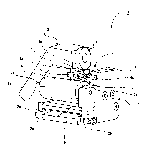
An adhesive tape applicator 1 is provided with a
base 2 and a pressing lever 3 mounted on the base 2. A
guide groove 4 is formed on the base 2. Bottom guide
rollers 5"'5 are disposed in a guiding direction at the
bottom of the guide groove 4.
On the base 2 is mounted a pressing portion 6
comprising an elastic roller 6a for pressing an adhesive
r-
CA 02378975 2002-02-05
-9-
tape T. The rotation shaft of the elastic roller 6a is
disposed across the guiding direction of the guide groove
4.
A pressing lever 3 is pivotally mounted on the
base 2. The pressing lever 3 has at one end a pressing
roller 7 which forms the pressing member. The pressing
roller 7 is resiliently urged towards the bottom guide
rollers 5~-~5 by a torsion spring 8 (see Fig. 8).
Thus, the holding means for slidably holding the
door sash frame F can be formed by the elastic roller 6a,
bottom guide rollers 5~~~5 and pressing roller 7. The
elastic roller 6a can be formed by covering its rotation
shaft with an elastic material such as soft rubber, sponge,
etc.
When applying the adhesive tape T to the door
sash frame F with the elastic roller 6a, the shape of the
elastic roller 6a changes depending on the outer shape of
the door sash frame F with the force applied to the soft
elastic roller 6a in the direction of applying the
adhesive tape T. Accordingly, the adhesive tape T can be
fittingly applied to the door sash frame F and no air
bubble is caught therebetween. However, forcing the
elastic roller 6a to the outer surface of the door sash
frame F increases the contact portion therebetween. The
increased contact portion and the pressure applied thereto
CA 02378975 2002-02-05
-10-
may cause largish friction between the adhesive tape T and
elastic roller 9a. Although the friction is not
problematic when applying tape to straight portions of the
door sash frame F, it causes many problems at curved
portions: when the elastic roller 9a turns to the
direction of the curve, the elastic roller 9a may twist
the adhesive tape T and thus the position of the adhesive
tape T is not stable; twists in the adhesive tape T may
result in wrinkles when the curve is sharp. In this case,
a foamed material produced by cutting a foamed substance
such as a sponge rubber is used to form at least the outer
layer of the elastic roller 9a. The surface of such a
foamed material exhibits a coefficient of friction much
lower than a non-foamed material, even though it is made
of a material having a relatively high coefficient of
friction such as natural rubber, synthetic rubber,
silicone rubber and the like. Accordingly, the use of a
foamed substance for the elastic roller achieves stable
and desirable positioning of the adhesive tape T at curved
portions, as well as straight portions, of the door sash
frame F. The use of a foamed substance also prevents
wrinkle in the adhesive tape T.
Side guide rollers 4a~~~4a may be provided on the
side walls of the guide groove 4. The side guide rollers
4a~~~4a constructs a guide means which slidably holds the
CA 02378975 2002-02-05
-11-
door sash frame F therebetween and guides the applicator
along the door sash frame.
The elastic roller 6a is supported by bearing
portions 2a, 2a projecting from both sides of the base 2.
A gap H is formed between the elastic roller 6a and base 2
so that the adhesive tape T can pass through (see Fig. 9).
The gap H is disposed at the front side of the pressing
portion in the sliding direction of the applicator (the
direction that the applicator is moved: the direction
shown by arrow X in Fig.lO and extends from the vicinity
of the pressing point of the pressing portion to a rear
position in the pressing direction (the direction shown by
arrow P in Fig. 9) and a movable part which is slidably
supported in the sliding direction of the applicator or
the opposite direction across the tape passage. This gap H
forms a tape passage K (Fig. 9, Fig. 7(b)).
Slide grooves 2b, 2b are formed on the inner
side walls of the base 2 across the inner walls of bearing
portions 2a, 2a (see Fig. 1). A slidable plate 9 which
forms the movable part is inserted into the slide grooves
2b, 2b. A hole 9a to insert a finger is formed on the
slidable plate 9 (Fig. 7).
The slidable plate 9 has a first stopping means
and second stopping means which restrict the slidable
range. The first stopping means can be provided, for
CA 02378975 2002-02-05
-12-
example, by embedding a ball plunger (not shown) into a
side wall of the slidable plate 9 and forming the
concavity engaging the ball of the ball plunger inside the
slide grooves 2b, 2b so that the slidable plate 9 is
stopped at the position shown in Figs. 7(a) and 10. The
second stopping means can be also formed by providing a
stepped portion 9b with the slidable plate 9 and fixedly
mounting a stopper 2c (Figs. 3 and 7) which stops the
stepped portion 9b to the slide grooves 2b so that the
slidable plate 9 is stopped at the position shown in Figs.
7 (b) and 9.
A baffle plate 2d is connected between the
bearing portions 2a and 2a of the base 2. The baffle
plate 2d is given a width which does not close the tape
passage K and provided to rearward of the slide grooves 2b,
2b in the pressing direction (the direction shown by arrow
P in Fig. 9).
A first pin 2e is fixed on the bearing portions
2a and 2a to extend between the slide grooves 2b and 2b.
The first pin 2e and the slidable plate 9 form a gap
slightly wider than the thickness of the adhesive tape T
when the slidable plate 9 is at an engaged position as
shown in Fig. 10. A second pin 2f is connected between
the bearing portions 2a and 2a in the vicinity of the
elastic roller 6a, slide grooves 2b and tape passage K.
CA 02378975 2002-02-05
-13-
In the base 2 is formed a gap G extending from
the vicinity of the second pin 2f along the slidable plate
9 in the sliding direction of the applicator (in the
direction shown by arrow X in Fig. 10) (Figs. 8 and 9).
Next, how to use the adhesive tape applicator 1
having the above structure will be explained. The
adhesive tape T used herein is similar to those which are
conventionally known except that as shown in Fig. 13, the
adhesive tape T has a release liner TL which is provided
with a cut line C at a predetermined distance from the
front end of the tape. Hereinafter the term "base
material" denotes an adhesive layer TS and protective
layer TP collectively.
First, as shown in Fig. 9, the slidable plate 9
is pulled outwardly from the base 2. Then, the adhesive
tape T is inserted through a tape passage K with the
protective layer TP facing the elastic roller 6a as shown
by the chain line in Fig. 9. When doing so, the cut line
C of the release liner TL is positioned as close as
possible to the slide grooves 2b.
Next, as shown in Fig. 10, the slidable plate 9
is pushed along the slide grooves 2b until the slidable
plate 9 is stopped at a predetermined position (the
position shown in Fig. 10) by the above first stopping
2~ means (not shown).
CA 02378975 2002-02-05
-14-
In this state, the pressing lever 3 is moved
against the resilient force of the torsion spring 8 to
detach the pressing roller 7 from the guide groove 4. The
front end of the adhesive tape T is applied at a
predetermined position of the inner side of the door sash
frame F (see Fig. 11). The reinforcing projection F2 of
the door sash frame F is inserted between the side guide
rollers 4aw4a of the guide groove 4 (see Fig. 8). The
pressing lever 3 is returned to its first position by the
resilient force of torsion spring 8 to hold the
reinforcing projection F2 of the door sash frame F between
the pressing roller 7 and the bottom guide rollers 5"'5
(Figs. 8 and 11).
In this manner, the adhesive tape applicator 1
is attached to the door sash frame F and slid in the
sliding direction of the applicator (the direction shown
by arrow X) along the door sash frame F as shown in Figs.
11 and 12.
As the adhesive tape applicator 1 is slid, the
adhesive tape T is fed into the adhesive tape applicator 1
and bent through 90° by the second pin 2f. However, the
release liner TL made of paper, plastic film or the like
is not bent by the second pin 2f. Thus, the release liner
TL separates from base material TB (comprising the
protective layer TP and adhesive Layer TS collectively) at
CA 02378975 2002-02-05
-15-
the cut line C and advances straightly through the gap G
which forms the guide channel for release liner to the
outside of the adhesive tape applicator 1. Thus, an
adhesive tape guide means to separate the adhesive tape T
from the release liner TL and lead the base material to
the elastic roller 6a can be formed. A release liner TL',
extending from the front end of the tape to the cut line C,
can be removed after the adhesive tape T, extending from
the cut line C to the rear end of the tape, is applied to
the door sash frame F.
When excessive tension is applied to the
adhesive tape, the adhesive tape T may be elongated during
application. Therefore, it is preferable to minimize the
friction between the slidable plate 9 and adhesive tape T
by, for example, forming the area of the slidable plate 9
which contacts the adhesive tape T with a material having
a low coefficient of friction or as shown in the sectional
view of Fig. 15, providing a rotatable roller 9a at the
end portion of the slidable plate 9 corresponding to the
above contact portion.
Next, the ad~ntage according to of the adhesive
tape applicator 1 having the above structure will be
explained.
The adhesive tape applicator 1 holds the
reinforcing projection FG of the door sash frame F between
CA 02378975 2002-02-05
-16-
the bottom guide rollers 5~~-5 and pressing roller 7 and
guides the outer surface of the main frame body F1 and the
reinforcing projection F2 of the door sash frame F with
the side guide rollers 4a~~~4a. Accordingly, the adhesive
tape applicator 1 can be positioned in two directions
perpendicular to the longitudinal direction of the door
sash frame F (directions Y and Z and their opposite
directions in Fig. 11) and the position of the adhesive
tape applicator 1 is stabilized, preventing mispositioning
of the adhesive tape T.
The adhesive tape applicator 1 can be moved on
rollers (4a~~~4a, 5"'5, 6a, 7) along the door sash frame F
so that the applicator can travel at a high speed.
The pressing lever 3 is resiliently urged by the
torsion spring 8. Thus, when the pressing lever 3 holds
the door sash frame F, it can apply the desired pressure
to the elastic roller 6a forming the pressing portion.
The use of the elastic roller 6a also enables the
application of an substantially uniform pressure to the
entire surface of the door sash frame F even if the
surface is curved in the widthwise direction. This
prevents unevenness in the applied adhesive tape T. The
use of one pressing roller 7 of the pressing lever 3
enables the applicator to stably stay on door sash frame
even if the curved portion of the door sash frame F is
CA 02378975 2002-02-05
-17-
narrow, preventing mispositioning of the adhesive tape T.
Moreover, the leverage action of the pressing lever 3
facilitates the holding operation of the door sash frame F
by the adhesive tape applicator 1 with one hand.
The adhesive tape applicator 1 is capable of
continuously separating the release liner TL from the
adhesive tape T and applying the adhesive tape T to the
door sash frame F without failure by the above adhesive
tape guide means. The applicator is also advantageous in
operability because it can carry out such separation by
the simple operation of inserting the adhesive tape T into
the tape passage K and moving the slidable plate 9.
Further, the gap G which forms the guide channel for
release liner achieves more effective separation of the
release liner TL.
Next, other preferred embodiments of the
adhesive tape applicator according to the present
invention will be explained referring to Figs. 16 to 18.
In the embodiments described below, the same components as
in the above embodiments are used. Among them, however,
the baffle plate 2d and first pin 2e are not used in the
embodiments described below. Thus, the components are
denoted by the same numerals and their detailed
description is eliminated.
The second pin 2f shown in Fig. 18 contacts the
, , CA 02378975 2002-02-05
-18-
side of the main body (TB, TS and TP) of the adhesive tape
T. The second pin 2f also forms the contact portion which
separates the release liner TL from the fed adhesive tape
while feeding the release liner in a straight line path
and leads the main body of the adhesive tape towards a
pressing area of the pressing portion. The adhesive tape
guide means 9' is disposed upstream of the contact portion
relative to the direction of advance of the adhesive tape
and contacts the release liner TL to direct the adhesive
tape T towards the contact portion. These contact portion
(second pin 2f) and adhesive tape guide means 9' form a
means for altering the direction of advance of tape which
leads the feeding path of the adhesive tape T to the
pressing area.
The contact portion can be also formed by the
portion of the elastic roller 6a opposite to the pressing
area without using the second pin 2f. However, forming
the contact portion by using the second pin 2f affords
accurate control of the position where the release liner
TL is removed.
As shown in Fig. 18, according to the adhesive
tape applicator 1' having such a structure, the adhesive
tape T can advance in an upstream portion of the adhesive
tape guide means 9' substantially without resistance.
Therefore, the main body of the adhesive tape is not being
CA 02378975 2002-02-05
-19-
elongated by a tension applied to the main body of the
adhesive tape after the release liner is removed therefrom.
As is apparent from the above description, the
adhesive tape applicator according to the present
invention is capable of stabilizing its position during
application of the adhesive tape, accurately applying the
adhesive tape at a high speed, stably supplying the
adhesive tape, etc.