Note: Descriptions are shown in the official language in which they were submitted.
CA 02379310 2002-O1-10
WO 01/03803 _ 1 _ PCT/US00/18964
IMPROVED MIST ELIMINATOR
Background of the Invention
The present invention relates to an apparatus for the separation of gas
and liquid from a flowing mixture of gas and liquid. In particular, the
invention
relates to an improved gas/liquid separator of the cyclonic variety.
In various industrial processes, such as in washing wood pulp, it is
advantageous to draw air from over a resen~~oir of liquid by means of a vacuum
provided by a blower intake. The air is usually drawn through the blower and
provided under pressure to a portion of an apparatus, such as a pulp washer,
to create
a region of positive pressure. However. the air drawn by the vacuum created by
the
blower may have liquid or solid particles entrained therein, particularly
where the
liquid has foam or froth covering its surface. For proper operation of the
blower and
the apparatus, it is necessary to separate the entrained particles from the
air before the
air is taken in by the blower.
Various means of separating a gas from a gas/liquid flow mixture are
I S known in the art. In particular, separation of liquid and solid particles
from gas
streams by cyclonic action is known. For example, a contact-and-separating
element
of a vortex tray of a liquid-gas mass-transfer apparatus using cyclonic
separation is
disclosed in U.S. Pat. No. 4,838,906 to Kiselev. Similarly, a dust collection
system
using cyclonic separation is disclosed in LT.S. Pat. No. 2,393,112 to Lincoln.
In a typical cyclonic separator, a gas mixture having particles
entrained therein is drawn vertically upward. A cyclonic rotation is imparted
to the
flowing mixture, typically by means of helical or spiral vanes. Centrifugal
force
causes heavier particles to be forced radially outwardly toward the outer
periphery of
the flow mixture where the particles drop back downward under the force of
gravity.
The gas mixture without the heavier particles continues upwardly.
Cyclonic gas/liquid separators may be used in a flat bed wood pulp
washer generally similar in construction and mode of operation to a
Fourdrinier
paper machine incorporating an endless foraminous belt ("wire"), a headbox
which
delivers the pulp suspension in a pulping liquor to one end of a horizontally
traveling
CA 02379310 2002-O1-10
WO 01/03803 _2_ PCT/US00/18964
upper run of the wire, successive washing zones along the length of the run,
and
means at the downstream end of the run for receiving and removing the
resulting
washed pulp. Pulp washers of this type, manufactured by the assignee of the
present
invention in accordance with Ericsson U.S. Pat. No. 4,154,644 of 1979, have
been
notably successful, and the present invention was developed to improve the
operation
and results obtained by such pulp washers.
The operation of a pulp washer of this type may be described as being
according to the displacement washing principle. That is, once the pulp mat
has been
formed, it is not rediluted, but simply is subjected to repeated washings by
application on top of the mat of washing liquid with the liquid applied in
each
washing zone having a lower concentration of liquor than the filtrate from the
preceding zone. The liquid applied in each zone enters the mat substantially
en
masse and thereby displaces the liquid which was carried into the zone in the
mat and
causes it to drain therefrom through the wire.
The mechanical elements of a washer according to the Ericsson patent
include a hood which encloses the entire apparatus downstream from the
headbox,
and a series of receptacles below the operating run of the wire in sealed
relation with
the hood. In operation, vacuum is applied to the receptacles, and/or gas
pressure is
developed within the hood, to augment the action of gravity in forcing the
washing
liquid through the pulp mat on the wire. Gases and vapors drawn through the
wire
into the upper spaces in the receptacles are recycled back to the hood to
increase the
pressure differential above and below the wire.
In the pulp washer, a gas/liquid separator or mist eliminator is
attached to each of the receptacles at a gas outlet on top of the receptacle
to thereby
2~ permit the gases and vapors to be drawn from the flat top receptacles
through the
mist eliminator to the suction side of a pump or fan that recycles the gas, in
this case
air, to the hood. However, entrained within the gases and vapors drawn from
the
receptacle are particles of mist and foam from the space between the wire and
the
pulping liquor.
Prior art mist eliminators employing cyclonic separating means have
been used to remove particles of mist and foam from the gas flow before the
gas
CA 02379310 2002-O1-10
WO 01/03803 ., PCT/US00/18964
_J_
reaches the pump or blower. The typical mist eliminator has a cylindrical
housing
arranged vertically proximate the top of the receptacle with a vacuum line
attached to
the top end. The gas inlet is positioned above the level of the liquor with
cyclonic-
flow-inducing means, typically helical vanes or a swirler, positioned within
the inlet.
Droplets of mist and particles of foam are hurled radially outwardly by
centrifugal
force from the gas/liquid flow to drop back down into the liquor under the
force of
gravity.
However, in many cases the upward draft of gas through the mist
eliminator impinges upon the falling, separated liquid droplets. This tends to
retard
the separation of undesired droplets of mist and particles of foam entrained
within
the gas flow. Thus, incomplete separation of foreign matter from the gas
results.
Mist and foam entrained within the gas flow result in a lower pressure
differential
being developed between the hood and the receptacle, thereby reducing the
efficiency
of the pulp washer.
In accordance with the disclosure of WO Publication 98/29179 (of
common assignment herewith) an improved mist eliminator is provided wherein an
annular zone is formed in the separator where falling droplets of separated
water and
liquid drain downwardly in the device substantially without resistance from
countercurrent flow of gas and liquid.
Although the mist eliminator set forth in the aforementioned WO
Publication has proven commercially successful, it was found that in some
instances,
where dense foams were encountered in the suction box, turbulence was actually
increased in the liquid directly beneath the separator, leading to inefficient
separation. Accordingly, there is a need in the art for a mist eliminator
device of
enhanced efficiency that is capable of separating foam components that may
exist in
the suction box.
Summary of the Invention
These and other objects of the invention are met by the provision of a
cyclonic separation device wherein two distinct cyclonic action zones are
provided to
perform the desired separation of the liquid components from the gas
component.
CA 02379310 2002-O1-10
WO 01/03803 -4- PCT/US00/18964
The device includes a generally elongated cylindrical housing with inlet end
and
outlet end disposed at opposite axial ends of the cylinder. Within the
cylinder and at
an approximate medial position along the longitudinal axis of the housing, a
swirl
imparting vane structure is located. This vane structure forms a boundary
defining a
upstream cyclonic zone and downstream cyclonic action zone. The location of
the
swirl imparting vane structure at an approximate mid-point along the length of
the
cylinder contrasts with many prior art designs where the swirl vanes are
located
adjacent the inlet end of the separator.
The outlet of the housing is connected to a suitable suction source
which draws the gas/liquid mixture to be separated into the inlet portion of
the
housing, passing Generally upwardly through the housing in an upstream to
downstream direction. The mixture is first separated in the upstream cyclonic
zone
with an additional separation performed in the downstream cyclonic action
zone.
Other objects and advantages of the invention will be apparent from
the following description, the accompanying drawings and the appended claims.
Brief Description of the Drawings
Figure 1 is a view in side elevation showing a horizontal Ericsson-
type of washer that may incorporate, as a component thereof, an improved mist
eliminator in accordance with the invention
Figure 2 is a cross-sectional view taken along the lines and arrows 2-2
of figure 1 and detailing the system location of the improved mist eliminator
of the
invention;
Figure 3 is a partially broken away side elevational view of a
2~ improved mist eliminator in accordance with the invention shown in its
position in a
suction box receptacle of the type provided in Ericsson washers
Figure 4 is a partially broken away side elevational view of the
improved mist eliminator of the invention.
Figure 5 is a magnified cutaway side elevational view of the swirl
imparting vane assembly of the mist eliminator shown in figure 4; and
CA 02379310 2002-O1-10
WO 01/03803 -5- PCT/US00/18964
Figure 6 is a diagrammatic view illustrating use of the improved mist
eliminator in a recycle pulp deinking cell.
Detailed Description of the Preferred Embodiment
Turning now to Figure l, there is shown diagrammatically a pulp
washing apparatus and system in which the improved mist eliminator of the
present
invention may be advantageously employed. As shown, an endless foraminous belt
11, usually a wire of woven plastic filaments, is trained around a breast roll
12 at the
upstream wire run location, a couch roll 14 at the downstream run location and
around drive rolls 16a, 16b, and tensioning rolls 18a, 18b on the return run
of the belt
to the upstream location. A headbox 20 deposits the pulp suspension to be
washed
onto the upstream end of the wire run.
A smooth, foraminous material 22 of low frictional coefficient such as
a perforated polyethylene sheet is provided below and in supporting relation
to the
upper run of the wire 11. Disposed directly underneath the sheet and mounted
on a
frame (not shown) are a plurality of receptacles 24a - 24f. Each of these is,
in effect,
a suction box, bounded at the top by the perforated sheet. As more fully
explained in
the Ericsson patent, the receptacles 24a - 24f are interconnected and operated
so that
they form a series of successive zones along the path of the wire run
comprising a
formation zone 28 adjacent the headbox 20 and consecutive washing zones 30a
30e, the last of which 30e is adjacent the downstream end of the wire run.
A hood 40 is supported by a frame (not shown) and is positioned in
enclosing relationship to the zones 28 and 30a - 30e. As most clearly shown in
Figure 4, the hood provides a seal over the receptacles.
Turning back to Figure 1, each of the receptacles is provided with a
drain line 42a-f. Drain lines 42c-f communicate with pumps 44c-f to return
liquid to
shower heads 46c-f through liquid return lines 48c to 48f to provide wash
water to
effect displacement washing of the mat 50 of fibers as it travels from the
upstream to
downstream direction along the upper run of the wire 11. Clean water or white
water
is passed through line 252 so that the pulp mat adjacent the couch roll is
washed with
relatively clean water. The washed pulp after leaving washing zone 30e exits
the
CA 02379310 2002-O1-10
WO 01/03803 -6- PCT/US00/18964
device via the assistance of auger 254.
Water drained from receptacle 24b through drain line 42b is
forwarded to an evaporator tank, with water drained from upstream receptacle
42a
forwarded to a blow tank. Lines 42a and 42b are connected via valve (not
shown) so
s that water from line 42a may be directed to the evaporator if desired and,
conversely
water from line 42b could, if desired, be channeled to the blow tank.
In simplified form, the apparatus of Figure 1 serves to evenly
distribute pulp fed from the headbox onto the moving wire. In the formation
zone
28, pulp is dewatered from inlet consistency to displacement consistency,
forming a
pulp mat. Receptacles 24a - a serve as suction boxes under the wire to collect
the
liquid passing therethrough.
Displacement washing of the mat occurs when the mat goes under the
shower where the filtrate from each succeeding washing stage flows onto and
through the pulp. The device depicted in Figure 1 employs multiple stages of
1 ~ displacement washing, the number of which will depend on the furnish and
the
washing efficiency required. Dewatering and displacement of shower liquid is a
function of the arrangement of the receptacle (suction box) pumps and a blower
(explained thereinafter) and the hood.
Turning now to Figure 2 it can be seen that gas (usually air) is
provided to the hood by means of blower 256. Air from each suction box is
returned
to the blower via line 258. A pressure differential of between about 1-4" Hg
exists
between the hood and the suction box atmosphere so that this pressure
differential
provides the driving force for the shower liquid to flow through the mat on
the wire.
The hood maintains a seal between the atmosphere and the receptacle.
The gauge value of the pressure in the hood may be positive, zero or negative
depending on the desired washer operation. Filtrate from line 48e is used to
provide
wash water to shower head 46e. Filtrate from receptacle 24d is drained through
line
42d where it is pumped by pump 44d to upstream shower head 46d (See Figure 1
).
Line 42d is provided with a liquid level control valve 260 operatively
associated with
pump 44d to control the liquid level inside of the receptacle 24.
Disposed above the liquid level in receptacle 24d is improved
CA 02379310 2002-O1-10
WO 01/03803 _7_ PCT/US00/18964
liquid/gas separator 50 of the invention. Separator ~0 is mounted in the
receptacle
24d. Drainage from the separator passes directly into the liquid in the
receptacle 24d
via drain tube 76. A valve 78 controls the flow of gas back to the suction
side of
blower 256.
s Although separator 50 is shown mounted within suction box 24d, it is
to be appreciated that it could also be spaced closely adjacent to the box
24d. The
term proximate as used herein is intended to cover mounted arrangements where
the
separator is mounted in, contiguous to, or closely adjacent the receptacle or
suction
box provided that it is located upstream from a the control valve 78 that is
used to
I 0 regulate the fluid flow through the separator device. This disposition
contrasts
sharply with the disposition of the mist eliminators in many prior art
Ericsson
devices in which the mist eliminators were located close to the fan or blower.
In
these prior art devices a plurality of receptacles were connected to the mist
eliminator
via a manifold arrangement and lengthy inlet or feed line to the mist
eliminator.
15 The separator 50 serves to separate foam and liquid from the gas that
is to be recycled to the hood by blower 256. Foam and liquid separation have
become critically important as higher soap content pulps such as Southern Pine
Kraft
pulps are increasingly used and as washer throughput rates are increased.
Turning now to figures 3 and 4, the separator 50 is shown in greater
20 detail. As shown, the separator comprises an elongated cylindrical housing
100
having as upstream inlet 102 and downstream outlet 104 provided at opposite
ends
along the longitudinal axis of the housing. The separator of mist eliminator
is
oriented vertically in the receptacle 30 of the pulp washer with the inlet of
the
housing spaced above the pulping liquor level 32.
25 At the upstream end of the housing, an air straightening baffle106
may be securely disposed via welding, brazing , or other attachment means to
the
inside of the housing. Spaced above baffle 106 is a cyclonic flow inducing
vane
assembly 108. The assembly 108 is housed in cylindrical shroud 110, coaxial to
the
longitudinal axis of the housing. The shroud and vane assembly are secured in
the
30 housing by welding of the four spacer tabs 1 l2a,b,c,d to the inside wall
of the
cylindrical housing.
CA 02379310 2002-O1-10
WO 01/03803 -8- PCT/US00/18964
The vane assembly comprises a central rod 114 coaxial with the
housing axis and secured to the rod and shroud are a pair of swirl imparting
vanes
116,118. As shown. each of the vanes is in the form of a spiral flight with
each flight
spanning 270° of the circumference of the rod 114. The pitch (length)
of each flight
is approximately 1.5 times the diameter of the rod. The flights 116, 118 are
out of
phase with each other at an angle of 180°. The configuration and
spacing of the
flights is not critical provided that they impart a cyclonic swirling motion
to the
liquid/gas mixture traveling through the separator in an upstream to
downstream
direction from the inlet to the outlet.
Fixed to the outside of the shroud and inside of the housing is an
annular rim 120 which provides an air tight seal in the area between the
shroud and
inside wall of the housing. The rim 120 is inclined relative to the
longitudinal axis of
the housing at an acute angle of about 10-25 °; preferable 15 °.
At the lowest point on
the rim (or, stated differently, at the point on the rim closest to the liquor
level 32) an
opening 122 is provided to allow for drainage of liquid. A drain tube 124 may
be
provided in communication with the opening 122 to drain directly into the pulp
liquor. As shown, the tube drain exit 126 is actually submersed in the liquor.
Similar to the disclosure of WO Publication 98/29179 , the rim and housing
define a
substantially cylindrical region wherein droplets of mist and foam separated
from the
gas flow travel downwardly toward the drain with reduced resistance from the
counter flowing gas. This improves mist and foam separation from the mixture.
At the downstream, outlet end of the housing, a vortex finder tube 126
is secured to the frusto-conical end 128 of the outlet. The outlet 104
communicates
with return line 258 to return gas (usually air) to the blower 256 (figure 2).
Flow rate
is controlled via valve 78.
In accordance with the invention, a first cyclonic action zone 150 is
provided in the cylindrical housing between the baffle 106 and the vane
assembly
108. In addition, a second cyclonic action zone 152 is provided in the housing
between the assembly 108 and the outlet 104. In practice, it has been found
that the
first and second cyclonic action zones should be approximate equal volume.
CA 02379310 2002-O1-10
WO 01/03803 _9_ PCT/US00/18964
In one field application of the mist eliminator disposed as shown in
the suction box receptacle of an Ericsson type washer, substantial amounts of
the
dense foam floating along the liquor level were desirably drawn into the zone
150 for
preliminary separation therein. After this initial separation, the gas/liquid
mixture
was further separated in the second cyclonic action zone 152. Location of the
vane
assembly 108 at a generally medial disposition within the housing provides a
more
elevated position that in some of the prior art devices and thereby increases
head
pressure over the opening 122 to improve liquid drainage thru tube 124.
In another aspect of the invention, the improved separation device is
used to separate ink particles from a recycled fiber slum'. In typical
deinking
applications , recycled fibers including mixed office waste, and old newsprint
etc.,
are commonly fiberized in a hydrapulper or the like in the presence of
chemical
additives that are adapted to facilitate separation of the ink particles from
the pulp.
The ink particles that are dislodged are released from the fiber surfaces due
to
mechanical and/or chemical reaction are separated from the slurry via
dispersion,
washing and flotation processes.
The separator 50 of the invention may be ideally used in deinking
cells to aid in separation of ink particles from the recycle pulp. In such
cells, air
bubble generators or the like , with or without chemical flotation enhancement
agents, are provided in a cell or series of cells in which the particles are
released from
the fibers and are carried to the slurry surface. The particles normally float
atop the
surface in a foamy mass.
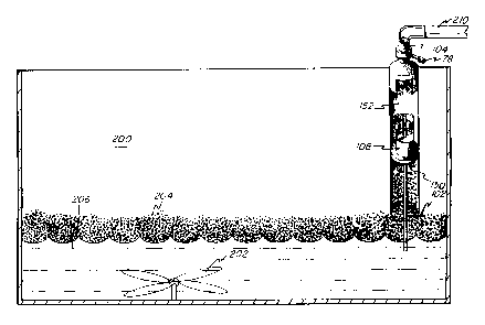
Turning to figure 6 of the drawings, there is shown deinking cell 200
of the type normally encountered in deinking processes. As shown, the cell
includes
an agitator 202 to promote air bubble formation. The ink particles are floated
in the
form of a dense foamy mass 204 atop the recycle pulp slurry 206. The separator
50
is spaced over the foam 204. A suction line 210 is connected to the outlet 104
of the
separator. In this embodiment, the air straightening baffle normally
positioned
adjacent the separator inlet is omitted. It is noted that although only one
separator 50
is depicted in the drawings, a bank or plurality of the same may actually be
employed
in conjunction with a deinking cell.
CA 02379310 2002-O1-10
WO 01/03803 _10_ PCT/US00/18964
In operation, the vacuum drawn through the lime 210 picks the dense
mass 204 off the top of the recycle pulp slurry. The foamy mass 204 enters the
first
cyclonic zone 150 where it is subjected to a preliminary separation, then
moving
downstream through the vanes and into the second cyclonic action zone 152. The
ink particles are lower in specific gravity than the liquid so the cyclonic
action causes
same to be separated and removed through line 210.
While the form of apparatus herein described constitutes a preferred
embodiment of this invention, it is to be understood that the invention is not
limited
to this precise form of apparatus, and that changes may be made therein
without
departing from the scope of the invention which is defined in the appended
claims.