Note: Descriptions are shown in the official language in which they were submitted.
CA 02379669 2002-01-16
WO 01/05519 PCT/NZOO/00127
-1-
Photo-Luminescent Pigment Application
Field of the Invention
The invention relates to a method and apparatus for applying photo-luminescent
pigment to a substrate surface, more particularly for applying photo-
luminescent
pigment to aluminium or other metal strips used, for example, as stair
nosings. The
invention also relates to a product produced by said method and apparatus.
Background to the Invention
Low level floor or walkway lighting is commonly used in such places as picture
theatres, sports arenas and aircraft as both a courtesy and safety feature for
patrons
or passengers. This lighting often takes the form of an electrical or
electronic lighting
means in or on the floor along either side of a walkway or across the nosing
of stairs.
Low level floor lighting is particularly important in picture theatres and
sports arenas
where patrons may be required to negotiate steps in aisles when only low
levels of
ambient light are present, or in stairwells of buifdings during an emergency
when
there may be failure of the main lighting source.
Known methods of floor lighting using electrical or electronic means have a
disadvantage because they require electrical wiring to be run to areas where
access
for the wiring may be limited. They are also prone to failure during failure
of the
main power supply. Additionally, the electronic lighting means are often of a
low
voltage type requiring some form of voltage reduction means such as an
inverter,
converter, or transformer. Not only does addition of this equipment add to the
CA 02379669 2002-01-16
WO 01/05519 PCT/NZOO/00127
2-
complexity and cost of the installation but also provides for additional modes
of
failure.
It is known to apply a photo-luminescent pigment to a rope, tape or fabric.
This
photo-luminescent pigment is stimulated by visible light and remains
luminescent for
a considerable period after the light source is removed. The problem with tape
or
fabric impregnated with pigment is that lacks durability for heavy wear areas
such as
walkways or stairs.
Photo-luminescent pigment has been sprayed onto more durable substrate
surfaces
such as aluminium or metal strips or extrusions. Once the spray has dried, it
is
ground to provide a smooth finished surface. This overcomes the abovementioned
problems associated with heavy wear areas, but considerable pigment is wasted
during the spraying and grinding process.
Accordingly it is an object of the present invention to provide a method and
apparatus for applying photo-luminescence pigment to a substrate which avoids
or
overcomes some of the abovementioned disadvantages, or which at least provides
the public with a useful choice.
CA 02379669 2002-01-16
WO 01/05519 PCT/NZOO/00127
-3-
Summary of the invention
According to a first aspect of the invention there is provided a method of
applying
photo-luminescent pigment to a substrate, said method including:
preparing a dry powder formulation comprising, at least, a photo-luminescent
pigment and a carrier/fixer;
depositing the dry powder formulation onto a substrate surface;
heating the dry powder formulation to fuse it to the substrate surface.
Preferably the substrate surface has depressions or channels adapted to
receive the
dry powder formulation.
Preferably a light reflecting layer is applied to the substrate surface before
depositing
the dry powder formulation.
Preferably the volume ratio of photo-luminescent =pigment to carrier/fixer in
the dry
powder formulation is such that the fused material exhibits substantially the
same
strength and durability properties of the carrier/fixer, while still
exhibiting the photo-
luminescent properties of the pigment. More preferably the volume ratio is
substantially in the range of 1 % to 35% photo-luminescent pigment to
carrier/fixer.
Preferably the dry powered formulation may be heated to between,
substantially, 160
to 210 degrees centigrade, or to a temperature recommended by the manufacturer
of
CA 02379669 2002 oi i7
PCT/NZ00/00127
Received 28 May 2001
-a-
the carrier/fixer, for approximately 10 to 20 minutes or until the formulation
is
molten. The molten formulation may be cooled after heating.
Preferably the carrier/fixer is a heat curable polymer.
6
Preferably the dry powder formulation may include small quantities of
additives, such
as a de-gassing additive, to ensure a smooth surface finish.
Preferably the substrate is stamped, extruded or milled aluminium or metal,
I p
According to a second aspect of the invention there is provided an apparatus
for
applying photo-luminescent pigment to a substrate, said apparatus including:
a hopper adapted to contain a dry powder formulation;
one or more orifices adapted to allow transfer of the dry powder formulation
15 from the hopper to a substrate surface;
a guide rail system for locating the substrate surface in both a fixed
horizontal
plane and a fixed vertical plane below the hopper and orifice; and
a heat-curing system for providing enough heat to turn the dry powder
formulation into a molten mix.
Preferably the apparatus also includes a cooling system to cool the molten
mix.
AMENDED SHEET
jPbAJr%U
CA 02379669 2002-01-16
WO 01/05519 PCT/NZ00/00127
-5-
Preferably the apparatus also includes a drive system to move the substrate
through
the apparatus.
Preferably the apparatus includes a support roller mounted directly beneath
the
orifice(s) and hopper to support the substrate.
Preferably the apparatus includes an adjustable mounting bracket adapted to
enable
the hopper to be located in the correct position so that the orifice(s) lines
up with the
substrate.
Preferably the orifice is adapted to communicate snugly with the substrate
surface
such that the dry powder formulation is deposited substantially only where
required.
Preferably the apparatus includes a mechanism for tapping the hopper so that
any
rat-holes in the dry powder formulation are re-filled.
Preferably the apparatus includes a brush mounted below the roller, and with
its
bristles in contact with the roller, so that any powder that falls onto the
roller is
subsequently brushed off.
The heat-curing system may be an oven. Optionally, the heat-curing system may
be
a continuous oven process, and in one embodiment may include infra-red heating
elements.
CA 02379669 2002-01-16
WO 01/05519 PCT/NZ00/00127
-6-
Preferably the apparatus includes an automatic loading and unloading means at
each
end thereof.
The invention also provides for a product when produced according to the
process, or
by an apparatus, herebefore defined.
Further aspects of the invention will become apparent from the following
description
which is given by way of example only.
Brief Description of the Drawings
An example of the invention will now be described with reference to the
accompanying drawings in which:
FIGURE 1: illustrates a perspective cross section view through a hopper
according to the invention; and
FIGURE 2: illustrates an elevation view of the hopper and a feed table; and,
FIGURE 3: illustrates a schematic overview of one embodiment of an
apparatus according to the invention.
Description of the Invention
The invention provides for a method and apparatus for applying photo
luminescent
pigment, which is stimulated by UV and visible light and will remain
illuminated for a
period after the light source is removed, to a substrate such as aluminium or
metal
strips. The resulting substrate can be used to provide floor, stair or other
courtesy or
emergency lighting in public areas.
CA 02379669 2002-01-16
WO 01/05519 PCT/NZ00/00127
-7-
The process involves filling depressions or channels in a substrate material
(typically,
but not exclusively, an aluminium extrusion or stamped or milled sheet of
aluminium)
with a dry powder formulation that contains a photo luminescent pigment; a
carrier/fixer (typically a heat curable polymer); and preferably small
quantities of
additives (such as a flow additive and/or de-gassing additive) that improve
the melt
properties of the mix and ensure a smooth surface finish. Sufficient heat is
applied
to the combined formulation to melt and cure it, and when cooled it fuses to
itself
and to the substrate.
In order to improve the effectiveness of the photo-luminescent formulation a
light
reflective layer can be applied to the substrate before depositing the
formulation.
The depressions or channels in the substrate are filled up with the dry powder
formulation to be level with the top surface of the substrate material. When
the
formulation becomes molten the air between the particles is expelled and the
subsequently fused material forms a thick film that smoothly covers both the
horizontal and vertical surfaces of the depressions or channels in the
substrate.
Because the surface of the fused formulation is lower than the highest point
of the
depressions or channels it is protected from wear and is suited to use in
floor
illumination situations.
While a number of products suitable for such a photo-luminescent formulation
may be
apparent to a skilled addressee, the products used in the current invention
are
CA 02379669 2002-01-16
WO 01/05519 PCT/NZ00/00127
8-
LUMINOVA, a photo-luminescent pigment from Nemoto Japan; and TPE, a
carrier/fixer produced by Dulux New Zealand. The flow and de-gassing additives
are
also produced by Dulux New Zealand.
The ratio of photo-luminescent pigment to carrier/fixer in the dry powder
formulation
is dependent on the intensity and duration of illumination desired. If greater
intensity
and duration of illumination is desired, more pigment is added. A typical
formulation
will contain between 30% and 60% photo luminescent pigment powder by weight.
However, because the specific gravity of the powder is typically 3-4 times
greater
than the rest of the dry powder formulation, the photo luminescent pigment
volume
ratio is typically in the range 10% to 30%.
Because the photo-luminescent pigment makes up a relatively small part of the
total
volume of the fused material the fused material exhibits substantially the
same
strength and durability properties that the carrier/fixer would have without
the
inclusion of the photo luminescent pigment, but it also has the added property
of
being photo-luminescent. Success has been achieved with volume ratios between
1 % and 35% photo-luminescent pigment.
2o The principle of the process is to pass the substrate material, with the
channels or
depressions facing upwards, below a hopper which is filled with the dry powder
formulation. The hopper has one or more bottom orifices which is shaped so
that the
dry powder formulation will fall under its own weight into the channels or
depressions and will not spill on either side of the substrate. As the
substrate passes
CA 02379669 2002-01-16
WO 01/05519 PCT/NZ00/00127
-9-
under the hopper the lower surface of the bottom orifice(s) wipe the top
surface of
the substrate material clean so that the only dry powder formulation that is
removed
from the hopper is that which fills the channels or depressions. The channels
or
depressions are filled to be level with the top surface of the substrate. Heat
is then
applied to cure the dry powder formulation. After heating the formulation may
be
cooled.
Individual pieces of the substrate material are successively passed underneath
the
hopper in such a way that no substantial quantities of the dry powder
formulation fall
between the tail end of one piece and the lead edge of the subsequent piece.
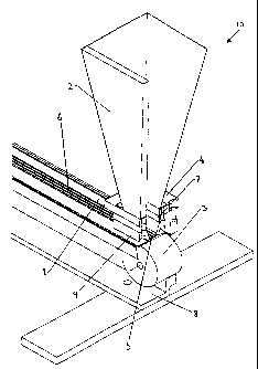
Figures 1 and 2 illustrate, in detail, the hopper section 10 of an apparatus
for
applying photo luminescent material to a substrate. Figure 3 illustrates a
schematic
overview (not to scale) of the whole apparatus, each aspect of which will now
be
described.
The apparatus includes a guide rail system 8 for locating the individual
substrate
pieces, in this case aluminium extrusion 1, in both a fixed horizontal plane
and a fixed
vertical plane.
A drive system is used to push individual substrate pieces passed (below) a
hopper 2.
This drive system may be a human operator, or it may be a system of motorised
rollers 11 that engage with one or two faces of the individual substrate
pieces. Also,
support roller 3 may be motorised to drive the extrusion 1 below hopper 2. In
an
CA 02379669 2002-01-16
WO 01/05519 PCT/NZ00/00127
-10-
automated embodiment of the apparatus the motorised rollers 11 and 3 may be
operated from a variable speed motor drive which may interface with a
controller.
The hopper section 10 comprises the hopper 2, preferably with steep sides to
avoid
build-up of product, that might hold typically, but not exclusively, 1-1.5 kg
of dry
powder formulation. The hopper 2 shown in Figure 1 is cut-away for
illustration
purposes.
An adjustable mounting bracket 4 may also be included to enable the hopper 2
to be
located in the. correct position so that a bottom orifice 5 lines up with the
channels or
depressions 6 in the extrusion 1. Orifice 5 may be formed in a die 9, which is
adapted to suit the extrusion 1 being used. The die 9 would butt snugly over
extrusion 1 so that no formula was spilled or wasted. Various dies may be
interchangeable to provide for different substrates. The dies may have more
than
orifice - for example a two orifice die for a two channel or depression
substrate.
There is a compressible foam rubber insert 7 between the hopper body 1 and the
bottom orifice 5, which suspends the bottom orifice 5 in such a way that it
will still
seal against the extrusion 1 even if the extrusion 1 is not perfectly lined up
with the
hopper 2.
A support roller 3 mounted directly beneath the bottom orifice 5 of the hopper
2 to
support the extrusion 1 without imposing excessive friction. This allows the
extrusions 1 to be readily moved through the system. Roller 3 may be motorised
but
CA 02379669 2002-01-16
WO 01/05519 PCT/NZ00/00127
- 11 -
this is not essential as its main function is to hold the extrusion up to the
orifice 5. A
bristle brush (not shown) may be mounted directly below the roller 3, with its
bristles
in contact with the roller, so that any powder that falls onto the roller is
subsequently
brushed off and will not to build up on the roller 3.
A mechanism (not shown) for tapping the hopper 2 at regular intervals can be
provided so that any "rat-holes" in the dry power are re-filled. Typically the
tapping
action will occur once every 30-60 seconds of operation, which is not enough
to
allow the different components of the dry powder formulation to separate
substantially. In its simplest form this "mechanism" may in fact be the hand
of a
human operator, but ideally this function is carried out by a solenoid or air
actuated
arm. Alternatively an auger or screw may be included which either continuously
or
intermittently "mixes" the formula, thereby filling any "rat holes".
The apparatus also includes a heat-curing system, for example an oven, 12 to
provide
enough heat to melt and cure the dry powder formulation, and bond it to the
substrate. This could be an oven with a rack system. After the individual
substrate
pieces have had their channels or depressions filled with the dry powder
formulation
they are loaded by hand onto the racks. When the racks are full the racks are
placed
in the oven for the required time. Using this system a typical curing cycle
may be
10-20 minutes at 160 C to 200 C.
In an automated apparatus the oven would most preferably be a continuous
tunnel
process so that after the individual substrate pieces have had their channels
or
CA 02379669 2002-01-16
WO 01/05519 PCT/NZ00/00127
-12-
depressions filled with the dry powder formulation they immediately enter a
curing
tunnel 12 that rapidly heats them to typically 160 C to 200 C for a sufficient
time
to turn the dry powder formulation into a molten mix and bond it to the
substrate.
The individual substrate pieces then emerge from the opposite end of the
tunnel. A
cooling tunnel 13 may also be provided.
The curing tunnel could be either a hot-air type oven or an infra-red oven. At
present
the applicant has found that the hot-air type oven produces the best result.
However, infra-red ovens provide a much faster and more direct heating method.
The problem with infra-red ovens is that the rapid localised heating causes
distortion
of the substrate material. The degree of distortion is dependent on the form
and type
of substrate material. It is envisaged that with improvements in infra-red
heating
technology and substrate materials this will become the preferred method.
The above-described system may be fully automated if required by the use of
automatic loading and unloading magazines at each end, 14 and 15 respectively,
of
the production line 8. Automation of such a system, using for example a
programmable logic controller or PC based control system, is well within the
capability of one skilled in the art and will not be discussed further.
The photo-luminescent pigment application process will now be described, by
way
for example only, to illustrate the method of the invention.
CA 02379669 2002-01-16
WO 01/05519 PCT/NZ00/00127
- 13-
A representative piece of substrate is placed on the guide rail close to the
empty
hopper, then passed into the gap between the bottom orifice of the hopper and
the
support roller. The position of the hopper assembly is adjusted as necessary
to
ensure that the bottom orifice lines up with the channels or depressions in
the
substrate, and there are no gaps to either side that would let powder escape.
The
hopper is then filled with a thoroughly mixed quantity of the dry powder
formulation.
The first piece of "production" substrate is then placed on the guide rail,
immediately
behind the representative piece of substrate, and moved towards the hopper
assembly. In this way it pushes the representative piece of substrate through
and
passed the hopper assembly and onto the guide rail on the other side of the
hopper
assembly. The representative piece of substrate can subsequently have the
powder
that has been applied to it removed by a vacuum cleaning head and then the
substrate can be reused as a plug for the hopper's bottom orifice whenever
production is halted.
Before the first piece of production substrate is pushed right through the
hopper
assembly the second piece of production substrate is picked up off a magazine
and
placed on the guide rail immediately behind the first piece of production
substrate.
Once the first piece of production substrate is away from the hopper assembly
it can
be taken off the guide rail and placed on racks ready for oven curing.
The above step is then repeated until the oven racks are full. The racks are
placed in
the oven for the required curing cycle, then removed from the oven and allowed
to
cool before final inspection and packaging.
CA 02379669 2002-01-17 PCTlNZ00/00127
Received 15 February 2001
- 14-
At regular intervals as required the hopper is tapped to remove "rat-holes" in
the
powder and the hopper is refilled with thoroughly mixed dry powder
formulation.
When the production run has finished the representative piece of substrate can
be
reused as a plug for the hopper's bottom orifice and finally any left-over
powder can
be removed from the hopper.
It can readily be seen that whereas the above description describes the method
of
operation for a non-mechanised form of the apparatus the process can readily
be
automated using the optional automating equipment described above so that the
process becomes either semi-automatic or fully automatic. Such automation
would
be well within the capabilities of the nominally skilled person.
Photo-luminescent formulation can be applied, by the above-described method,
to
articles having channelled surfaces for use in such places as picture
theatres,
sporting arenas, aircraft aisles and building corridors/stairways where the
illumination
can be adapted in guiding people to an exit in an emergency or when normal
lighting
fails. Two examples of articles are step nosings and handrails.
A step nosing is the angled member across the front edge of a step. The
current
invention can be used to deposit photo-luminescent formulation within
castellations,
or recessed channels, in the top surface of a step nosing. This results in a
step
nosing which is luminescent for an extended period after ambient illumination
is
AMENDED SHEET
PEAlAV
CA 02379669 2002-01-17 pCT/NZ00/00127
Received 15 February 2001
-15-
switched off, and hence helps maintain the safety of spectator areas in
picture
theatres, sporting arenas and the like in low light situations. The extrusion
1
illustrated in Figure 1 is a step nosing with castellations, or recessed
channels, 6 in
its top surface.
In a further embodiment the photo-luminescent formulation might be deposited
within
castetlations, or recessed channels, of a insert strip which engages with the
top
surface of a step nosing. This would allow the photo-luminescent insert strip
to be
replaced without replacing the whole step noising.
Photo-luminescent formulation could also be deposit within castellations, or
recessed
channels, on stair and other handrails. The castellations, or recessed
channels,
carrying the photo-luminescent formulation may be part of a replaceable insert
strip.
Where in the foregoing description reference has been made to integers or
elements
having known equivalents, then such equivalents are herein included as if
individually
set forth.
Particular examples of the invention have been described and it is envisaged
that
improvements and modifications can take place without departing from the scope
of
the appended claims.
AMENDED SHEET
~AIAI~