Language selection

Search

Patent 2379724 Summary

Third-party information liability

Some of the information on this Web page has been provided by external sources. The Government of Canada is not responsible for the accuracy, reliability or currency of the information supplied by external sources. Users wishing to rely upon this information should consult directly with the source of the information. Content provided by external sources is not subject to official languages, privacy and accessibility requirements.

Claims and Abstract availability

Any discrepancies in the text and image of the Claims and Abstract are due to differing posting times. Text of the Claims and Abstract are posted:

  • At the time the application is open to public inspection;
  • At the time of issue of the patent (grant).
(12) Patent Application: (11) CA 2379724
(54) English Title: TOOL FOR INSERTING A THREADED PART INTO AN AREA DIFFICULT TO ACCESS
(54) French Title: OUTIL SERVANT A PLACER UNE PARTIE FILETEE DANS UNE ZONE DIFFICILEMENT ACCESSIBLE
Status: Deemed Abandoned and Beyond the Period of Reinstatement - Pending Response to Notice of Disregarded Communication
Bibliographic Data
(51) International Patent Classification (IPC):
  • B25B 13/48 (2006.01)
  • B25B 9/00 (2006.01)
  • B25B 23/00 (2006.01)
(72) Inventors :
  • FEILNER, MARCUS (Germany)
(73) Owners :
  • ERICH FEILNER
(71) Applicants :
  • ERICH FEILNER (Germany)
(74) Agent: MARKS & CLERK
(74) Associate agent:
(45) Issued:
(86) PCT Filing Date: 2000-08-02
(87) Open to Public Inspection: 2001-02-08
Availability of licence: N/A
Dedicated to the Public: N/A
(25) Language of filing: English

Patent Cooperation Treaty (PCT): Yes
(86) PCT Filing Number: PCT/DE2000/002558
(87) International Publication Number: WO 2001008851
(85) National Entry: 2002-02-04

(30) Application Priority Data:
Application No. Country/Territory Date
299 13 230.7 (Germany) 1999-08-03

Abstracts

English Abstract


A tool for inserting a threaded part (1), comprising a fixing head (2) that
holds the
threaded part (1) such that it cannot turn and is connected to the one end of
a guide rod
(3) while the other end projects from the area difficult to access. The object
of inserting a
threaded part, for example a nut, into an area difficult to access is solved
in that the fixing
head (2) is provided with a grooved recess (5) that extends at a right angle
to its
longitudinal axis and holds the threaded part (1) with frictional force, at
least in some
sections, between the two opposite-arranged, parallel surfaces (6), extending
in a
direction where the thread axis is at a right angle to the longitudinal axis
of the fixing
head (2).


French Abstract

L'invention concerne un outil servant à placer une partie filetée (1) dans une zone difficilement accessible et comportant une tête de maintien (2) qui reçoit la partie filetée (1), empêche sa torsion et peut être reliée à une extrémité à une barre de guidage (3) dont l'autre extrémité fait saillie hors de la zone difficilement accessible. L'invention vise à permettre le placement de la partie filetée, par exemple d'un écrou, dans une zone difficilement accessible. A cet effet, la tête de maintien (2) présente un évidement (5) en forme d'encoche et à angle droit par rapport à son axe longitudinal, qui reçoit en liaison de force la partie filetée (1) au moins partiellement entre ses deux surfaces parallèles opposées (6), dans une direction telle que l'axe du filetage est perpendiculaire à l'axe longitudinal de la tête de maintien (2).

Claims

Note: Claims are shown in the official language in which they were submitted.

PATENT CLAIMS
1. A tool for inserting a threaded part (1) into an area difficult to access,
said tool
comprising a fixing head (2) for holding the threaded part ( 1 ) such that it
cannot
turn, which head can be connected to the one end of a guide rod (3) while the
other end projects from the area difficult to access, wherein the fixing head
(2) is
provided with a grooved recess (5) that extends at a right angle to its
longitudinal
axis and holds the threaded part (1) with frictional force, at least in some
sections,
between its two opposite-arranged, parallel surfaces (6), extending in a
direction
where the thread axis is at a right angle to the longitudinal axis of the
fixing head
(2),
characterized in that the fixing head (2) can be connected via a connecting
mechanism (8) to one end of the guide rod (3) and can thus be replaced with
another, differently dimensioned fixing head (2).
2. A tool according to claim 1, characterized in that the two opposite-
arranged,
parallel surfaces (6) are provided with at least one spring that holds the
threaded
Part (1).
3. A tool according to one of the claims 1 or 2, characterized in that the
distance
between the two opposite-arranged, parallel surfaces (6) of the recess (5) can
be
changed.
6

4. A tool according to one of the claims 1 to 3, characterized in that the
fixing head
(2) between the parallel surfaces (6) is provided with at least one permanent
magnet (7) that holds the threaded part (1).
5. A tool according to one of the claims 1 to 4, characterized in that the
fixing head
(2) is provided with at least one other permanent magnet (11) on its front,
which
holds the threaded part (1).
6. A tool according to one of the claims 1 to 5, characterized in that the
length of
guide rod (3) can be changed, in particular with tubes (9, 10) that can be
telescopically pushed into each other.
7. A tool according to one of the claims 1 to 6, characterized in that the end
of guide
rod (3), which projects from the area difficult to access, is provided with a
handle
(4) of wood, plastic or rubber or is provided with a layer of one of these
materials.
8. A tool according to one of the claims 1 to 7, characterized in that the
fixing head
(2) and the guide rod (3) have an essentially cylindrical design.
9 A tool according to claim 8, characterized in that the fixing head (2) is
provided
with another recess (12) above and below the grooved recess (5) for
accommodating a threaded part (1), consisting of a nut and connected cylinder-
shaped, curved washer or a corresponding one-piece component.
7

Description

Note: Descriptions are shown in the official language in which they were submitted.


CA 02379724 2002-02-04
DESCRIPTION
Tool for Inserting a Threaded Part into
an Area Difficult to Access
The invention relates to a tool for inserting a threaded part, in particular a
nut, into
an area difficult to access, for example inside a bore in a wooden beam. The
tool consists
of a fixing head that holds the threaded part in such a way that it cannot
turn. The fixing
head can be connected to the one end of a guide rod while the other end
projects from the
area difficult to access.
A tool of this type is known from the US-PS 5,052,253 and is used to guide the
tip of a screwdriver into the slot of a screw, with the aid of a sleeve fitted
over a
screwdriver, and to hold the screw in this position for screwing it into the
thread of a deep
bore. The axis of the screwdriver for this known tool coincides with the axis
of the
screw.
In metal construction and wood construction, the problem frequently arises
that a
screw must be screwed into the thread of a threaded part, for example a nut,
for which the
thread axis is at a right angle to the tool used for inserting the nut.
In those cases, the problem was solved, in particular in metal construction,
by
gluing on or welding on the threaded part of the nut well ahead of time, while
the location
was still accessible.
In the area of wood construction, this problem occurs, for example, if the
rafters
of a roof truss extend into an inside area and are visible there. To screw
these rafters with
the aid of a tensioning connector to a beam supporting the rafters, it must be
accepted that
1

CA 02379724 2002-02-04
the screw head remains visible and can be designed as decorative head, or the
nut remains
visible, so that domed cap nuts must be used. The screw head or nut can also
be
countersunk in the rafter and the remaining hole plugged with a wooden plug.
These
solutions are not very elegant and disturb the view of the otherwise smooth
planes of the
rafters.
To avoid this problem, it is suggested that a bore be drilled from the front
of the
rafter, which is not located on the inside, crosswise to the blind bore for
the threaded part
or the screw to the location where the threaded part or the nut must be
seated.
Unfortunately, however, it is nearly impossible to insert the threaded part or
nut at the
correct location, so that the problem could not be solved so far with this
suggestion.
Thus, it is the object of the invention to create a simple tool, which makes
it
possible to insert a threaded part into which a screw is screwed, for example
a nut having
a thread axis that extends at a right angle to the longitudinal axis of the
tool, into an area
difficult to access.
This object is solved with the features in claim 1 in that the fixing head is
provided with a grooved recess extending at a right angle to its longitudinal
axis, which
holds the threaded part, at least in some sections, such that it is
fractionally clamped
between its two opposite arranged parallel surfaces and the direction for the
thread axis is
at a right angle to the longitudinal axis of the fixing head.
One modification of the invention provides that the two opposite-arranged,
parallel surfaces have at least one spring for holding the threaded part, so
that the
threaded part is held securely inside the fixing head.
2

CA 02379724 2002-02-04
It is furthermore provided that the distance between the opposite-arranged,
parallel surfaces of the recess can be changed to adapt to different
dimensions of the
threaded part.
In order to hold the threaded part securely and easily, the fixing head is
provided
with at least one permanent magnet between the parallel surfaces, wherein at
least one
additional permanent magnet is installed on the front of the fixing head for
extracting a
threaded part or other part.
To be able to use the tool for threaded parts with different dimensions, it is
furthermore provided that the fixing head can be connected via a connecting
mechanism
to the one end of the guide rod and can thus be replaced with another fixing
head of a
different dimension.
The guide rod is designed such that its position can be changed, particularly
with
the aid of telescoping tubes, to allow a maximum number of uses for the guide
rod.
Other advantageous embodiments of the invention are disclosed in the dependent
claims.
The advantages according to the invention are, in particular, that a threaded
part
can be inserted without problems into an area difficult to access and with the
aid of the
tool, especially a nut having a thread axis that extends at a right angle to
the tool axis.
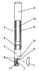
One exemplary embodiment of the invention is shown in the drawing and is
described in further detail in the following. Shown are in:
Figure 1 A view from the side (partial section) of a tool according to the
invention
and next to it, a view from the side of a threaded part.
3

CA 02379724 2002-02-04
Figure 2 A view of the tool front and next to it a side view of the threaded
part.
The tool according to Figure 1 consists of a fixing head 2 for holding a
threaded
part l, such that it cannot turn, which fixing head is connected to the one
end of a guide
rod 3, the other end of which is provided with a handle 4.
The threaded part 1 consists of a square nut to which a curved washer is
welded,
as shown in Figure 2. Thus, it is particularly suitable for use as a
tensioning connector
for connecting rafters of a roof truss to a transverse beam. For this, a bore
is drilled
crosswise to the blind hole bore for the screw from the front of the rafter to
a location
where the nut with curved washer is to be seated.
With the tool according to the invention, the nut can be moved easily to this
location by moving it in the arrow direction (Figures 1 and 2) toward the
fixing head 2
and is held in place by the attractive power of a first permanent magnet 7.
The nut fits
into a recess S and the curved washer into an additional recess 12. After
screwing the
screw of the tensioning connector into the thread of the nut, the fixing head
2 is released
again, so that the tool can be easily pulled from the bore.
The fixing head 2 is provided with a grooved recess 5 that extends crosswise
to its
longitudinal direction and holds the nut between its two opposite-arranged,
parallel
surfaces 6. The nut is held in place by the attractive power of the first
permanent magnet
7. An additional permanent magnet 11 is installed on the front of the fixing
head 2 and is
used, for example, for the easy extraction of a nut that may have been lost in
the blind
hole or the like.
4

CA 02379724 2002-02-04
The fixing head 2 can be connected via a connecting mechanism 8 to the one end
of the guide rod 3 and can thus be exchanged with another fixing head 2 having
a
different dimension.
The length of guide rod 3 can be changed with the aid of two tubes 9, 10 that
can
be pushed telescopically into each other. A sectional view of the outer tube 9
is shown in
Figure 1, while the inner tube 10, which turns into the handle 4, is shown as
a view.
The handle 4 advantageously consists of wood, plastic or rubber or is covered
with a layer of one of these materials, such that it can be handled easily.

Representative Drawing
A single figure which represents the drawing illustrating the invention.
Administrative Status

2024-08-01:As part of the Next Generation Patents (NGP) transition, the Canadian Patents Database (CPD) now contains a more detailed Event History, which replicates the Event Log of our new back-office solution.

Please note that "Inactive:" events refers to events no longer in use in our new back-office solution.

For a clearer understanding of the status of the application/patent presented on this page, the site Disclaimer , as well as the definitions for Patent , Event History , Maintenance Fee  and Payment History  should be consulted.

Event History

Description Date
Application Not Reinstated by Deadline 2006-08-02
Time Limit for Reversal Expired 2006-08-02
Inactive: Abandon-RFE+Late fee unpaid-Correspondence sent 2005-08-02
Deemed Abandoned - Failure to Respond to Maintenance Fee Notice 2005-08-02
Letter Sent 2003-01-10
Inactive: Single transfer 2002-11-06
Inactive: Cover page published 2002-08-02
Inactive: Courtesy letter - Evidence 2002-07-30
Inactive: Notice - National entry - No RFE 2002-07-25
Application Received - PCT 2002-05-07
National Entry Requirements Determined Compliant 2002-02-04
Application Published (Open to Public Inspection) 2001-02-08

Abandonment History

Abandonment Date Reason Reinstatement Date
2005-08-02

Maintenance Fee

The last payment was received on 2004-07-30

Note : If the full payment has not been received on or before the date indicated, a further fee may be required which may be one of the following

  • the reinstatement fee;
  • the late payment fee; or
  • additional fee to reverse deemed expiry.

Please refer to the CIPO Patent Fees web page to see all current fee amounts.

Fee History

Fee Type Anniversary Year Due Date Paid Date
Basic national fee - standard 2002-02-04
MF (application, 2nd anniv.) - standard 02 2002-08-02 2002-02-04
Registration of a document 2002-11-06
MF (application, 3rd anniv.) - standard 03 2003-08-04 2003-07-16
MF (application, 4th anniv.) - standard 04 2004-08-02 2004-07-30
Owners on Record

Note: Records showing the ownership history in alphabetical order.

Current Owners on Record
ERICH FEILNER
Past Owners on Record
MARCUS FEILNER
Past Owners that do not appear in the "Owners on Record" listing will appear in other documentation within the application.
Documents

To view selected files, please enter reCAPTCHA code :


To view images, click a link in the Document Description column. To download the documents, select one or more checkboxes in the first column and then click the "Download Selected in PDF format (Zip Archive)" or the "Download Selected as Single PDF" button.

List of published and non-published patent-specific documents on the CPD .

If you have any difficulty accessing content, you can call the Client Service Centre at 1-866-997-1936 or send them an e-mail at CIPO Client Service Centre.


Document
Description 
Date
(yyyy-mm-dd) 
Number of pages   Size of Image (KB) 
Representative drawing 2002-08-01 1 5
Abstract 2002-02-04 1 19
Claims 2002-02-04 2 65
Drawings 2002-02-04 1 13
Description 2002-02-04 5 175
Cover Page 2002-08-02 1 39
Notice of National Entry 2002-07-25 1 208
Courtesy - Certificate of registration (related document(s)) 2003-01-10 1 106
Reminder - Request for Examination 2005-04-05 1 117
Courtesy - Abandonment Letter (Maintenance Fee) 2005-09-27 1 173
Courtesy - Abandonment Letter (Request for Examination) 2005-10-11 1 167
PCT 2002-02-04 15 561
Correspondence 2002-07-25 1 24
PCT 2002-02-05 5 207