Note: Descriptions are shown in the official language in which they were submitted.
CA 02379728 2002-04-02
TITLE OF THE INVENTION
Detachable Shoulder Rest Apparatus for Telephone Handsets
BACKGROUND OF THE INVENTION
Field of the Invention
s The present invention relates in general to a detachable shoulder rest
apparatus for
use with telephone handsets and, in particular, to a detachable shoulder rest
that utilizes
an attaching mechanism for removably attaching the shoulder rest to a cordless
telephone
or other portable electronic communication device.
Background Art
io Telephone handset shoulder rests are well known in the art. Shoulder rest
attachments have long been an available option to telephone users, since it
has been
deemed desirable to provide a comfortable way of allowing a telephone handset
to rest
between the user's head and shoulder without having to hold onto the handset,
thereby
freeing up both of the user's hands to perform other functions and without
inducing strain
is on the user's neck if forced to cock one's head to retain the handset
between head and
shoulder.
The prior art discloses the use of adhesive for permanently attaching a
shoulder
rest to a telephone handset, and specifically to the rear or outer facing
surface of the
handset. Typically the shoulder rest is sold to the consumer as an accessory
and comes
2o packaged with a strip of double-sided tape carrying the adhesive to glue
the shoulder rest
to the telephone handset. Such shoulder rests were intended for traditional
telephone
handsets that are, via a telephone cord, connected to a telephone base.
i
CA 02379728 2002-04-02
However, as time progresses, the adhesive material begins to lose its ability
to hold
the shoulder rest and telephone handset together. As a result, the shoulder
rest begins to
peal away from the handset, and eventually either falls off or is torn off by
the user. When
the shoulder rest is removed, intentionally or by effect of time and use, a
coat of the
s adhesive material remains on the handset. This remaining adhesive material
is difficult to
remove, and becomes both unsightly and unsanitary.
Additionally, because of constant use, flexible shoulder rests begin to lose
their
ability to return to their original shape. As a result, the shoulder rest
begins to flatten,
causing usage of the shoulder rest to become difficult and uncomfortable.
Since these
to shoulder rests are designed to be permanently affixed to the handset, the
user must, if the
shoulder rest has not yet peeled off, spend the time and energy tearing the
shoulder rest
from the handset and removing the remaining adhesive material. Only then may a
replacement shoulder rest be securely attached.
A permanently adhered shoulder rest is undesirable when a user wishes to take
is advantage of the compact size and intended mobility of a cordless or
portable phone. By
permanently affixing a shoulder rest to cordless or portable telephone
handset, the
phone's inherent advantages are destroyed because the phone becomes bulky and
cumbersome to carry. Additionally, some cordless telephones have keypads
positioned
on the handset where a shoulder rest would be located. Other models of
cordless
2o telephone handsets provide battery compartments through which one can
access the
rechargeable battery to replace it if necessary. A battery compartment door is
often
positioned on the rear facing surface of the cordless handset. An adhesively
mounted
2
CA 02379728 2002-04-02
shoulder rest would restrict or totally preclude access to the battery by
effectively gluing it
shut. In those situations a permanently attached shoulder rest is not a viable
option.
It would be desirable to provide for a shoulder rest apparatus that may be
used with
cordless telephones, or other portable electronic communication devices, which
is readily
detachable from the telephone handset.
These and other objects of the present invention will become apparent to those
of
ordinary skill in the art in light of the present specifications, drawings and
claims.
CA 02379728 2002-04-02
SUMMARY OF THE INVENTION
The present invention is directed to a detachable shoulder rest apparatus for
use
with a telephone handset having one or more positions on the exterior of the
telephone
handset housing capable for accepting removable placement of telephone
accessories.
s The detachable shoulder rest comprises of a body portion configured to rest
against the
user's shoulder for supporting the telephone handset between the user's
shoulder and
head and at least one attachment member for engaging with the telephone
handset to
removably attach the body portion to the exterior of the telephone handset.
In a preferred embodiment, the body portion may comprise a contoured wedge to
io substantially conform to the shape of the user's shoulder. In addition, the
body portion
may comprise a substantially rigid material or a deformable material capable
of conforming
to the shape of the user's shoulder.
In another preferred embodiment, the at least one attachment member comprises
a
plurality of arms extending from the body portion and configured so as to
engage at least
is one slot or recess located on the telephone handset. In yet another
embodiment, the at
least one attachment member comprises at least one hook member configured so
as to
engage at least one slot or aperture located on the telephone handset. in
stilt another
embodiment, the at least one attachment member comprises at least one slot or
aperture
configured so as to engage at least one projection or protrusion located on
the telephone
2o handset.
4
CA 02379728 2002-04-02
Another preferred embodiment of the invention further comprises a base portion
joining the body portion to the at least one attachment member. In this
embodiment, the
base portion and body portion may be separable from one another.
CA 02379728 2002-04-02
BRIEF DESCRIPTION OF THE DRAWINGS
FIG. 1 is a perspective view of a detachable shoulder rest apparatus according
to a
preferred embodiment of the present invention, showing the shoulder rest
apparatus
detached from the telephone handset;
s FIG. 2 is a perspective view of the detachable shoulder rest apparatus shown
in
Fig. 1, showing the shoulder rest apparatus attached to the telephone handset;
FIG. 3 is a cross-sectional view of the detachable shoulder rest apparatus
shown in
Fig. 1, showing the shoulder rest apparatus attached to the telephone handset
by means
of a plurality of arms extending from the body portion of the shoulder rest
apparatus
io engaging a plurality of recesses located on the telephone handset;
FIG. 4 is a cross-sectional view of another preferred embodiment of the
invention,
showing the body portion and attachment member portions of the shoulder rest
apparatus
as combined into a single piece;
FIG. 5 is a perspective view of another embodiment of the invention, showing
the
is attachment members as hook members attached to the bottom of the body
portion of the
shoulder rest apparatus, along with the slots adapted for receiving the hook
members
located on the back of the telephone handset.
6
CA 02379728 2002-04-02
DETAILED DESCRIPTION OF THE INVENTION
While this invention is susceptible of embodiment in many different forms,
there are
shown in the drawings and will be described in detail herein several specific
embodiments,
with the understanding that the present disclosure is to be considered as an
s exemplification of the principle of the invention and is not intended to
limit the invention to
embodiments illustrated.
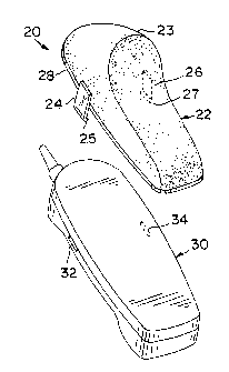
Detachable shoulder rest apparatus 20 is shown in Figs. 1-3 as including body
portion 22, arms 24 and 26, and base portion 28. In this embodiment, shoulder
rest
apparatus 20 is primarily designed for use with cordless telephone handsets
incorporating
to fittings or recesses to accommodate the removable placement of external
telephone
accessories, such as a belt clip, although it may also be used with
conventional cellular
telephone handsets adapted in a similar manner. Telephone handset 30 is shown
in Figs.
1-3 as including slots 32 and 34 for the removable placement of external
telephone
accessories, as described below. In the embodiment illustrated, slots 32 and
34 are
is incorporated into the mold line which defines the joining of the upper and
lower halves of
telephone handset housing. Alternatively, slots 32 and 34 could be formed into
other
locations along the sides of telephone handset 30.
Body portion 22 is shown as comprising a contoured wedge shape 23, which
substantially conforms to the shape of a user's shoulder. Body portion 22 may
be made
2o from either a deformable material or a rigid material and may be formed to
toke on other
shapes which serve to facilitate the comfortable holding of the telephone
handset 30 when
supported by the user's shoulder.
CA 02379728 2002-04-02
Arms 24 and 26 are shown in Fig. 3 as comprising an "L" shape, with tips 25
and 27
that are perpendicular to the remainder of arms 24 and 26. Arms 24 and 26 are
preferably
constructed of plastic or other similar flexible material which will allow
arms 24 and 26 to
bend outward and then return to their original position when a bending force
is removed so
s as to facilitate a friction fit between shoulder rest apparatus 20 and phone
30.
Shoulder rest apparatus 20 is shown in Fig. 1 separated from telephone handset
30. The user joins shoulder rest apparatus 20 and telephone handset 30 by
positioning
shoulder rest apparatus 20 directly above telephone handset 30 such that arms
24 and 26
encounter the sides of telephone handset 30 and are bent outward slightly. The
user then
io pushes shoulder rest apparatus 20 and telephone handset 30 together, so
that tips 25 and
27 encounter slots 32 and 34, allowing arms 24 and 26 to return to their
original position
such that tips 25 and 27 snap into and engage slots 32 and 34. This attached
configuration is shown in Figs. 2 and 3.
Once shoulder rest apparatus 20 and telephone handset 30 are attached, they
will
is remain so by the force exerted by arms 24 and 26 preventing accidental
separation from
one another due to the fact that tips 25 and 27 are constrained by the walls
of slots 32 and
34. In order to remove shoulder rest apparatus 20 from telephone handset 30,
the user
bends arms 24 and 26 outward slightly so that tips 25 and 27 are removed from
slots 32
and 34, and then pulls shoulder apparatus 20 away from telephone handset 30.
2o In the illustrated embodiment, base portion 28 is shown as a substantially
flat, rigid
member with body portion 22 affixed to base portion 28. However, it is
contemplated that
body portion 22 and base portion 28 may be constructed so as to be separable,
allowing
s
CA 02379728 2002-04-02
the user to remove body portion 22 while leaving base portion 28 attached to
the
telephone handset. This allows the user to replace body portion 22 without
replacing the
whole apparatus if, for example, body 22 should tear, become discolored or
otherwise
need replacement. Similarly, base portion 28 can be replaced should either of
arms 24
s and 26 be inadvertently broken. This also allows the user to attach other
telephone
accessories, such as belt clips, to the telephone handset by removably
attaching such
items to base portion 28, rather than to the handset 30 itself.
In another embodiment of the invention, detachable shoulder rest apparatus 20'
is
shown in Fig.4 as comprising body portion 40 and arms 42 and 44. In this
embodiment,
io shoulder rest apparatus 20' does not contain a base portion. Rather, arms
42 and 44 are
an integral part of body portion 40. In this embodiment the entire integrated
assembly
could be fabricated of a rigid or semi-rigid material, so long as tips 25 and
27 are carried
by arms 24 and 26 are retained in slots 32 and 34.
In still another embodiment of the invention, detachable shoulder rest
apparatus 20"
is is shown in Fig. 5 as comprising body portion 50 and arm and hook members
52 and 54.
Telephone handset 56 is shown as comprising slots 58 and 60. ~~ook members 52
and 54
are preferably made of plastic or a similar flexible material such that hook
members 52 and
54 are capable of bending outward slightly during attachment to telephone
handset 56 and
then returning to their original position.
2o In this embodiment, shoulder rest apparatus 20" and telephone handset 56
are
joined by positioning shoulder rest apparatus 20" above telephone handset 56
such that
hook members 52 and 54 are aligned with slots 58 and 60. The user then pushes
9
CA 02379728 2002-04-02
shoulder rest apparatus 20" and telephone handset 56 together, such that hook
members
52 and 54 are inserted into slots 58 and 60. After such attachment, hook
members 52 and
54 are constrained within slots 58 and 60, preventing accidental separation of
shoulder
rest apparatus 20" and telephone handset 56. Shoulder rest apparatus 20" may
be
s detached by pulling shoulder rest apparatus 20" away from telephone handset
56, thus
causing hook members 52 and 54 to bend inward slightly and disengage. The user
can
then easily remove shoulder rest apparatus 20".
The foregoing description and drawings are merely to explain and illustrate
the
inventions and the invention is not limited thereto except insofar as the
independent claims
io are so limited, as those skilled in the art with the present disclosure
before them will be
able to make modifications and variations therein without departing from the
scope of the
invention.
io