Note: Descriptions are shown in the official language in which they were submitted.
CA 02380127 2002-04-04
t ,t
' SNAP-ON SIDE GUARDS
FIELD OF INVENTION
This invention relates to conveyor belts and, more
particularly, to modular plastic conveyor belts formed
of rows of plastic belt modules pivotally interlinked by
transverse pivot rods.
BACKGROUND OF THE INVENTTON
Because they do not corrode, are light weight, and
are easy to clean, unlike metal conveyor belts, plastic
conveyor belts are used widely, especially in conveying
food products. Modular plastic conveyor belts are made
up of molded plastic modular links, or belt modules,
that can be arranged side by side in rows of selectable
width. A series of spaced apart link ends extending
from each side of the modules include aligned apertures
to accommodate a pivot rod. The link ends along one end
of a row of modules are interconnected with the link
ends of an adjacent row. A pivot rod journaled in the
aligned apertures of the side-by-side and end-to-end
connected modules forms a hinge between adjacent rows.
Rows of belt modules are connected together to form an
endless conveyor belt capable of articulating about a
drive sprocket.
In many industrial applications, conveyor belts are
used to carry products along paths including curved
segments. Belts capable of flexing sidewise to follow
curved paths are referred~to as side-flexing, turn, or
radius belts. As a radius belt negotiates a turn, the
CA 02380127 2002-04-04
_ v
.. . _ 2 _
belt must be able to fan out because the edge of the
belt at the outside of the turn follows a longer path
than the edge at the inside of the turn. In order to
fan.out, a modular plastic radius belt typically has
provisions that allow it to collapse at the inside of a
turn or to spread out at the outside of the turn.
Apertures slotted in the direction of travel of the
belt are commonly provided in the link ends on at least
one side of the modules to facilitate the collapsing and
spreading of the belt.
It has been known to provide radius belts with side
guards to prevent transported articles from falling off
of the conveyor belt. The conventional arrangement for
attaching the side guards to radius belts has been to
I5 hold the side guard between link ends by attachment of
one end of the side guard to one of the link ends and by
attaching the opposite end of the side guard to the
pivot rod adjacent to the link end. This solution has
the disadvantage that it may significantly hinder the
collapsing of the modules in the curve.
What is needed is a snap-on side guard for a
modular radius conveyor belt that does not interfere
with the collapsing of the modules and that can be
easily assembled and disassembled for cleaning.
SUr~ll~IARY OF THE INVENTION
The present invention meets the above-described
CA 02380127 2002-04-04
. v a
- 3 -
need by providing an endless conveyor belt formed of
plastic belt modules and capable of following a curved
path. The modules include first and second module
surfaces, i.e., a top, product-conveying surface and a
bottom, sprocket-driven surface. An intermediate
section extends across the width of each module
transverse to the direction of belt travel.
A plurality of snap-on side guards are mounted in
vertical openings disposed in the belt modules. Each
side guard includes a central post having opposed wings
extending in a forwardiy and a rearwardly direction
along the direction of conveyor belt travel. The wings
are staggered in the lateral direction so that the
forward wing of a first side guard overlaps with the
rearward wing of an immediately adjacent second side
guard.
Accordingly, the side guards do not interfere with
the collapsing of the belt around turns because they are
not attached to the pivot rods. Also, because the wings
on adjacent modules are offset laterally they are
capable of moving relative to one another without
interference.
BRIEF DESCRIPTION OF THE DRAWINGS
The invention is illustrated in the drawings in which
like reference characters designate the same or similar
parts throughout the figures of which:
CA 02380127 2002-04-04
_ 4 _
Fig. 1 is a top plan view of a radius conveyor belt
with the snap-on side guards of the present invention
and with a portion of the belt modules cutaway;
Fig. lA is a detailed top plan view of the cutaway
portion shown in Fig. 1;
Fig. 2 is a partial side elevational view of the
belt and snap-on side guards shown in Fig. 1;
Fig. 3 is a sectional view taken along lines 3-3 of
Fig. 2;
Fig. 4 is a front elevational view of a snap-on
side guard of the present invention;
Fig. 5 is a top plan view of the snap-on side guard
of Fig . 4 ;
Fig. 6 is a side elevational view of the snap-on
side guard of Fig. 4;
Fig. 7 is a perspective view of the snap-on side
guard of Fig. 4; and,
Fig. 8 is a top plan view of a radius conveyor
belt, which is provided with the snap-on side guards of
the present invention, as it rounds a curve.
DESCRIPTION OF THE PREFERRED EMBODIMENTS
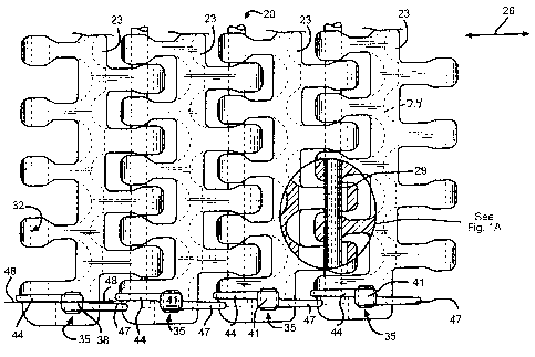
Referring now to Figs. 1-8 and initially to Figs. 1
and lA, a portion of a modular belt 20 of the present
invention is shown. The portion of the modular belt 20
shown is formed from molded plastic modules 23. For
reference, the direction of belt travel is indicated by
CA 02380127 2004-09-23
- 5 -
arrow 26. A plurality of pivot rods 29 connect adjacent belt
modules 23 by passing through openings 32 in the modules 23
disposed transverse to the direction of belt travel. As known
to those of skill in the art, the radius belt 20 of the
present invention also includes slots 33 (FIG. 2) that are
elongated in the direction of belt travel to facilitate the
collapsing and expanding required for radius belts when
negotiating curves. The belt modules each include an
intermediate section 24 having a sinusoidal shape and a
plurality of link ends extending from the intermediate section
in opposite directions.
In FIG. 1, a plurality of snap-on side guards 35 are
mounted in vertical openings 38 disposed in the belt modules
23. Each side guard 35 includes a central post 41 having
opposed wings 44, 47 extending in a forwardly and a rearwardly
direction along the direction of conveyor belt travel. With
respect to a longitudinal axis 48 disposed through the center
of the central post 41 oriented along the direction of belt
travel, the wings 44, 47 are staggered or offset in the
lateral direction so that the forward wing of a first side
guard 35 overlaps with the rearward wing of an immediately
adjacent second side guard 35.
As shown in FIG. 2, the side guards 35 are disposed
inside the vertical openings 38 in the belt modules 23.
Accordingly, the side guards 35 are mounted in the modules 23
and are independent of the pivot rods 29. The side guards 35
do not interfere with the collapsing of the belt 20 because
they are not attached to the pivot rods 29 as best shown in
FIG. 8. Also, because
CA 02380127 2002-04-04
. ,
- 6 -
the wings 44 and 47 on adjacent modules 23 are offset
laterally they are capable of moving relative to one
another without interference.
In Fig. 3,, the side guard 35 is mounted to the link
module 23 by means of a downwardly extending hook-shaped
projection 50 which snaps into a recess inside the
opening 38. The opening 36 is provided toward the edge
of the belt module 23 (the position of the side guards
relative to the belt is best shown in Fig. 1). The
opening 38 has a ledge 53 that engages with the top
surface of the.projection 50 to secure the side guard 35
to the module 23. A beveled back wall 56 disposed on
the side guard 35 on a side opposite from the hook-
shaped projection 50 allows easy insertion of post 41
into the opening 38. The plastic wall of module 23 is
capable of flexing to allow the hook-shaped projection
50 to be moved into locked position.
Referring to Figs. 4 and 5, the offset between the
wings 44 and,47 is shown in greater detail. In Fig. 4,
the wing 47 is shown with relation to the central post
41. A front face 59 of. wing 47 is coplanar with a front
face 62 of the central post 41. The two surfaces form a
substantially rectangular face having rounded edges 65
and 68. At the bottom of the rectangular surface where
the wing 47 terminates, the central post 41 continues
downward until it terminates just below the projection
50. As shown with respect to the orientation of Figure
CA 02380127 2002-04-04
~ . . .
7
4, the bottom left and right sides 69, 70 of the central
post 41 may also be beveled inward for easier assembly.
The left side of.the face formed by the wing 47 and the
central post 41 terminates along a curved edge 71 that
connects to a side face 74. The side face extends
backward until it terminates in a curved surface 77 that
merges with wing 44.
Turning to Figs. 6-7, the projection 50 may be
formed out of multiple surfaces.. As shown, a tap
surface 80 extends substantially perpendicular to the
front face 62 of the central post 41. The surface 80
terminates at a surface 83 that is substantially
parallel to the front face 62. The surface 83 extends
downward until it terminates in an angled surface 86
that extends between surface 83 and the post 41.
While the example shown includes a projection 50 on
the central post 41 and a cooperating recess and ledge
53 disposed on the belt module 23, it will be obvious to
those of ordinary skill in the art that other
interlocking arrangements between the central post 41
and the inside of the opening 38 would also be suitable.
For example, the post 41 could be provided with a recess
that engages with a projection inside the opening. As
an alternative, the side guard could have a recess for
engaging with a projection disposed on the top surface
of the module.
While the invention has been described in
CA 02380127 2002-04-04
. . .
. _ 8 _
connection with one embodiment, it is not intended to
limit the scope of the invention to the particular form
set forth, but, on the contrary, it is intended to cover
such alternatives, modifications, and equivalents as may
be included within the spirit and scope of the invention
as defined by the appended~claims.