Note: Descriptions are shown in the official language in which they were submitted.
CA 02380213 2002-04-04
q ~~p I) o~
1
START CONTROL DEVICE FOR FUEL CELL SYSTEM
BACKGROUND OF THE INVENTION
Field of the invention
The present invention relates to a start control device for a fuel cell system
and, in
particular, relates to a technology to heat control valves disposed in a
passage of a reaction
gas for the fuel cell.
Background Art
A fuel cell in which a membrane electrode assembly is provided by sandwiching
a solid polymer electrolyte membrane with an anode electrode and a cathode
electrode and
by sandwiching the outside of the membrane electrode assembly with a pair of
separators
is known. In this type of fuel cell, when a fuel gas (for example, hydrogen
gas) is
supplied to a power generating surface of the anode electrode and an oxidant
gas (for
example, air containing oxygen) is supplied to a power generating surface of
the cathode
electrode, a chemical reaction takes place, an external circuit collects
electrons generated
by the electrochemical reaction, and a direct current to be used as electrical
energy is
output from the circuit as the output energy of the fuel cell. Since oxidant
gas (for
example, air containing oxygen) is supplied to the cathode electrode, the
reactions
between hydrogen ions, electrons, and oxygen produce water. Accordingly, fuel
cells
have attracted attention as driving sources for vehicles because fuel cells
have very little
effect on the environment.
In general, the operating temperature of the aforementioned type of fuel cell
is in
CA 02380213 2002-04-04
2
a range of 70 to 80 C. Since power generation efficiency is low at
temperatures below
the normal operating temperature, a problem arises in that starting of the
fuel cell at a low
temperature is quite difficult. Thus, when the fuel cell is used as a power
source of a
vehicle, a problem occurs in that it takes a long time for the vehicle to
start to move when
the outside temperature is low, for example, when the outside temperature is
below
freezing.
For example, a technique to start a fuel cell is proposed in Published
Japanese
Translation of PCT Application No. 2000-512068, in which the starting of the
fuel cell at
a low temperature is facilitated by heating the fuel cell accompanied with an
accelerated
reaction by applying electric power to an external load of the fuel cell.
United States Patent No. 6,103,410 discloses a technique to facilitate
starting
of a fuel cell at a low temperature by generating heat in the fuel cell due to
a combustion
reaction initiated by the cathode catalyst when a part of the fuel, that, is,
hydrogen is
mixed with air and combusted.
However, although the aforementioned conventional techniques may possibly
melt the frozen state of condensed water in the fuel cell stack, it may not be
possible to
cope with the frozen states of the check valve provided in the gas passage of
the exhaust
gas from the fuel cell or the solenoid of the exhaust valve (a purge valve).
When the
outside temperature is below zero, the water contained in the exhaust gas is
frozen, and the
control valves will fail to function due to immobilization by frozen water.
SUMMARY OF THE INVENTION
It is therefore an object of the present invention is to solve the
aforementioned
problems and to provide a start control device for fuel cells capable of
efficiently
performing a warm-up operation at the time of starting a fuel cell and capable
of
CA 02380213 2002-04-04
3
efficiently starting the fuel cell.
In order to overcome the above described problenis, the first aspect of the
present
invention provides a start control device for a fuel cell system which
comprises an
oxidant gas supply device (for example, air supply portion 12 in the
embodiment) for
supplying to the fuel cell the oxidant gas (for example, air, in the
embodiment) obtained
by adiabatic compression, control valves provided in the gas passage for
discharging a
reacted gas (for example, a reacted fuel gas being discharged in the
embodiment)
discharged from the fuel cell, a control valve heating device (for example,
step S09 in the
embodiment) for heating said control valves (for example, a check valve 23 and
a
discharge valve 24 in the embodiment) by heat exchange with the oxidant gas
supplied
from the oxidant gas supply device.
By providing the start control device for the fuel cell as described above,
when air
heated by adiabatic compression by a compressor is supplied to the fuel cell
as an oxidant
gas, such heated air is directly blown on the control valves such as a check
valve or a
discharge valve, which are disposed in a passage for discharging a reacted gas
from the
fuel cell. Even when respective solenoids of the control valves and the
discharge valve
are frozen by residual water because the fuel cell is placed in a low
temperature subzero
external atmosphere, it is possible to defrost the frozen valves and to
decrease the time
required for starting the fuel cell.
In addition, the above start control device makes it possible to conduct an
efficient heating operation by utilizing thermal energy obtained by adiabatic
compression
of the oxidant gas without providing a particular device for heating control
valves.
According to the second aspect of the present invention, in the aforementioned
start control device for a fuel cell system, the start control device further
comprises an
oxidant gas dividing supply device (for example, oxidant gas passage 28a and
flow
CA 02380213 2006-11-02
79225-10
4
dividing passage 28c in the embodiment) for divisionally supplying the oxidant
gas
supplied from the oxidant gas supply device.
By providing the above-described structure, the heated oxidant gas is supplied
to
the fuel cell in addition to the control valve heating device, and the control
valves and the
fuel cell are heated so that it is possible to reduce the time required for
heating the entire
fuel cell system.
According to the third and fourth aspects of the present invention, the
aforementioned start control device for a fuel cell system comprises a
defrosted state
determination device (for example, a control device described below) for
determining
whether the control valves in a frozen state are defrosted, an oxidant gas
supply control
device (for example, warm up flow dividing valve 26 in the embodiment) for
supplying
or for stopping the supply of the oxidant gas from the oxidant gas supply
device to the
control valve heating device, wherein the oxidant gas supply control device
stops
supplying the oxidant gas from the oxidant gas supply device to the control
valve heating
device when it is determined by the defrosted state determination device that
the control
valves are defrosted.
By providing the start control device as described above, since the oxidant
gas is
supplied to the control valve heating device after the control valves are
defrosted, it is
possible to conduct a defrosting operation in an efficient manner by
preventing the.supply
of excess oxidant gas to the control valve heating device.
According to the fifth aspect of the present invention, in the start control
device
for a fuel cell system, the defrosted state determination device determines
the defrosted
state of the control valves by change of pressure of the reaction gas detected
in response to
control commands to open or to close the control valves.
By providing the start control device for the fuel cell as described above, it
can be
CA 02380213 2006-11-02
79225-10
determined that the control valves are defrosted by deterrriining whether the
control valves
can be opened or closed in response to the opening and closing commands based
on
detecting the pressure at supply and discharge ports of those valves.
According to the sixth aspect of the present invention, in the start control
device
for a fuel cell system , the start control device further comprises a power
generation start
device (for example, step S08 in the embodiment) for starting power generation
of the fuel
cell, and the generation starting device starts power generation when it is
determined by
the defrosted state determination device that the control valve is defrosted.
By providing the start control device for the fuel cell as described above,
since
the power generation is started after confirming that the control valve for
controlling the
discharge gas can be operated normally, the fuel cell can generate power
without reducing
power generation efficiency.
According to the seventh aspect of the present invention, in the start control
device for a fuel cell system , a plurality of control valves are integrally
arranged in a
common box (for example, a warm-up box in the embodiment), in which the
oxidant gas
supplied from the oxidant gas supply device can be distributed.
By providing the start control device for the fuel cell as described above,
since
plural control valves are integrally arranged in a common box, the heated
oxidant gas can
be efficiently used for heating these control valves, eliminating diffusion of
the heated
oxidant gas.
CA 02380213 2006-11-02
79225-10
5a
Thus, in a broad aspect the invention provides a
cell start control device for a fuel cell system,
comprising: an oxidant gas supply device for supplying to
the fuel cell system a heated oxidant gas obtained by
adiabatic compression; control valves provided in a gas
passage of the fuel cell system for discharging a reaction
gas discharged from said fuel cell system; and a control
valve heating device for heating said control valves by heat
exchange with said heated oxidant gas divisionally supplied
from said oxidant gas supply device.
In another aspect the invention provides a method
of determining a defrosted state of control valves in a
start control device for a fuel cell system, the fuel cell
system comprises a fuel cell which generates electric energy
by an electrochemical reaction of reaction gases composed of
a fuel gas and an oxidant gas, gas passages for supplying
said reaction gases to said fuel cell and for discharging
the reaction gas from said fuel cell, the control valves
provided in said gas passages for controlling a pressure of
said gas passage; and a defrosted state determination device
for determining the defrosted state of said control valves,
said method comprising the steps of: (a) supplying said
reaction gases to said fuel cell; (b) operating said control
valves so as to open or close said control valves;
(c) detecting a pressure inside of said gas passages in
response to the opening or closing of said control valves;
and (d) determining the defrosted state of said control
valves according to said pressure inside of said gas
passages.
In another aspect the invention provides a fuel
cell system provided with a start control device comprising:
(a) a fuel cell for generating electric power by an
electrochemical reaction of a reaction gas which comprises a
CA 02380213 2006-11-02
79225-10
5b
fuel gas and an oxidant gas; (b) an oxidant gas supply
device for supplying oxidant gas obtained by adiabatic
compression to the fuel cell; (c) a fuel gas supply device
for supplying said fuel gas to the fuel cell; (d) a
plurality of control valves provided in a passage of a
discharged reaction gas composed of said fuel gas and said
oxidant gas discharged from said fuel cell; and (e) a box
for receiving said plurality of control valves, in which
said oxidant gas supplied by said oxidant gas supply device
can be distributed.
BRIEF DESCRIPTION OF THE DRAWINGS
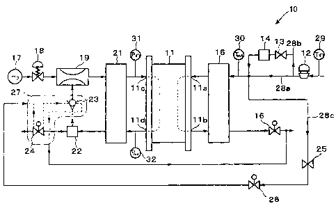
Fig. 1 is a diagram showing a structure of a start
control device of a fuel cell according to one embodiment of
the present invention.
Fig. 2 is a cross-sectional view of a warm-up box
shown in Fig. 1.
CA 02380213 2002-04-04
6
Fig. 3 is a flowchart showing an operation of the start control device of a
fuel cell
shown in Fig. 1.
Fig. 4 is a flowchart showing an operation at step S 10 including a control
operation. of valves at the time of starting the fuel cell at a low
temperature region and a
control process for determining completion of defrosting.
DETAILED DESCRIPTION OF THE INVENTION
A start control device of a fuel cell according to one embodiment of the
present
invention is described below with reference to the attached drawings.
Fig. 1 is a diagram showing a structure of a start control device of a fuel
cell
according to one embodiment of the present invention, and Fig. 2 is a cross-
sectional view
of a warm-up box shown in Fig. 1.
The control device 10 according to one embodiment of the present invention is
installed in, for example, an electric vehicle, and the control device 10
comprises a fuel
cell 11, an oxidant supply portion 12, a bypass valve 13, a heat exchanger 14,
an oxidizer
humidifier 15, a back pressure portion 16, a fuel supply portion 17, a first
pressure flow
control valve 18, an ejector 19, a fuel humidification portion 21, a liquid
separating
portion 22, a check valve 23, a discharge valve 24, an orifice 25, and a warm
up flow
dividing valve 26.
The fuel cell 11 is constituted by a fuel cell stack composed by stacking a
plurality of cells each formed by sandwiching both sides of a solid polymer
electrolyte
membrane, corresponding to, for exarnple, a solid polymer ion exchange
membrane, by an
anode and a cathode, and the fuel cell I 1 is provided with a fuel electrode,
to which a fuel
gas such as hydrogen is supplied, and an air electrode, to which air
containing oxygen as
an oxidant gas is supplied.
CA 02380213 2002-04-04
7
The air electrode of the fuel cell 11 is provided with an air supply port 11 a
for
supplying air from the oxidant supply portion 12 and an air discharge port 11
b for
discharging air and the like in the air electrode to the outside. In contrast,
the fuel
electrode is provided with a fuel supply port 11 c for supplying hydrogen and
a fuel
discharge port 1 l d for discharging hydrogen and the like in the fuel
electrode.
The air supply portion 12, constituted by, for example, an air compressor, is
controlled by input signals in response to loads of the fuel cell 11 and the
accelerator pedal
(not shown) and supplies compressed air to the air electrode of the fuel cell
11 or to the
warm-up box 27, described below.
Furthermore, a bypass passage 28b, detouring around an oxidant gas passage
28a,
is provided at an oxidant gas passage 28a, connecting the air supply portion
12 with the
oxidant humidifier 15.
The aforementioned bypass passage 28b is provided with a heat exchanger 14, to
which a high temperature gas, adiabatically compressed at the air supply
portion 12, is
supplied through a bypass valve 13, and the heat exchanger 14 supplies the
high
temperature air after being cooled to a predetermined temperature to the air
supply port
11 a of the fuel cell 11.
A flow dividing passage 28c for supplying high temperature air, after being
adiabatically compressed at the air supply portion 12 to the warm-up box 27,
is provided
at the oxidant gas passage 28a. This flow dividing passage 28c is provided
with, for
example, a fixed type orifice 25 anda warm-up air flow dividing valve 26, and
an opening
and closing movement of the warm-up air flow dividing valve 26 controls supply
and stop
of supplying high temperature air to the warm-up box 27.
Note that the oxidant humidifier 15 utilizes the discharging oxidant gas
discharged from the air discharge port 1 l b of the fuel cell 11 as a
humidifying gas for the
CA 02380213 2002-04-04
8
oxidant gas (that is, air) supplied from the air supply portion 12 to the air
supply portion
11 a of the fuel cell 11. That is, for example, when the oxidant gas is made
to contact
the discharged oxidant gas through a water permeable membrane such as a hollow
fiber
membrane, the water content (particularly, vapor) contained in the discharged
oxidant gas
is supplied to the oxidant gas as vapor through pores of the hollow fiber
membrane.
Hydrogen as the fuel gas is supplied to the fuel electrode of the fuel cell 11
through a fuel supply portion 17, the first pressure flow control valve 18,
the ejector 19,
and a second pressure flow control valve 20.
In addition, the fuel gas, which is discharged from. the fuel discharge port
11 d of
the fuel cell as non-reacted fuel gas, is introduced sequentially to the
liquid separating
portion 22, the check valve 23, and to the ejector 19, and the fuel gas
supplied from the
first pressure flow control valve 18 and the discharged fuel discharged from
the fuel cell
11 is mixed and the mixture is again supplied to the fuel cell 11.
Note that an inlet pressure sensor 31 for detecting a pressure of the fuel gas
to be
supplied to the fuel cell 11 is provided in proximity to the fizel supply port
11a, and an
outlet pressure sensor 32 is provided for detecting the pressure of the fuel
gas discharged
from the fuel cell in proximity to the fuel discharge port 11 d.
The ejector 19 absorbs the discharged fuel gas discharged from the fuel cell
11 as
the subsidiary flow by a negative pressure generated by high speed fuel gas
flowing in the
ejector 19, and thereby the fuel gas discharged from the fuel cell l1 is
distributed by
supplying the discharged fuel gas to the fuel cell 11 after mixing with the
fuel gas supplied
through the first pressure flow control valve and forms a circulating passage.
The fuel gas humidifier 21 utilizes the discharge gas discharged from the fuel
discharge port l l d of the fuel cell 11 as the humidifying gas for the fuel
gas (that is,
hydrogen), which issupplied to the fuel supply port 11c of the fuel cell 11
from the fuel
CA 02380213 2006-11-02
79225-10
9
supply portion 17. That is, when the fuel gas is in contact with the
discharged fuel gas
through a water permeable membrane such as the hollow fiber membrane, the
water
content (particularly, water vapor) in the discharged fuel gas is supplied to
the fuel gas
after permeating through the hollow fiber membrane.
The liquid separating portion 22 performs a liquid separation for the
discharged
fuel gas after being discharged from the fuel discharge port l i d of the fuel
cell 11 and
subsequently passing through the fuel gas humidifier 21, and after the liquid
water content
is removed, the discharged fuel gas is stored.
Here, as shown in Fig. 2, the control valves provided at the discharge gas
passage
such as the check valve 23 and the discharge valve 24 are contained in the
warm-up box
27, and introduction of hot air into the warm-up box 27 through the warm-up
dividing
valve 26 makes it possible to blow hot air directly for defrosting respective
frozen
solenoids 23a and 24a of check valve 23 and the discharge valve 24.
The control device 10 for starting the fuel cell according to the present
embodiment is constructed as described above.
Hereinafter, operations of the above-described control device 10 for starting
the
fuel cell are described with reference to attached drawings.
Fig. 3 is a flowchart showing an operation of the start control device of a
fuel cell
shown in Fig. 1. Fig. 4 is a flowchart showing an operation at step S 10
including a
control operation of valves at the time of starting the fuel cell at a low
temperature region
and a control process for determining completion of defrosting. In addition,
output
signals from respective sensors are input into the control device (not shown)
and the
control device controls the operations of respective control valves.
In step SOl shown in Fig. 3, the air supply portion 12 starts to supply air.
In step
S02, the fuel gas supply portion 17 starts to supply the fuel gas.
CA 02380213 2002-04-04
Subsequently, in step S03, the control operation of valves at the start time
begins.
Subsequently, in step S04, it is determined whether the external temperature
Tin
detected by, for example, an intake air temperature sensor 29 is below a low
external
temperature, which is below a predetermined temperature #T.
When the determination in step S04 is "YES", it is determined that the control
valves (such as the check valve 23 or the discharge valve 24) are frozen, and
the flow
proceeds to step S09. When the determination in step S04 is "NO", it is
determined that
the control valves can move normally, and the step proceeds to step S05.
In step S05, the regular starting operations begin, such as by outputting
commands to close the check valve 23 and to open the discharge valve 24.
In step S06, the warm up dividing valve 26 is closed, and in step S07, it is
determined whether the fuel cell 11 is ready to start generating power. Here,
it is
determined that the fuel cell is ready to start generating power when an
opening voltage
(OCV) of the fuel cell 11 reaches a predetermined voltage.
When the determination in step S07 is "NO", the flow returns to step S07. In
contrast, when the determination is "YES", the flow proceeds to step S08.
In step S08, the flow for starting the fuel cell is completed by starting
generation
of power and by supplying electric power generated by the fuel cell to
external loads.
In contrast, in step S09, the dividing valve 26 for vvarming up is opened and
by
supplying an adiabatically compressed oxidant gas into the warm-up box 27,
control
valves (such as the check valve 23 and the discharge valve 24) are heated by
the heat
exchange process of the control valves with the oxidant gas.
In step S 10, it is determined whether a valve control operation at a time of
starting at low temperature range, which will be described below, and a
defrosting
operation, are completed.
CA 02380213 2006-11-02
79225-10
11
Subsequently, in step S11, it is determined whether the defrosting operation
is
completed.
When the determination in step S 11 is "NO", the flow returns to step S 10,
and
when the determination is "YES", the flow proceeds to step S06.
Hereinafter, the valve control operation when the vehicle is started at a low
temperature and the defrosting operation in step S 10 will be explained.
In step S21 shown in Fig. 4, it is determined whether a defrosting operation
of,
for example, the frozen discharge valve (purge valve) 24 has been completed.
When the determination is "NO", the flow proceeds to step S27, described
below,
and when the determination is "YES", the flow proceeds to step S22. (The first
determination after starting the fuel cell is "NO", and the flow proceeds to
step S27).
In step S22, a command to close the check valve 23 is output and in subsequent
step S23, a command to open the discharge valve (purge valve) 24 is output.
In step S24, it is determined whether the fuel gas pressure Pin, which is
detected
by the inlet pressure sensor 31 and is to be supplied to the fuel cell 11,
exceeds a
predetermined memory value #Pm.
When the determination is "YES", the flow proceeds to step S25, wherein it is
determined that a series of defrosting operations has been finished (that is,
it is determined
that both control valves, i.e., the check valve 23 and the discharge valve 24,
are defrosted
and the defrosting operation in step S 11 is completed, and the flow is
completed.
CA 02380213 2006-11-02
79225-10
lla
In contrast, when the determination is "NO", the
flow proceeds to step S26, wherein it is determined that a
series of defrosting operations is not completed, and the
flow is completed.
In contrast, in step S27, a command to defrost the
check valve 23 is output and in subsequent step S28, a
command to open the discharge valve (purge valve) 24 is
output.
In step S29, it is determined whether the
discharged gas pressure Pout, which is detected by the
outlet pressure sensor 32 and is discharged from the fuel
cell 11, is below a predetermined pressure #P.
CA 02380213 2002-04-04
12
When the determination is "YES", the flow proceeds to step S30, wherein it is
determined that the discharge valve (purge valve) 24 has been defrosted.
Subsequently, in step S3 1, a fuel gas pressure Pin, which is detected by the
inlet
pressure sensor 31 and is to be supplied to the fuel cell 11 is stored in the
memory as a
memory value #Pm, and the routine process flow is completed.
In contrast, when the determination in step S29 is "NO", the flow proceeds to
step
S32, wherein it is determined that the defrosting operation of a discharge
valve (purge
valve) is not completed and the routine process flow is completed.
That is, when the fuel cell 11 is started at a low temperature wherein
respective
solenoids of the check valve 23 and the discharge valve 24 are frozen, high
temperature air
adiabatically compressed at the air supply portion 12 is diverged and supplied
to the
warm-up box 27 which receives the check valve 23 and the discharge valve 24.
Here; when the check valve is in a frozen state, a nonreturn function, that
is, a
function to limit the fuel stream flowing from the ejector to the liquid
separating portion is
damaged, and the check valve 23 is maintained in the closed position.
When the discharge valve 24 is ina frozen state, the discharge function, for
example, is lost, and the fuel cell is in a locked state because the discharge
valve 24 is
closed.
Accordingly, it is determined whether the discharge valve 24 is defrosted by
examining whether the discharge valve 24 can be opened while maintaining the
check
valve 23 in the open state. When the discharge valve 24 is opened, the
discharge fuel gas
pressure Pout in the vicinity of the discharge port of the fuel cell 11
decreases towards the
outlet of the discharge valve 24.
When the defrosting operation of the discharge valve 24 is completed, it is
determined whether the check valve 231s defrosted by examining whether the
check valve
CA 02380213 2002-04-04
13
can be opened actually. When the check valve 23 is opened, the fuel gas
pressure Pin in
the vicinity of the fuel supply port 11 c of the fuel cell l 1 increases.
As described above, the start control device 10 of the fuel cell according to
the
present embodiment utilizes hot air obtained by dividing adiabatically
compressed air
obtained by the air supply portion 12, which corresponds to an compressor for
defrosting
respective solenoids of the check valve 23 and the discharge valve 24, which
is likely to
be in the frozen state due to residual water, it is possible to efficiently
conduct defrosting
operations of those valves by effective utilization of thermal energy due to
compression
heating by use of a compressor without necessitating provision of a particular
device for
heating control valves.
Furthermore, since the check valve 23 and the discharge valve 24 are
concentrically disposed in the warm-up box, these valves can be defrosted
merely by
introducing hot air into the warm-up box, which results in improving
defrosting efficiency.
In addition, since division of hot air into the warm-up box is controlled by
an
opening or closing operation of the warm up air flow dividing valve 26, and
since the air
flow into the warm-up box can be stopped merely by closing the warm-up air
flow .
dividing valve 26, it is possible to prevent unnecessary consumption of air,
which contains
oxidant gas for the fuel cell 11; and to restrict power consiunption for
driving,the
compressor, which result in accomplish the defrosting operation efficiently.
Note that the warm-up operation is not limited to the defrosting operation
described in this embodiment, in which hot air, obtained by adiabatic
compression in the
air supply portion 12, is blown on control valves such as the check valve 23
and the
discharge valve 24, provided in the fuel gas passage, and a variant thereof
may be
conducted, in which aforementioned hot air is blown on the back pressure valve
16.
In addition, it may be possible to conduct the warm-up operation by providing
a
CA 02380213 2002-04-04
14
common warm-up box, in which a plurality of control valves located in the
oxidant gas
discharge passage are concentrically disposed, and by supplying hot air into
the warm-up
box.
As described above, the first aspect of the present invention provide a start
control device for a fuel cell system, capable of quickly defrosting solenoids
of the check
valve and the discharge valve of the fuel cell and capable of saving time for
warming up
the entire fuel cell system, when these control valves are frozen by residual
water because
the fuel cell has been exposed to a low subzero temperature.
Accordingly, it is possible to conduct the warm-up operation by effectively
utilizing the thermal energy obtained by adiabatic compression of the oxidant
gas, without
necessitating provision of particular devices for heating control valves.
In the start control device for the fuel cell according to the second aspect
of the
present invention, the oxidant gas heated by adiabatic compression can heat
the control
valves and the fuel cell so that it is possible to reduce the time for warming
up the entire
fuel cell system.
In the start control device of a fuel cell according to the third and fourth
aspects,
it is possible to prevent supplying unnecessary oxidant gas and to carry out
defrosting
operation efficiently.
In the start control device for the fuel cell according to the fiifth aspect
of the
present invention, it is possible to determine whether the control valves are
defrosted by
detecting the gas pressure of the reaction gas in response to commands to open
or close
control valves.
In the control device for starting the fuel cell according to the sixth aspect
of the
present invention, the fuel cell is capable of executing normal power
generation without
being subjected to reduction of the power generation efficiency because the
power
CA 02380213 2002-04-04
generation the fuel cell starts after the smooth operations of control valves
thereof are
confirmed.
In the control device for starting the fuel cell according to the seventh
aspectof
the present invention, it is possible to prevent useless diffusion of the
oxidant gas which
would not contribute to heating operation of the control valves and thereby
improving the
heating efficiency.