Language selection

Search

Patent 2380533 Summary

Third-party information liability

Some of the information on this Web page has been provided by external sources. The Government of Canada is not responsible for the accuracy, reliability or currency of the information supplied by external sources. Users wishing to rely upon this information should consult directly with the source of the information. Content provided by external sources is not subject to official languages, privacy and accessibility requirements.

Claims and Abstract availability

Any discrepancies in the text and image of the Claims and Abstract are due to differing posting times. Text of the Claims and Abstract are posted:

  • At the time the application is open to public inspection;
  • At the time of issue of the patent (grant).
(12) Patent Application: (11) CA 2380533
(54) English Title: APPARATUS FOR HEATING FLOWING MATERIAL CONTAINING SOLIDS
(54) French Title: APPAREIL DE CHAUFFAGE DE MATIERE FLUIDE CONTENANT DES SOLIDES
Status: Deemed Abandoned and Beyond the Period of Reinstatement - Pending Response to Notice of Disregarded Communication
Bibliographic Data
(51) International Patent Classification (IPC):
  • C22B 9/00 (2006.01)
  • C22B 3/02 (2006.01)
  • C22B 11/00 (2006.01)
  • F27B 15/00 (2006.01)
(72) Inventors :
  • NAAPPA, TAPIO (Finland)
(73) Owners :
  • OUTOKUMPU OYJ
(71) Applicants :
  • OUTOKUMPU OYJ (Finland)
(74) Agent: NORTON ROSE FULBRIGHT CANADA LLP/S.E.N.C.R.L., S.R.L.
(74) Associate agent:
(45) Issued:
(86) PCT Filing Date: 2000-07-21
(87) Open to Public Inspection: 2001-02-08
Examination requested: 2005-07-07
Availability of licence: N/A
Dedicated to the Public: N/A
(25) Language of filing: English

Patent Cooperation Treaty (PCT): Yes
(86) PCT Filing Number: PCT/FI2000/000656
(87) International Publication Number: WO 2001009398
(85) National Entry: 2002-01-25

(30) Application Priority Data:
Application No. Country/Territory Date
19991657 (Finland) 1999-07-29

Abstracts

English Abstract


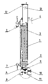
The invention relates to an apparatus for the heating of flowing material
containing finely divided solids, such as concentrate slurry containing
precious metals and/or precious minerals, up to a desired temperature range,
for instance the temperature range applied in a treatment process of said
material, said apparatus comprising means for feeding and removing the medium
used for heating as well as means for feeding and removing the material to be
heated in and out of the apparatus. According to the invention, both the
flowing space of the material to be heated and the flow channels (3) of the
heating medium are installed in an essentially vertical position, so that the
material to be heated can be fed to the bottom part of the flowing space, and
the heating medium can be fed to the top part of the flow channels (3), and
that in the feed chamber (5) of the material to be heated, there are installed
means (9) for cleaning the feed chamber (5).


French Abstract

La présente invention concerne un appareil permettant de chauffer une matière fluide contenant des solides finement broyés, tels une pulpe de concentré contenant des métaux précieux et/ou des minéraux précieux jusqu'à une plage de température désirée, par exemple la plage de température utilisée dans le traitement de ladite matière, ledit appareil comprenant des moyens d'alimentation et de retrait du milieu utilisé pour le chauffage ainsi que des moyens d'alimentation et de retrait de la matière à chauffer dans l'appareil et hors de l'appareil. Selon l'invention, l'espace d'écoulement de la matière à chauffer ainsi que les canaux d'écoulement (3) du milieu de chauffage sont installés dans une position sensiblement verticale, de sorte que la matière à chauffer peut être alimentée à la partie basse de l'espace d'écoulement, et le milieu de chauffage peut être alimenté à la partie haute des canaux d'écoulement (3) et que dans l'enceinte d'alimentation (5) de la matière à chauffer, sont pourvus des moyens (9) permettant de nettoyer la chambre d'alimentation (5).

Claims

Note: Claims are shown in the official language in which they were submitted.


7
CLAIMS
1. An apparatus for the heating of flowing material containing finely divided
solids, such as concentrate slurry containing precious metals and/or precious
minerals, up to a desired temperature range applied for instance in a
treatment
process of said material, said apparatus comprising means for feeding and
removing the medium used for heating as well as means for feeding and
removing the material to be heated in and out of the apparatus, characterized
in that both the flow space of the material to be heated as well as the flow
channels (3) of the medium used for heating are installed in an essentially
verti-
cal position, so that the material to be heated can be fed to the bottom part
of
the flow space, and the heating medium can be fed to the top part of the flow
channels (3), and that in the feed chamber (5) of the material to be heated,
there are installed means (9) for cleaning the feed chamber (5).
2. An apparatus according to claim 1, characterized in that on the bottom of
the feed chamber (5) of the material to be heated, there is installed, in
order to
provide for the cleaning of the feed chamber, an adjusting element (9), which
is
made to be operated by the pressure of a cleaning agent fed via said adjusting
element (9).
3. An apparatus according to claim 1 or 2, characterized in that the adjusting
element (9) installed on the bottom of the feed chamber (5) of the material to
be
heated is a valve.
4. An apparatus according to claim 1, 2 or 3, characterized in that the
cleaning
agent conducted to the feed chamber (5) of the material to be heated is gas.
5. An apparatus according to claim 1, 2 or 3, characterized in that the
cleaning
agent conducted to the feed chamber (5) of the material to be heated is
liquid.

8
6. An apparatus according to any of the preceding claims, characterized in
that
the flow channels (3) of the heating medium are interconnected and attached to
the heat exchanger (1) by a flange joint.
7. An apparatus according to any of the preceding claims, characterized in
that
both the adjusting element (9) and the flow channels (3) of the heating medium
are, at least for the section that is in contact with the material to be
heated,
coated with a wear-resistant material.
8. An apparatus according to any of the preceding claims, characterized in
that
the transversal flowing area of the flowing space of the material to be heated
and the transversal flowing area of the flow channels (3) of the heating
medium
are mutually matched, so that the material to be heated is in suspension essen-
tially throughout the heating process.

Description

Note: Descriptions are shown in the official language in which they were submitted.


CA 02380533 2002-O1-25
WO 01/09398 PCT/FI00/00656
1
APPARATUS FOR HEATING FLOWING MATERIAL CONTAINING SOLIDS
The present invention relates to a device for heating flowing material
containing
finely divided solids, such as concentrate, slurry containing precious metals
and/or precious minerals, up to a desired temperature range, for instance to a
temperature range used in the treatment process of said material.
The heating of a concentrate slurry containing finely divided solids, such as
precious metals and/or precious minerals, up to the temperature range used in
the treatment process is usually carried out in a heat exchanger with a hot,
liquid medium, such as water or vapor. However, the concentrate slurry is an
extremely abrasive and easily settling material which is difficult to treat in
heat
exchangers. The reason for said difficulty is that the ducts provided in heat
exchangers for the flowing of the heated material often are essentially very
narrow, and the duct walls are thin. Consequently, in the treatment of concen-
trate slurries, the heat exchanger ducts wear rapidly off or are blocked, if
the
flow is too weak in order to carry the solids along with the liquid phase
present
in the slurry.
The object of the present invention is to eliminate some of the drawbacks of
the
prior art and to achieve and improved apparatus that is more secure in opera-
tion for heating flowing material containing finely divided solids, such as
concentrate slurry containing precious metals and/or precious minerals, up to
the temperature range applied in the treatment process of said material, when
a
heat exchanger is employed for heating. The essential novel features of the
invention are apparent from the appended claims.
According to the invention, the heating of flowing material containing finely
divided solids, such as concentrate slurry containing precious metals and/or
precious minerals, up to a desired temperature range is carried out in a heat
exchanger that is set in an essentially vertical position. The medium, such as

CA 02380533 2002-O1-25
WO 01/09398 PCT/FI00/00656
2
water or vapor, used in the heat exchanger for heating the material is
conducted to flow channels that are advantageously installed, apart from the
adjusting elements connected to the medium inlet and outlet conduits, in an
essentially vertical position, so that the medium used for heating proceeds in
the channels from top to bottom. Moreover, the flow channels of the medium
used for heating are installed, with respect to each other, so that they are
located essentially at regular intervals. In addition, the flow channels are
advan-
tageously provided, at least as regards the surface that gets in contact with
the
heated material, with a particular wearing element, which further reduces the
wearing effects of the material to be heated. In shape, the flow channels are
advantageously tubular, but they can also have some other shape, for instance
rectangular or square in cross-section.
In the apparatus according to the invention, the flowing material containing
finely divided solids, such as concentrate slurry containing precious metals
and/or precious minerals, is fed from bottom to top, essentially in a vertical
position in between flow channels contained by the medium used for heating,
and consequently in the opposite direction with respect to the flowing
direction
of the heating medium. With respect to each other, the flow channels of the
heating medium are installed so that the material to be heated is maintained
in
suspension, which prevents the classification of said material. Thus the trans-
versal flowing area of the flowing space of the material to be heated and the
transversal flowing area of the flow channels of the heating medium are
mutually matched in order to keep the material to be heated in suspension
essentially throughout the heating process. The flowing of the material to be
heated is advantageously turbulent, but when the flowing takes place essen-
tially vertically upwards, the settling of the solids contained in the
material to be
heated does not occur as easily as in a corresponding, essentially horizontal
flow.

CA 02380533 2002-O1-25
WO 01/09398 PCT/FI00/00656
3
The flow channels of the heating medium used in the apparatus according to
the invention are advantageously interconnected to form a flow channel
system, so that said flow channel system can be connected to the housing
element of the apparatus according to the invention, advantageously by a
flange joint, for example. Thus the connecting of the flow channel system to
the
apparatus housing also constitutes part of the support structure of said
appara-
tus. When the flow channel system is attached to the housing element by a
flange joint, it can easily be detached from the housing when necessary, for
instance for possible maintenance of the flow channel system.
In the flow channels of the apparatus according to the invention, there is
advan-
tageously maintained a pressure that is higher than at least the hydrostatic
pressure of the material to be heated. This prevents, in the event of possible
damages, the access of the material to be heated to the flow channels consist-
ing of the heating medium. When desired, also that part of the apparatus
according to the invention that contains the material to be heated can be
pressurized. In that case, when defining the pressure to be maintained in the
flow channels, also the pressure in the part that contains the material to be
heated must be taken into account.
In order to feed the material to be heated into the apparatus according to the
invention, in the bottom part of the apparatus, advantageously underneath the
heating medium flow channel system, there is provided a feed chamber, and
the walls of said feed chamber are, at least as regards the sections that are
in
contact with the material to be heated, essentially equally thick as the walls
of
the flow channels, and advantageously coated with some wear-proof material.
On the bottom of the feed chamber of the material to be heated, there is advan-
tageously attached an adjusting element, such as a valve, in order to adjust
the
medium flow coming from the chamber formed underneath said adjusting
element. When necessary, in the chamber formed underneath said adjusting

CA 02380533 2002-O1-25
WO 01/09398 PCT/FI00/00656
4
element, there can be fed gas, such as air, and/or liquid, such as water, in
order to advantageously improve the functionality of the apparatus.
Advantageously the adjusting element attached on the bottom of the feed
chamber of the material to be heated is a mushroom valve with replaceable
wearing parts and sealing. The valve is arranged to operate by the pressure of
the gas and/or liquid to be fed in the chamber formed underneath the valve.
The mushroom element of the valve rises upwardly by the pressure of the gas
or liquid fed in the chamber, in which case the medium flowing from the valve,
advantageously a gaseous medium, lifts the possible coarser solid particles of
the material to be heated advantageously back to the material flow. On the
other hand, the liquid medium to be fed in the chamber is mainly used for
preventing the blocking of the apparatus according to the invention, if the
veloc-
ity of the material to be heated is too low, or if the material to be heated
contains particles so coarse that they are not carried along with the flow.
Normally the medium that is fed via the chamber located underneath the adjust
ing element is used in the apparatus according to the invention preferably so
that the employed medium is mainly a gaseous medium, which is replaced by a
liquid medium or into which there is added liquid medium, when the surfaces of
the adjusting element should be washed.
The invention is explained in more detail with reference to the appended
drawing, which illustrates a preferred embodiment of the invention, seen from
the side in a partial cross-section.
According to the drawing, the heating of a flowing concentrate slurry
containing
finely divided solids, such as precious metals and/or precious minerals, up to
a
desired temperature range applied in the treatment process of said material,
is
carried out in an essentially vertically installed heat exchanger 1. The water
or
vapor needed in the heating is fed to the top part of the heat exchanger 1,
via a
feed duct 2, to essentially vertically installed flow channels 3, where the
flowing

CA 02380533 2002-O1-25
WO 01/09398 PCT/FI00/00656
direction of the heating medium proceeds from top to bottom. As for the
concentrate slurry to be heated, it is fed via its inlet conduit 4 to a feed
chamber
5 provided in the bottom part of the heat exchanger 1. From the feed chamber
5, the concentrate slurry to be heated is further conducted from the bottom
5 upwards in between the flow channels 3. When flowing between the flow
channels 3, the concentrate slurry to be heated is maintained in suspension in
order to prevent classification. The heated concentrate slurry is further
removed
from the top part of the heat exchanger 1 via an outlet conduit 6. The water
or
vapor used for heating is discharged via an outlet conduit 7 provided in the
bottom part of the heat exchanger 1.
Moreover, underneath the concentrate slurry feed chamber 5, there is formed a
chamber 8 whereto there is fed, via a feed conduit 10, air and/or water used
in
the cleaning of the feed chamber 5. In order to conduct the air and/or water
that
was fed into the chamber 8 further to the concentrate slurry feed chamber 5,
on
the bottom of the concentrate slurry feed chamber 5 there is installed a
mushroom valve 9 that is operated by the pressure defined by the air and/or
water fed in the chamber 8. By means of the air and/or water fed in said
chamber 8, the bottom of the concentrate slurry feed chamber 5 is cleaned of
possible concentrate particles that came along with the concentrate slurry and
were left on the bottom, which particles are not - owing to their coarseness,
for
example - carried along with the upwardly, from bottom to top, flowing
vertical
concentrate slurry flow. The material that should be removed from the chamber
8 by cleaning, as well as the medium used in the cleaning process, are
discharged from the heat exchanger 1 via a discharge conduit 11 provided on
the bottom of the heat exchanger 1.
Further, in order to provide for the maintenance of the apparatus 1 according
to
the invention, in the top part of the apparatus, there is installed a door 12.
Moreover, in the drawing there is shown, marked with number 13, an overflow

CA 02380533 2002-O1-25
WO 01/09398 PCT/FI00/00656
conduit wherethrough the heated concentrate slurry can be discharged in
possible malfunction situations.

Representative Drawing
A single figure which represents the drawing illustrating the invention.
Administrative Status

2024-08-01:As part of the Next Generation Patents (NGP) transition, the Canadian Patents Database (CPD) now contains a more detailed Event History, which replicates the Event Log of our new back-office solution.

Please note that "Inactive:" events refers to events no longer in use in our new back-office solution.

For a clearer understanding of the status of the application/patent presented on this page, the site Disclaimer , as well as the definitions for Patent , Event History , Maintenance Fee  and Payment History  should be consulted.

Event History

Description Date
Time Limit for Reversal Expired 2008-07-21
Application Not Reinstated by Deadline 2008-07-21
Deemed Abandoned - Failure to Respond to Maintenance Fee Notice 2007-07-23
Inactive: IPC from MCD 2006-03-12
Letter Sent 2005-08-12
Amendment Received - Voluntary Amendment 2005-07-07
Request for Examination Received 2005-07-07
All Requirements for Examination Determined Compliant 2005-07-07
Request for Examination Requirements Determined Compliant 2005-07-07
Inactive: Correspondence - Transfer 2003-03-04
Letter Sent 2003-01-22
Inactive: Single transfer 2002-11-21
Inactive: Cover page published 2002-07-24
Inactive: Courtesy letter - Evidence 2002-07-23
Inactive: Notice - National entry - No RFE 2002-07-18
Application Received - PCT 2002-05-13
National Entry Requirements Determined Compliant 2002-01-25
Application Published (Open to Public Inspection) 2001-02-08

Abandonment History

Abandonment Date Reason Reinstatement Date
2007-07-23

Maintenance Fee

The last payment was received on 2006-06-28

Note : If the full payment has not been received on or before the date indicated, a further fee may be required which may be one of the following

  • the reinstatement fee;
  • the late payment fee; or
  • additional fee to reverse deemed expiry.

Please refer to the CIPO Patent Fees web page to see all current fee amounts.

Fee History

Fee Type Anniversary Year Due Date Paid Date
MF (application, 2nd anniv.) - standard 02 2002-07-22 2002-01-25
Basic national fee - standard 2002-01-25
Registration of a document 2002-11-21
MF (application, 3rd anniv.) - standard 03 2003-07-21 2003-06-25
MF (application, 4th anniv.) - standard 04 2004-07-21 2004-06-15
MF (application, 5th anniv.) - standard 05 2005-07-21 2005-06-20
Request for examination - standard 2005-07-07
MF (application, 6th anniv.) - standard 06 2006-07-21 2006-06-28
Owners on Record

Note: Records showing the ownership history in alphabetical order.

Current Owners on Record
OUTOKUMPU OYJ
Past Owners on Record
TAPIO NAAPPA
Past Owners that do not appear in the "Owners on Record" listing will appear in other documentation within the application.
Documents

To view selected files, please enter reCAPTCHA code :


To view images, click a link in the Document Description column. To download the documents, select one or more checkboxes in the first column and then click the "Download Selected in PDF format (Zip Archive)" or the "Download Selected as Single PDF" button.

List of published and non-published patent-specific documents on the CPD .

If you have any difficulty accessing content, you can call the Client Service Centre at 1-866-997-1936 or send them an e-mail at CIPO Client Service Centre.


Document
Description 
Date
(yyyy-mm-dd) 
Number of pages   Size of Image (KB) 
Representative drawing 2002-07-23 1 8
Cover Page 2002-07-24 1 44
Claims 2002-01-25 2 63
Abstract 2002-01-25 2 67
Description 2002-01-25 6 250
Drawings 2002-01-25 1 20
Notice of National Entry 2002-07-18 1 208
Request for evidence or missing transfer 2003-01-28 1 102
Courtesy - Certificate of registration (related document(s)) 2003-01-22 1 107
Reminder - Request for Examination 2005-03-22 1 117
Acknowledgement of Request for Examination 2005-08-12 1 177
Courtesy - Abandonment Letter (Maintenance Fee) 2007-09-17 1 177
PCT 2002-01-25 7 268
Correspondence 2002-07-18 1 24