Language selection

Search

Patent 2380809 Summary

Third-party information liability

Some of the information on this Web page has been provided by external sources. The Government of Canada is not responsible for the accuracy, reliability or currency of the information supplied by external sources. Users wishing to rely upon this information should consult directly with the source of the information. Content provided by external sources is not subject to official languages, privacy and accessibility requirements.

Claims and Abstract availability

Any discrepancies in the text and image of the Claims and Abstract are due to differing posting times. Text of the Claims and Abstract are posted:

  • At the time the application is open to public inspection;
  • At the time of issue of the patent (grant).
(12) Patent: (11) CA 2380809
(54) English Title: DEVICE FOR CONVEYING FLAT OBJECTS WITH A SYNCHRONIZATION SYSTEM
(54) French Title: APPAREIL PERMETTANT LE TRANSPORT D'OBJETS PLATS AVEC UN SYSTEME DE SYNCHRONISATION
Status: Expired and beyond the Period of Reversal
Bibliographic Data
(51) International Patent Classification (IPC):
  • B65H 29/12 (2006.01)
  • B07C 01/04 (2006.01)
  • B65H 05/06 (2006.01)
(72) Inventors :
  • CHAUME, FRANCOIS (France)
  • BUFFAT, LAURENT (France)
  • DIEBOLD, CLAUDE (France)
(73) Owners :
  • SOLYSTIC
(71) Applicants :
  • SOLYSTIC (France)
(74) Agent: BORDEN LADNER GERVAIS LLP
(74) Associate agent:
(45) Issued: 2007-04-03
(86) PCT Filing Date: 2000-08-01
(87) Open to Public Inspection: 2001-02-15
Examination requested: 2004-03-12
Availability of licence: N/A
Dedicated to the Public: N/A
(25) Language of filing: English

Patent Cooperation Treaty (PCT): Yes
(86) PCT Filing Number: PCT/EP2000/007448
(87) International Publication Number: EP2000007448
(85) National Entry: 2002-02-04

(30) Application Priority Data:
Application No. Country/Territory Date
99/10308 (France) 1999-08-09

Abstracts

English Abstract


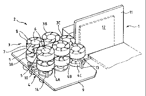
The device for conveying flat objects in series and edge-on, in which the said
flat objects (12) are moved in a conveying
direction (D), while at the same time being separated each from the next by a
spacing which is normally constant, comprises
a synchronization system (2) capable of compensating for any variations in
spacing between two consecutive objects, this system
comprising two parallel rows (3, 4) of driven wheels (3A-4C) made of
elastically deformable elastomer and between which each
object is gripped and moved in said conveying direction. Each wheel has a
rotation spindle (6), the position of which is fixed, and
the wheels are rotated by a motorization system which is controlled to
accelerate and/or retard the movement of each object between
the two rows of wheels on the basis of a detection as to whether the front
edge of the object has been early or late in passing a
determined position upstream of the two rows of wheels, compared with a time
reference which indicates the spacing between objects.
Application to a postal sorting machine operating in synchronous mode.


French Abstract

La présente invention concerne un appareil permettant le transport d'objets plats, en série et sur la tranche, dans lequel lesdits objets plats (12) sont déplacés dans une direction de transport (D) et sont simultanément séparés les uns des autres par un intervalle qui est normalement constant. Cet appareil comprend un système de synchronisation (2) qui est capable de compenser toute variation d'intervalle entre deux objets consécutifs et qui comprend deux rangées parallèles (3, 4) de roues entraînées (3A-4C) constituées d'un élastomère pouvant se déformer de façon élastique et entre lesquelles chaque objet est pris et déplacé dans ladite direction de transport. Chaque roue présente un axe de rotation (6) dont la position est fixe. Les roues sont mises en rotation par un système motorisé qui est commandé afin d'accélérer et/ou de retarder le mouvement de chaque objet entre les deux rangées de roues, en fonction d'une détection mettant en évidence si la partie antérieure de l'objet est passée en avance ou en retard dans une position déterminée, en amont des deux rangées de roues, par comparaison avec une référence temporelle qui indique l'intervalle entre les objets. Cette invention concerne également l'application d'un tel appareil à une machine de tri postal fonctionnant en mode synchrone.

Claims

Note: Claims are shown in the official language in which they were submitted.


6
CLAIMS:
1. A device for conveying flat objects in series and edge-on, in which said
flat
objects are moved in a conveying direction while at the same time being
separated each from the next by a spacing which is normally constant, which
device further comprises a synchronization system capable of compensating for
any variations in spacing between two consecutive objects, wherein this system
further comprises two parallel rows of driven wheels made of elastically
deformable elastomer and between which each object is gripped and moved in
said conveying direction, each wheel having a rotation spindle, the position
of
which is fixed, each fixed-position rotation spindle comprising two twin
wheels, the
wheels of the two rows of wheels located upstream in the direction of
conveying
extending over a shorter height than the wheels located downstream, and the
wheels being rotated by a motorization system which is controlled to
accelerate or
retard the movement of each object between the two rows of wheels on the basis
of a detection as to whether the front edge of the object has been early or
late in
passing a determined position upstream of the two rows of wheels, compared
with
a time reference which indicates the spacing between objects.
2. The device as claimed in claim 1, comprising a first sensor disposed close
to the upstream wheels of the two rows of wheels in the conveying direction
and
arranged to detect the passage of the front edge of each flat object, and a
second
sensor disposed close to the downstream wheels of the two rows of wheels in
the
conveying direction and arranged to detect the passage of the rear edge of
each
flat object, and in which, in response to detection by the first sensor, the
motorization system is controlled to accelerate or retard the movement of the
flat
object between the two rows of wheels to a certain conveying speed and in
which,
in response to detection by the second sensor, the motorization system is
controlled to pick up a subsequent object between the two rows of wheels at a
certain speed which is lower than said conveying speed, and in which if first
said
sensor detects the passage of the front edge of a flat object which is delayed
with
respect to said time reference, the motorization system is controlled to
accelerate

7
and then retard the movement of the flat object between the two rows of wheels
until said certain conveying speed is reached.
3. The device as claimed in claim 1, in which the two rows of wheels extend
over a length in said conveying direction which is slightly longer than the
longest
length of a flat object.
4. The device as claimed in claim 1, in which said synchronization system has
a first wheel in one of said two rows of wheels and a second wheel in the
other of
said two rows of wheels, said first wheel being in contact with said second
wheel,
and wherein said first wheel has a hardness which is slightly greater than the
hardness of said second wheel.
5. A device for conveying flat objects in series and edge-on, in which said
flat
objects are moved in a conveying direction while at the same time being
separated each from the next by a spacing which is normally constant, which
device further comprises a synchronization system capable of compensating for
any variations in spacing between two consecutive objects, wherein this system
further comprises two parallel rows of driven wheels made of elastically
deformable elastomer and between which each object is gripped and moved in
said conveying direction, each wheel having a rotation spindle, the position
of
which is fixed, the wheels being rotated by a motorization system which is
controlled to accelerate or retard the movement of each object between the two
rows of wheels on the basis of a detection as to whether the front edge of the
object has been early or late in passing a determined position upstream of the
two
rows of wheels, compared with a time reference which indicates the spacing
between objects, and in which each wheel comprises a hub and an annular tread
strip connected to the hub by elastically deformable circular arc-shaped fins,
the
two ends of each fin which are for connecting to the hub and to the annular
tread
strip of the wheel being disposed along a common radius of the wheel.

8
6. The device as claimed in claim 5, comprising two twin wheels on each
fixed-position rotation spindle, and in which the wheels of the two rows of
wheels
located upstream in the direction of conveying extend over a shorter height
than
the wheels located downstream.
7. The device as claimed in claim 5, comprising a first sensor disposed close
to the upstream wheels of the two rows of wheels in the conveying direction
and
arranged to detect the passage of the front edge of each flat object, and a
second
sensor disposed close to the downstream wheels of the two rows of wheels in
the
conveying direction and arranged to detect the passage of the rear edge of
each
flat object, and in which, in response to detection by the first sensor, the
motorization system is controlled to accelerate or retard the movement of the
flat
object between the two rows of wheels to a certain conveying speed and in
which,
in response to detection by the second sensor, the motorization system is
controlled to pick up a subsequent object between the two rows of wheels at a
certain speed which is lower than said conveying speed, and in which if first
said
sensor detects the passage of the front edge of a flat object which is delayed
with
respect to said time reference, the motorization system is controlled to
accelerate
and then retard the movement of the flat object between the two rows of wheels
until said certain conveying speed is reached.
8. The device as claimed in claim 5, in which the two rows of wheels extend
over a length in said conveying direction which is slightly longer than the
longest
length of a flat object.
9. The device as claimed in claim 5, in which said synchronization system has
a first wheel in one of said two rows of wheels and a second wheel in the
other of
said two rows of wheels, said first wheel being in contact with said second
wheel,
and wherein said first wheel has a hardness which is slightly greater than the
hardness of said second wheel.

9
10. A postal sorting machine comprising a destacker of flat objects and a
device for conveying flat objects in series and edge-on, in which said flat
objects
are moved in a conveying direction while at the same time being separated each
from the next by a spacing which is normally constant, which device further
comprises a synchronization system capable of compensating for any variations
in
spacing between two consecutive objects, this system comprising two parallel
rows of driven wheels made of elastically deformable elastomer and between
which each object is gripped and moved in said conveying direction, each wheel
having a rotation spindle, the position of which is fixed, the wheels being
rotated
by a motorization system which is controlled to accelerate or retard the
movement
of each object between the two rows of wheels on the basis of a detection as
to
whether the front edge of the object has been early or late in passing a
determined position upstream of the two rows of wheels, compared with a time
reference which indicates the spacing between objects, said destacker having
an
exit and said conveying device being arranged in the continuation of the
destacker
exit, the destacker comprising a destacking plate on which the first object of
a
stack of objects that are to be sent out in sequence rests before being
ejected at
the exit of the destacker, this plate being arranged in a vertical plane
parallel to
said direction of conveying between the two rows of wheels and offset from
said
direction by a distance which corresponds to half the maximum thickness of an
object.
11. A postal sorting machine as claimed in claim 10, in which the conveying
device comprises two twin wheels on each fixed-position rotation spindle, the
wheels of the two rows of wheels located upstream in the direction of
conveying
extending over a shorter height than the wheels located downstream.
12. A postal sorting machine as claimed in claim 10, in which the conveying
device comprises a first sensor disposed close to the upstream wheels of the
two
rows of wheels in the conveying direction and arranged to detect the passage
of
the front edge of each flat object, and a second sensor disposed close to the
downstream wheels of the two rows of wheels in the conveying direction and

10
arranged to detect the passage of the rear edge of each flat object, and in
which,
in response to detection by the first sensor, the motorization system is
controlled
to accelerate or retard the movement of the flat object between the two rows
of
wheels to a certain conveying speed and in which, in response to detection by
the
second sensor, the motorization system is controlled to pick up a subsequent
object between the two rows of wheels at a certain speed which is lower than
said
conveying speed, and in which if first said sensor detects the passage of the
front
edge of a flat object which is delayed with respect to said time reference,
the
motorization system is controlled to accelerate and then retard the movement
of
the flat object between the two rows of wheels until said certain conveying
speed
is reached.
13. A postal sorting machine as claimed in claim 10, in which the two rows of
wheels of the conveying device extend over a length in said conveying
direction
which is slightly longer than the longest length of a flat object.
14. A postal sorting machine as claimed in claim 10, in which each wheel of
the
conveying device comprises a hub and an annular tread strip connected to the
hub by elastically deformable circular arc-shaped fins, the two ends of each
fin
which are for connecting to the hub and to the annular tread strip of the
wheel
being disposed along a radius of the wheel.
15. A postal sorting machine as claimed in claim 10, in which said
synchronization system has a first wheel in one of said two rows of wheels and
a
second wheel in the other of said two rows of wheels, said first wheel being
in
contact with said second wheel, and wherein said first wheel has a hardness
which is slightly greater than the hardness of said second wheel.

Description

Note: Descriptions are shown in the official language in which they were submitted.


CA 02380809 2006-07-12
1
The invention relates to a device for conveying flat objects in which
said flat objects are moved along in series and edge-on in a conveying
direction,
while at the same time being separated each from the next by a spacing which
is
normally constant. The invention applies more particularly to a device for
conveying flat objects for a postal sorting machine operating in synchronous
mode.
In this type of machine, it is necessary that the conveying of flat
objects in an upstream part of the machine, for example corresponding to the
exit
of a destacker of flat objects, be synchronized with the conveying thereof in
a
downstream part of this machine which, for example, might correspond to the
entry to a bucket conveyor. The flat objects are generally conveyed in series
and
edge-on at constant speed by conveyor belts between the destacker and the
bucket conveyor, and the spacing separating two consecutive objects needs to
be
large enough that a flat object can be transferred into a bucket in the period
of
time that separates the arrival of two flat objects entering the bucket
conveyor.
Users of this type of sorting machine want to be able to process an
ever broadening range of flat objects, that is to say flat objects the height,
width
and thickness dimensions of which vary greatly. The variations in thickness of
the
flat objects are, in particular, the source of offsets between consecutive
objects as
they are conveyed between the upstream part and the downstream part of the
machine. If the sorting machine is operated in synchronous mode, these offsets
are not tolerable and the objects which are offset from the reference time
frame
have to be rejected from the belt conveyor before they reach the bucket
conveyor.
The rejection of flat objects affects the sorting rate of the machine.
US-A-4077620 discloses a synchronization system capable of
compensation variations in spacing between objects. But this system operates
only in a destacker and not at any position on a belt conveyor.
JP-A-11019595 discloses a device for conveying flat objects in series
and edge-on, in which said flat objects are moved in a conveying direction
while at
the same time being separated each from the next by a spacing which is
normally
constant, which device further comprises a synchronization system capable of
compensating for any variations in spacing between two consecutive objects,
this

CA 02380809 2006-07-12
2
system comprising driven wheels made of elastically deformable elastomer and
between which each object is gripped and moved in said conveying direction,
each wheel having a rotation spindle, the position of which is fixed, and the
wheels being rotated by a motorization system which is controlled to
accelerate
and/or retard the movement of each object between the wheels on the basis of a
detection as to whether the front edge of the object has been early or late in
passing a determined position upstream of wheels, compared with a time
reference which indicates the spacing between objects. The subject of the
invention is to improve such a device.
To this end, one aspect of the present invention is to provide a device
for conveying flat objects in series and edge-on, in which said flat objects
are
moved in a conveying direction while at the same time being separated each
from
the next by a spacing which is normally constant, which device further
comprises
a synchronization system capable of compensating for any variations in spacing
between two consecutive objects, wherein this system further comprises two
parallel rows of driven wheels made of elastically deformable elastomer and
between which each object is gripped and moved in said conveying direction,
each wheel having a rotation spindle, the position of which is fixed, each
fixed-
position rotation spindle comprising two twin wheels, the wheels of the two
rows of
wheels located upstream in the direction of conveying extending over a shorter
height than the wheels located downstream, and the wheels being rotated by a
motorization system which is controlled to accelerate or retard the movement
of
each object between the two rows of wheels on the basis of a detection as to
whether the front edge of the object has been early or late in passing a
determined position upstream of the two rows of wheels, compared with a time
reference which indicates the spacing between objects.
This synchronization system may in particular be arranged in the
continuation of the exit of a destacker of a postal sorting machine to
accelerate
movement of the flat objects toward the bucket conveyor while at the same time
keeping the spacing separating two consecutive objects constant. In this case,
if
the destacker of flat objects comprises a destacking plate on which the first
object
of the stack of objects that are to be sent out in sequence rest before being

- CA 02380809 2006-07-12
2a
ejected at the exit of the destacker, this plate is preferably arranged in a
vertical
plane parallel to the two rows of wheels and offset from said direction of
conveying between the two rows of wheels by a distance which essentially
corresponds to half the maximum thickness of an object. With this
construction,
the thickest and therefore the most rigid, flat objects are not diverted as
they enter
between the two rows of wheels, thus simplifying the control of their position
in the
conveying direction.
The setup whereby the synchronization system comprises elastomer wheels is a
mechanically very simple construction and furthermore allows the conveying of
relatively thick flat objects, for example flat objects about 32 mm thick,
using
wheels of a diameter of 150 mm. In one particular embodiment of the conveying
device according to the invention, each wheel comprises a hub and an annular
tread strip connected to the hub by elastically deformable circular arc-shaped
fins,
the two ends of each fin which are for connecting to the hub and to the
annular
tread strip of the wheel being located on a radius of the wheel. The
particular
circular arc-shaped profile of the fins with points of attachment located on
the
radius of the wheel, allows the elastomer to work over the entire length of
the fins
when the wheel is compressed, without creating any stress concentration zones,
thus extending the life of the wheels and therefore increasing the
availability of the
synchronization system.
The conveying device according to the invention is described
hereinafter in detail in relation to the figures.
FIG. 1 very diagrammatically the conveying device with a
synchronization system according to the invention, arranged in the
continuation of
a destacker of a postal sorting machine.

CA 02380809 2002-02-04
WO 01/10761 PCT/EP00/07448
3
Figures 2 and 3 respectively illustrate a flat object shifted from its
conveying spacing and a flat object which has been returned to its rightful
position
with respect to the conveying spacing.
The device for conveying flat objects is therefore intended to be
inserted more particularly between a destacker 1 and a bucket conveyor (not
depicted) of a synchronous postal sorting machine. Of course, the movement of
the objects in the destacker and in the conveyor of objects and the movement
of
the buckets are synchronized to make sure that each object leaving the object
conveyor is transferred into a bucket. This synchronization is provided, for
example, by using conventional means to command the movement of the buckets
at constant speed and by slaving the exit of an object from the destacker 1
according to the passage of a bucket past a determined position.
In the object conveyor, which is of the belt or similar type, the objects
are moved in series and on edge, separated one from the next by spacing which
is normally constant so as to ensure that a flat object is transferred into a
bucket
within the period of time that separates the ejection of two consecutive
objects
leaving the object conveyor. This separation spacing corresponds to the
distance
between the front faces of two consecutive objects.
The object conveyor according to the invention comprises a
2 0 synchronization system 2 capable of compensating for variations in spacing
between two consecutive objects. In the figure, the synchronization system 2
is
arranged in the immediate continuation of the exit of the destacker 1 to
accelerate
the speed at which each object travels as it leaves the destacker. It
comprises two
parallel rows 3,4 of twin driving wheels 3A,3B,3C and 4A,4B,4C made of
elastically deformable elastomer and between which each object is gripped so
that it can be moved along in the conveying direction indicated by the arrow
D.
More specifically, as visible in the figure, each wheel of a row 3 faces, at
right
angles to the conveying direction D, a wheel of the other row 4.
Each elastically deformable elastomer wheel has a hub 5 mounted on
3 0 a rotation spindle 6 in a fixed position, an annular tread strip 7 coaxial
with the hub
5 and connected thereto by elastically deformable circular arc-shaped fins 8.
The
two ends of each fin 8 which ends are for connecting to the hub and to the
annular
tread strip of the wheel are located on a radius of the wheel.
As visible in the figure, each rotation spindle 6 of a wheel of the
3 5 synchronization system carries two twin wheels arranged in superposition
over a
certain height that is suited to the greatest width of a flat object in the
vertical
direction. As visible in the figure, the wheels 3C and 4C placed upstream of
the
synchronization system 2 in the direction D extend over a shorter height than
the

CA 02380809 2002-02-04
WO 01/10761 PCT/EP00/07448
4
wheels 3A,3B and 4A,4B placed downstream of the synchronization system in the
direction D, thus making it possible to prevent each flat object being curved
when
gripped between the wheels 3C and 4C which will accelerate its movement.
The spindles of the wheels of the two rows of wheels 3 and 4 are fixed
to a mounting plate 9 on each side of a sole plate 10 that guides the bottom
of the
flat objects on edge and which runs in the direction D and is parallel to the
destacking plate 11 of the destacker 1 on which, before being ejected at the
exit
of the destacker 1, the first object such as 12 of the stack of objects that
are to be
sent out in sequence, stored in the magazine of the destacker 1, rests.
The destacking plate 11 is more particularly arranged in a vertical
plane parallel to the two rows of wheels but offset from said direction of
conveying
D between the two rows of wheels by a distance which essentially corresponds
to
half the maximum thickness of an object, which means that the thickest objects
are not diverted when gripped between the wheels 3C and 4C. In particular, the
destacking plate 11 is offset toward the wheels 3A,3B,3C and the hardness of
the
wheel 3C is designed to be slightly greater than that of the wheel 4C so as to
force each flat object, particularly the thinnest ones, to position themselves
in
alignment between the two rows of wheels.
The wheels 3A to 4C are rotated by a common drive means (not
2 0 depicted in the figure). This drive means is controlled in such a way as
to
compensate for discrepancies in the positioning of each flat object with
respect to
a reference time frame supplied, for example, as indicated hereinabove, by the
bucket conveyor. In particular, the synchronization system comprises a first
sensor 13, of the light-emitting diode type, or the like, provided upstream of
the
2 5 synchronization system and more specifically just before the rotation
spindles of
the wheels 3C and 4C, so as to detect the passage of the front face of each
flat
object ejected at the exit of the stacker and engaging between the wheels 3C
and
4C. If the detection of the passage of the object past the sensor 13 is late
or early
in comparison with the reference time frame signal, the drive means is
30 commanded to accelerate or, correspondingly, retard, the movement of this
object
so as to reposition its front face in the reference time frame. The
elastically
deformable elastomer wheels in this instance allow positive or negative torque
to
be transmitted to the flat objects without damaging them. If the difference
between
the instant that the flat object passes past the sensor 13 and the reference
time
35 frame signal is too great, this flat object is positioned by the
synchronization
device in the next reference time frame at the same as the stacker 1 is
temporarily
halted to allow an empty time frame to pass.

CA 02380809 2002-02-04
WO 01/10761 PCT/EP00/07448
The speed law that the synchronization device forces a flat object that
is late with respect to the reference time frame to follow, is a speed law
which
corresponds to an acceleration followed by a retardation down to a constant
conveying speed. If the flat object is early by comparison with the reference
time
5 frame, the speed law is a deceleration down to the conveying speed.
In Figure 2, an object 12A has its front face late with respect to the
conveying spacing P by a distance R. In Figure 3, this object 12A has been
returned to the correct position with respect to the conveying spacing P. In
all
instances, the flat object 12A leaves the synchronization system at constant
speed. To fulfil this function of adjusting the speed and position of the flat
objects,
the two rows of wheels 3 and 4 extend along a length in the direction D that
is
slightly greater than the longest length of a flat object. Another sensor 14
is also
provided downstream of the synchronization system and more particularly just
behind the rotation spindles of the wheels 3A and 4A, to detect the passage of
the
rear face of the flat object which has been moved between the two rows of
wheels. In response to this detection, the drive system is commanded to pick
up
the next object leaving the destacker at the ejection speed of this object
(which is
normally lower than the conveying speed).
By using a conveyor such as this, equipped with a synchronization
2 0 system, it is possible to increase the sorting rate of a postal sorting
machine.
The synchronization system may perfectly well be positioned at any
position on a belt conveyor for adjusting the speed and position of the flat
objects
downstream of the synchronization system. However, in such a configuration, it
is
not possible to compensate for excessively large discrepancies in the position
of
the flat objects by skipping a reference time frame, and it is only a
rejection
function that can achieve such compensation, to the detriment of the sorting
rate
of a postal sorting machine.

Representative Drawing
A single figure which represents the drawing illustrating the invention.
Administrative Status

2024-08-01:As part of the Next Generation Patents (NGP) transition, the Canadian Patents Database (CPD) now contains a more detailed Event History, which replicates the Event Log of our new back-office solution.

Please note that "Inactive:" events refers to events no longer in use in our new back-office solution.

For a clearer understanding of the status of the application/patent presented on this page, the site Disclaimer , as well as the definitions for Patent , Event History , Maintenance Fee  and Payment History  should be consulted.

Event History

Description Date
Time Limit for Reversal Expired 2015-08-03
Letter Sent 2014-08-01
Revocation of Agent Requirements Determined Compliant 2013-07-30
Appointment of Agent Requirements Determined Compliant 2013-07-30
Inactive: Office letter 2013-07-29
Revocation of Agent Request 2013-07-10
Appointment of Agent Request 2013-07-10
Grant by Issuance 2007-04-03
Inactive: Cover page published 2007-04-02
Pre-grant 2007-01-19
Inactive: Final fee received 2007-01-19
Notice of Allowance is Issued 2006-10-19
Letter Sent 2006-10-19
Notice of Allowance is Issued 2006-10-19
Inactive: Approved for allowance (AFA) 2006-09-28
Amendment Received - Voluntary Amendment 2006-07-12
Inactive: IPC from MCD 2006-03-12
Inactive: S.30(2) Rules - Examiner requisition 2006-03-09
Letter Sent 2004-03-25
Request for Examination Requirements Determined Compliant 2004-03-12
Inactive: Office letter 2004-03-12
All Requirements for Examination Determined Compliant 2004-03-12
Request for Examination Received 2004-03-12
Letter Sent 2004-03-10
Inactive: Delete abandonment 2004-03-09
Inactive: Correspondence - Transfer 2003-10-10
Inactive: Status info is complete as of Log entry date 2003-06-18
Inactive: Abandoned - No reply to Office letter 2003-05-05
Inactive: Cover page published 2002-08-02
Inactive: Notice - National entry - No RFE 2002-07-26
Application Received - PCT 2002-05-14
Inactive: Single transfer 2002-03-18
National Entry Requirements Determined Compliant 2002-02-04
Application Published (Open to Public Inspection) 2001-02-15

Abandonment History

There is no abandonment history.

Maintenance Fee

The last payment was received on 2006-07-28

Note : If the full payment has not been received on or before the date indicated, a further fee may be required which may be one of the following

  • the reinstatement fee;
  • the late payment fee; or
  • additional fee to reverse deemed expiry.

Patent fees are adjusted on the 1st of January every year. The amounts above are the current amounts if received by December 31 of the current year.
Please refer to the CIPO Patent Fees web page to see all current fee amounts.

Owners on Record

Note: Records showing the ownership history in alphabetical order.

Current Owners on Record
SOLYSTIC
Past Owners on Record
CLAUDE DIEBOLD
FRANCOIS CHAUME
LAURENT BUFFAT
Past Owners that do not appear in the "Owners on Record" listing will appear in other documentation within the application.
Documents

To view selected files, please enter reCAPTCHA code :


To view images, click a link in the Document Description column. To download the documents, select one or more checkboxes in the first column and then click the "Download Selected in PDF format (Zip Archive)" or the "Download Selected as Single PDF" button.

List of published and non-published patent-specific documents on the CPD .

If you have any difficulty accessing content, you can call the Client Service Centre at 1-866-997-1936 or send them an e-mail at CIPO Client Service Centre.


Document
Description 
Date
(yyyy-mm-dd) 
Number of pages   Size of Image (KB) 
Representative drawing 2002-07-31 1 15
Description 2002-02-03 5 298
Drawings 2002-02-03 1 19
Claims 2002-02-03 2 107
Abstract 2002-02-03 1 74
Claims 2006-07-11 5 245
Description 2006-07-11 6 328
Representative drawing 2007-03-14 1 16
Reminder of maintenance fee due 2002-07-28 1 114
Notice of National Entry 2002-07-25 1 208
Request for evidence or missing transfer 2003-02-04 1 102
Acknowledgement of Request for Examination 2004-03-24 1 176
Courtesy - Certificate of registration (related document(s)) 2004-03-09 1 105
Commissioner's Notice - Application Found Allowable 2006-10-18 1 161
Maintenance Fee Notice 2014-09-11 1 170
PCT 2002-02-03 17 764
Correspondence 2004-03-11 1 18
Correspondence 2007-01-18 1 33
Correspondence 2013-07-09 5 171
Correspondence 2013-07-28 4 392