Note: Descriptions are shown in the official language in which they were submitted.
CA 02381364 2002-02-07
WO 01/13132 PCT/AUOO/00964
-1 -
FAULT LOCATION DEVICE AND METHOD
This invention relates to a fault location device and method, useful for
determining the
position of a fault in a cable.
Buried underground cables and pipes (often referred to as "services")
sometimes develop
faults and are not always clearly marked on plans, especially if they were not
recently installed.
Precise fault location is desirable in the interests of reducing the amount of
digging
required to repair the cable. Underground cables can develop a number of
different faults.
Some examples are:
- open circuit;
- short circuit to another conductor;
- short circuit to the shield; and
- short circuit to the ground, also known as a sheath fault because the cable
sheath
has been breached.
A fault of primary interest is the sheath fault. One common method of
detecting the
location of this is to use a ground probe to search for maximum signal
strength. This is effective
because the ground is a volume conductor and the fault current is denser near
the fault than it
is as one moves further away. The maximum current point will be nearest the
fault. One
drawback of this method is that it is not possible to tell the direction to
the fault and one must
hunt to find whether one is moving closer to the fault or further from it. It
is possible to address
this limitation by various methods.
One method employs a large DC voltage to produce a deflection on a DC
voltmeter. The
direction of the deflection shows the direction to the fault, as the current
flow is always away
from the fault. The disadvantages of this method are that there are often DC
current offsets in
the soil which can give false readings and most cable connected equipment may
not be tolerant
of high DC voltage levels.
CA 02381364 2002-02-07
WO 01/13132 PCT/AUOO/00964
-2-
Another method is to use a very large voltage pulse to produce a deflection on
a meter.
The direction of the deflection shows the direction to the fault. The
disadvantages if this
method are that it is unreliable in wet soil, and the voltage pulse can damage
the cable insulation
or connected devices. The advantage over the DC voltage method is that it
reduces problems
due to local DC or very low frequency AC currents in the soil.
A further method involves adding a higher frequency carrier signal which is
picked up
by an antenna. This is processed and compared to the signal in the ground to
determine the
polarity of the signal in the ground. This method has the advantage that the
ground signal can
be a continuous AC signal. The drawback is that one must keep the receiving
device locked to
the cable frequency, and higher frequencies have a lower range.
Another method uses multiple harmonically related frequencies simultaneously
to try
and calculate the direction to the fault. The phase relationships of the
signals are compared and
the sign of the deviation between them is used to determine the direction to
the fault. The sign
of the phase deviation is equal to the polarity of the signal and hence the
direction can be
calculated. The advantages of this method are that it lessens the problems
with DC signals, and
also overcomes the need to keep the receiver locked to an external signal on
the cable. The
disadvantage is that errors in signal phase caused by noise and mains
switching transients can
produce incorrect results, effectively pointing the user of the device in the
wrong direction.
A method of sheath fault location using a transmitter and a ground probe based
receiver
illustrated in Figure 1.
A signal is placed on the cable 14 at a convenient access point by use of a
generator 20.
The return path for the signal is ground. The actual conductor used is the one
with the sheath
fault on it, otherwise there would be no return current. The fault is
represented by an impedance
22 to ground and located at location 23 along the cable. In practice, the
ground return path is
complex and depends on the type of soil, moisture content, depth of cable and
the presence of
other buried conductors such as metal water pipes.
CA 02381364 2002-02-07
WO 01/13132 PCT/AUOO/00964
-3-
A ground probe 24, represented as a volt meter, is used to measure the voltage
potential
in the ground to determine the direction from the ground probe to the fault.
This has two ground
probe elements 24a, 24b which are positioned in spaced relationship in the
ground, the probe
if necessary being moved to various successive ground locations at which the
probes are entered
into the ground, and meter readings taken at the voltmeter.
Near to the fault, the ground currents branch out from the fault. Because of
this, the
ground probe can correctly identify the direction to the fault from either
side of the fault.
Directly over the fault, there is no signal at all and it is by determining
the location of the probe
at which this result ensues that the location 23 of the fault is determined.
This is illustrated in
Figure 2 where the currents branching out from cable 14 at the fault are
illustrated
diagrammatically by arrows 26, and the polarities of detected signal at the
voltmeter when
positioned along the length of the cable, but to opposite sides of the fault
is shown as being
relatively reversed. There is no detected signal when the voltmeter is
positioned adjacent the
fault, and this is how the fault is located.
To reduce losses due to cable capacitance, lower frequencies are preferred.
But
frequencies in the normal operating range of the cable may cause cross talk
and interference to
other cables. As a result, frequencies below 300Hz or above 3.4KHz may be
preferred.
Frequencies below 300Hz are however close to the harmonics and fundamentals of
power
frequency transmission equipment. As a result, signals well below 50/60Hz may
be most
preferable.
There are three basic methods that might be used to show the direction to
fault:
- DC shift;
- cable carrier and/or locked carrier reference; and
- phase deviation.
The DC shift method involves either placing a large DC voltage on the cable or
using
a large pseudo impulse. The latter is preferable because it is less
susceptible to local DC and
low frequency AC currents, but both methods suffer from limited range in the
wet and the
CA 02381364 2002-02-07
WO 01/13132 PCT/AUOO/00964
-4-
possibility of damaging the cable.
The method cable carrier and/or locked carrier reference involves locking an
on-board
reference to the transmitter. This can be most easily achieved by sending a
carrier signal down
the same cable and picking it up with an antenna. Alternatively, a radio based
carrier system
could be used. Another method is to lock the receiver to the transmitter and
hold the lock using
a very low drift oscillator. In practice, a low drift oscillator locked to a
cable borne signal may
be more easily achieved. The disadvantage is that cable borne signal must be a
high enough
frequency to be readily picked up by a compact antenna and this normally
brings it into or above
the voice band. Signals in the voice band are not preferred by
telecommunications carriers and
higher frequencies are harder to keep phase aligned due to capacitive effects
in the cable.
The phase deviation method involves using more than one frequency and
measuring the
direction of phase deviation between the two signals. If the direction of
deviation is one
polarity, then the fault lies in one direction, otherwise it lies in the
other. These methods suffer
from the fact that phase distortion or noise can cause erroneous results, even
reversing the
direction. Lower frequencies are preferred to improve range and reduce phase
distortion due
to capacitive effects, but because of the close proximity to mains power
frequencies and their
harmonics, substantial filtering is required. Filters are difficult to make
phase shift free, and
high Q band pass filters can ring in the presence of noise and switching
transients, giving rise
to false detections and incorrect direction results. At the very least,
careful phase alignment is
required.
In all of the above cases, it is difficult to provide high confidence that the
user will
correctly interpret the results and know when to ignore spurious readings.
The DC shift method involving high voltage pseudo impulses requires the
operator to
ignore slowly drifting meter movements, and to recognise a characteristic
flicker due to the
voltage spike. Audible feedback from the transmitter also helps for nearby
faults.
Unfortunately once the signal level drops, it is difficult for the operator to
distinguish the
random noise from the signal which is then likely to be minuscule.
CA 02381364 2002-02-07
WO 01/13132 PCT/AUOO/00964
-5-
The cable carrier systems and phase deviation systems have a similar
difficulty. Once
the signal level falls, the meter indicator can move sporadically in either
direction, and it is hard
for the user to objectively interpret the result.
Some systems attempt to also give the user an idea of the signal level, but
this can also
be misleading. A weak signal in a quiet area may be much more usable than a
strong signal in
a very noisy area such as near a mains power substation or railway line with
track circuits
energised to detect passing trains. Systems which ignore signals once the
level falls sacrifice
range.
The invention provides a device for determining location of a fault in an
underground
cable causing an earth leakage path from an internal conductor to earth at the
location of the
fault whereby, when signal is applied to the conductor, earth leakage signal
flows between the
earth and conductor at the location of the fault, wherein the applied signal
is a multi-frequency
signal having at least two frequency components, the device having probe means
positionable
to receive the earth leakage signal, and means for rectifying a first
component of the earth
leakage signal corresponding to one said frequency component of said applied
signal,
multiplying the rectified first component of the earth leakage signal with a
second earth leakage
signal corresponding to another frequency component of the applied signal and,
from the result
of said multiplication, determining the direction from the device to the
fault.
Preferably, the device incorporates means for detecting and removing artifacts
due to
external interference such as switching transients.
Preferably, the device incorporates means for determining a confidence
indication,
indicating a degree of reliability of said result. The last-mentioned means
may operate to
determine said confidence indication by applying selected criteria to said
result, such as the ratio
between maximum positive and negative excursions thereof, and/or the signal-to-
noise ratio of
the detected signal and/or the absolute signal strength of the detected
signal, and/or said signal
components.
CA 02381364 2002-02-07
WO 01/13132 PCT/AUOO/00964
-6-
The invention also provides a method for determining location of a fault in an
underground cable, wherein signal is applied to the cable to cause generation
of an earth leakage
signal from an internal conductor of the cable to earth, at the location of
the fault, the applied
signal being a multi-frequency signal having at least two frequency
components, receiving the
earth leakage signal, and rectifying a first component of the earth leakage
signal corresponding
to one frequency component of said applied signal, multiplying the rectified
first component of
the earth leakage signal with a second frequency component of the earth
leakage signal
corresponding to another said frequency component of the applied signal and,
from the result
of said multiplication, determining the direction from the device to the
fault.
Some or all of signal processing may be effected digitally, under control of
suitable
software. The invention also provides a method for determining location of a
fault in an
underground cable, wherein signal is applied to the cable to cause generation
of an earth leakage
signal from an internal conductor of the cable to earth, at the location of
the fault, the applied
signal being a multi-frequency signal having at least two frequency
components, receiving the
earth leakage signal, and rectifying a first component of the earth leakage
signal corresponding
to one frequency component of said applied signal and multiplying the
rectified first component
of the earth leakage signal with a second frequency component of the earth
leakage signal
corresponding to another said frequency component of the applied signal, such
that the result
of said multiplying then represents the direction from the device to the
fault. The multiplication
may be effected as an array multiplication of sets of time-spaced samples of
the first and second
components of the earth leakage signal.
The invention is further described, by way of example only, with reference to
the
accompanying drawings, in which:
Figures 1 and 2 illustrate general principles of fault location in a cable;
Figure 3 is a waveform diagram showing waveforms applied to a cable for fault
location
detection in accordance with a fault location device constructed in accordance
with the
invention;
CA 02381364 2002-02-07
WO 01/13132 PCT/AUOO/00964
-7-
Figure 4 is a diagram of a fault location device constructed in accordance
with the
invention;
Figure 5 is a waveform diagram illustrating signal manipulations effected in
accordance
with the invention;
Figures 6, 7 and 8 are diagrams illustrating operation of the fault locating
device in
accordance with the invention; and
Figures 9 to 12 are flow charts describing software manipulation effected in
operation
of a fault locating device constructed in accordance with the invention;
Figure 13 illustrates steps in computing confidence results in a fault
locating device of
the invention;
Figure 14 is a front view of a fault location device of the invention;
Figure 15 is a side view of the fault location device of Figure 14; and Figure
16 is a plan
view of the fault location device of Figure 14.
The exemplary embodiment of the invention to be described uses a transmitter
which
in use is connected to a cable and applies to it a multi-frequency signal. In
this exemplary
embodiment, two frequency components are applied, having frequencies of 8 Hz
and 16 Hz
respectively.
Figure 3 shows the waveform produced at the transmitter and its 8Hz and 16Hz
components. Here, the amplitude of the final composite 8Hz+16Hz waveform is
kept to below
150V Peak to Ground which will not harm normal telephony cable insulation nor
most
connected devices. The waveform is a simple mix of two frequencies. A factor
of 2 is used for
the two frequencies. Other factors could be used but a more complex function
than taking the
absolute value of the lower frequency would be required and the repetition
interval would
CA 02381364 2002-02-07
WO 01/13132 PCT/AUOO/00964
-8-
increase which would slow down the measurement rate. Also, if higher factors
are used then
it is much harder to filter out the noise and interference signals, especially
if you are operating
below the normal mains power frequencies. If ratios below 2 are used, eg. 3:2,
then the filtering
problems are avoided but more complex functions and longer repetition
intervals are again
required. Choice may best be based on a balance between filtering, ambient
signals and the time
it takes to collect the sample. At 8Hz it takes 125msecs for a full
wavelength, at 4Hz it takes
250msecs and at 0.1Hz excessively long processing times may result.
The form of the transmitter waveform is preferably relatively simple, and
largely non-
critical, as described. This is advantageous, because the signal is
transmitted through ground
which is a noisy and unpredictable medium. Special features may become
distorted and a
complex spectral or phase based pattern may be rendered unrecognisable,
especially as the
distance from the fault to the ground probe increases.
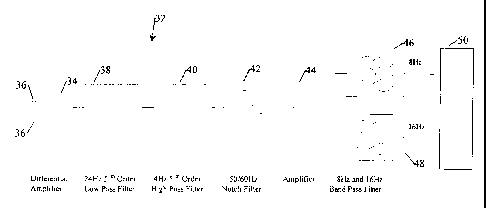
Figure 4 shows a ground probe 32 useful in practising the invention. This has
a
differential amplifier 34, used to amplify the voltage difference between
ground probe elements
36. Fifth order low pass and high pass filters 38, 40 are used to remove out
of band noise.
These are set at 24Hz and 4Hz respectively. A notch filter 42 is also used to
remove mains
power primary frequencies, at for example either 50Hz or 60Hz. The resulting
signal is
amplified at amplifier 44 and fed through two band pass filters 46, 48 to
isolate the 8Hz and
16Hz signal components. A delay equaliser (not shown) is used to compensate
for phase shift
between the signals as a result of the processing.
Once the 8Hz and 16Hz signals are acquired, they are processed by a processor
50.
In order to obtain polarity information from the so extracted waveforms
without using
phase deviation and its inherent problems with noise immunity, the 8Hz signal
is first rectified.
Next it is array multiplied with the 16Hz signal.
The multiplication is element-by-element in the following manner:
CA 02381364 2002-02-07
WO 01/13132 PCT/AUOO/00964
-9-
[a,,aZ,a3,a4...]*[bõb,,b3,b4...] = [a,*b,,a,*b2,a3*b3,a4*b4...]
where a. and b,, are respective time spaced samples of the rectified 8Hz
signal and the 16Hz
signal.
The resulting signal shows a reproducible characteristic with the mean offset
being in
the direction of the 16Hz signal peak which is closest to the 8Hz signal peak.
This characteristic
may be stable with nearly 90 degrees of phase shift in the 16Hz signal. This
is a substantial
improvement over the phase deviation methods. Figure 5 illustrates these
manipulations.
It is noted that there is an obvious ratio between the maximum negative
excursion and
the maximum positive excursion. This is at around 1:4. There is also a natural
ratio between
the mean and the maximum positive excursion. This is around 1:6. By applying
these metrics
to the acquired signal it is possible to deduce the likelihood that the signal
has only good
components.
Also, if a switching transient does occur, there will be expected to be a
substantial
discrepancy in the metrics. If all signals that exceed the peak to mean ratio
are clipped, and the
metric re-run, then the influence of the positive peak will be expected to be
reduced and no
longer cause an excessive contribution to the mean calculation.
Figure 6 shows the above-mentioned rectified and array multiplied signal in
the case
where this includes a large interfering peak.
The mean in this case is very slightly negative, although the mean for just
the signal
components that are part of the transmitted waveform would be expected to be
positive. Figure
7 shows the signal after the metric has been run and the peak excursions
clipped. As can be
seen, the mean is now positive, and the effect of the interference has been
overcome.
It is also possible to use the metric to eliminate results that are so heavily
distorted that
they cannot be successfully corrected. This lessens the problem of giving the
operator a
CA 02381364 2002-02-07
WO 01/13132 PCT/AUOO/00964
- 10-
misleading result which the operator must otherwise recognise and ignore. The
unit may do that
for the operator, and at least substantially avoid providing spurious data.
Because the mean of the array multiplied signal is known, both before and
after the
clipping, the ratio of these means can be used to gain confidence in the
direction indication. If
the ratio is close to one, then the original signal conformed fairly well to
the target metric and
is likely to be good. If the ratio is high, then confidence is reduced as the
original signal did not
fit the profile very well.
In addition, the ratio of the peak to the mean is also well defined. If this
is within
allowed limits before and after the clipping then confidence is high. If the
ratio was outside the
limits before clipping but came back into line after clipping, then confidence
is less. If the ratio
is poor for both cases then confidence is low.
For example, start with confidence = 100%.
1. If the peak to mean ratio before clipping was more than 20, and the target
was
6, then reduce confidence by 50%, otherwise if the ratio was 10 then reduce
confidence by 25%.
2. Now clip the signal. If the new peak on mean ratio is more than 20, then
half the
confidence, otherwise if it is more than 10, then reduce confidence to 3/4 of
the previous amount.
3. Now divide the peak on mean ratio before clipping by the peak or. mean
ratio
after clipping. If this ratio is more than 3 then reduce confidence by'/2,
else if it is greater than
2, then reduce confidence to 3/4 of the previous value.
At the end of this, a final confidence interval is reached. For a good clean
signal,
confidence will be 100%. This is as expected. If the signal was clean enough
after clipping but
a bit dirty beforehand, confidence will be 75%, and so on. This process can be
extended to any
number of steps depending on the complexity of the metric. The exemplary
thresholds given
here have been found satisfactory for the waveform and metric used as an
example of the
method. Once the confidence falls to a low enough level, ie < 33%, then
declaring results may
be stopped as the results are almost certainly unreliable.
CA 02381364 2002-02-07
WO 01/13132 PCT/AUOO/00964
- 11 -
Although a specific implementation is described here in order to properly
explain the
invention, other enhancements are also possible.
The transmitted power can be increased without increasing the peak voltage
excursion
of the waveform by altering the phase relationships between the waveforms.
Figure 8 illustrates
this. As can be seen, the peak excursion of the second waveform is symmetrical
at about +/-
1.8, whereas the initial waveform has a peak positive excursion of 2. Both
have a DC average
of zero. The receiver must realign the phases again to ensure the metrics
still work but this is
simple to do.
The example implementation here employs a mixture of analog and digital
processing.
The selection of which part of the process is done in which way is a matter of
design choice.
Metrics may be done using analog circuitry, and the filtering could also be
done digitally with
A/D sampling earlier in the chain. The choice of signal processing method is
not critical to the
implementation of the improved method for finding the sheath fault location.
Although this implementation only uses two frequencies, it is possible to
extend the
methods used to multiple frequencies and similar metrics across these
frequencies in groups of
two or more at a time.
In additional to measuring basic waveform metrics such as peak to mean ratio,
other
more complex metrics can be applied, such as least squares fit to a target
waveform. The
specific choice of metrics is a compromise between ease of computation and
likelihood that
error detection will be improved by adding the metric. The examples given here
have been
demonstrated to work satisfactory for a ground based sheath fault locator.
Averaging a number of results can further reduce spurious readings. The
results can
either be averaged when initially collected or else averaged after processing.
There are some
advantages of post processing averaging as only the better results get
included in the average.
Use of spurious results should obviously be avoided. The confidence factor can
also be used
to create a weighted average where the higher confidence results have more
bearing on the final
CA 02381364 2004-06-17
-12-
result than the lower confidence results.
Figures 9 to 11 are flow charts illustrating software executed steps in an
exemplary
device constructed in accordance with the invention.
Figure 9 shows steps in acquiring data samples of received signal. In samples
are
acquired at a 256 Hz sample rate, 64 samples being acquired for each overall
program
execution. This provides 250 mseconds of data or two complete cycles of the 8
Hz
waveform.
Execution of the data acquisition steps as illustrated in Figure 9 begins by
setting a
timer for 256 Hz, at step 102, followed by clearing of buffers and a counter
at steps 104,
106. Thereafter at step 108, the program awaits the timer, and then reads the
8 Hz and then
the 16 Hz signal at steps 110, 112. At the next step, step 114, a counter is
incremented by
one step and at the following step 116 a determination is made as to whether
the count
incremented at step 114 has reached 64. If it has not reached 64, steps 108
through to 116
are repeated, this being so repeated until the count reaches 64 after which,
at step 118
acquisition is complete.
In the steps illustrated at Figure 10, the 64 data points for each of the 8
and 16 Hz
signals as acquired by the process steps shown in Figure 9 are processed.
First, at steps
120, 122, 124, mean, and peak counter registers are cleared. Then, for the
first data point
acquired, the multiplication of the absolute value of the 8 Hz signal together
with the 16
Hz signal is computed, at step 126, to which a mean figure, comprising a
previous mean,
plus the result of step 126 is computed, this being executed at step 128.
After this, at step
130, comparison of the absolute value of the result of step 126 is made with
that of a peak
value (initially zero) and if that absolute value is greater than the peak,
the peak is, at step
132, updated to reflect the absolute value of the result of step 126. Next, a
counter initially
set to zero is incremented one step, this being effected at step 134. Then, at
step 136, it is
determined whether the counter has reached a stored count of 64. If it has
not, steps 126
through 136 are repeated, this repeating being effected until the count
reaches 64 after
which at step 138 there is computed a mean value representing the mean
accumulated by
the repeated executions of step 128 divided by 64. After that, at step 140,
signal
processing is judged complete.
CA 02381364 2002-02-07
WO 01/13132 PCT/AUOO/00964
- 13 -
Figure 11 shows program steps for determining a metrics calculation. First, at
step 150,
the ratio of the peak value to the mean value as computed at steps 132 and 138
is computed.
Then, at step 152, an expected peak value is set as the absolute value of the
mean computed at
step 138 multiplied by six. The program execution of this part of the program
is completed after
this, at step 154.
Figure 12 illustrates steps in effecting clipping of results according to
expected peak
result. At step 160, a counter is cleared. Then, at step 162, a comparison is
made between the
absolute value of the result, as computed at step 126, and an expected peak
value. If the
absolute value of the result is greater than the expected peak, it is then
determined whether the
result value is less than zero. If not, the result is set to the expected
peak, at step 166; otherwise
it is set to the negative of the expected peak at step 172 (described later).
If, at step 162, the
absolute value of the result is not greater than the expected peak, steps 164
and 166 and 172 are
skipped and the program moves to step 168. Program execution precedes from
step 166 or step
172 also to step 168, which is to increment the counter. At step 170, it is
determined whether
the count in the counter has reached 64. If not, program steps 162 and 164
and, if appropriate,
one or more of steps 166 or 172, are repeated as before described. Otherwise,
results clipping
is completed at step 174.
Figure 13 illustrates program steps in computing confidence results, including
the steps
described in the flow charts of Figures 9, 10, 11 and 12.
Firstly, at steps 180, 182 and 184, the steps illustrated respectively by the
flow charts of
Figures 9, 10 and 11 are effected. At steps 186, 188 mean #1 and ratio #1
values are set to the
mean and ratio value respectively, as computed previously, and results
clipping then occurs at
step 190, in accordance with the flow diagram of Figure 12. Subsequently, at
steps 192, 194
mean #2 and ratio #2 are set to the resultant values of mean and ratio
determined at step 190.
Then, at step 196, a confidence value is set to 100% and, subsequently, at
step 198, a
determination is made as to whether the value of ratio #1 is greater than 10.
If it is greater, at
step 200 it is determined whether ratio #1 exceeds 20. If so, the confidence
value is set to
confidence *0.5 at step 202, after which processing proceeds to step 2041ater
described. In the
CA 02381364 2002-02-07
WO 01/13132 PCT/AUOO/00964
- 14-
event that the result of the comparison of step 198 should be that the ratio #
1 is not greater than
10, program execution likewise proceeds at once to step 204. If, at step 200,
the ratio # 1 is
determined as not being greater than 20, then at step 205, the confidence
value is set to
confidence *0.75, after which program execution again continues at step 204.
At steps 204,
206, 208, 212 program steps corresponding to steps 198, 200, 202 and 205
respectively are
performed with respect to ratio #2 after which program execution continues at
step 210. At step
210, a ratio #3 is computed by dividing the ratio # 1 by the ratio #2 value
after which program
execution continues at step 214. At steps 214, 216, 218 and 222, program steps
again
corresponding to steps 198, 200, 202, 205 are performed with respect to the
ratio #3, after which
program execution terminates at step 220, at which confidence calculation is
effected.
Figures 14 to 16 show the physical configuration of the fault location device
32. this has
a casing 240 with an upper handle 242. Electrical components 246 are housed
within the casing.
The probes 24a, 24b project in spaced relationship from a framework 248
forming part of casing
240. Controls 250 for operating the device 32 are positioned at an upper part
of the housing
240.
The described arrangement has been advanced merely by way of explanation and
many
modifications may be made thereto without departing from the spirit and scope
of the invention
which includes every novel feature and combination of novel features herein
disclosed.
Throughout this specification and the claims which follow, unless the context
requires
otherwise, the word "comprise", and variations such as "comprises" and
"comprising", will be
understood to imply the inclusion of a stated integer or step or group of
integers or steps but not
the exclusion of any other integer or step or group of integers or steps.
The reference to any prior art in this specification is not, and should not be
taken as, an
acknowledgment or any form of suggestion that that prior art forms part of the
common general
knowledge in Australia.