Note: Descriptions are shown in the official language in which they were submitted.
CA 02381673 2002-03-06
WO 01/19282 PCT/AUOO/01080
- 1 -
IIRINE COLLECTOR
The present invention relates to a urine collector for
collecting the urine of female quadrupeds, of particular
but by no means limited application for the collection of
the urine of mares.
Devices for collecting, at the point of excretion, the
faeces or urine of various animals have been used for some
years for both sanitary purposes but also to facilitate the
reuse of the excrement. This practice has become
particularly significant owing to the recognition that this
excrement may contain valuable components, such as hormones
of value in the preparation of some pharmaceuticals.
Urine, in particular, has proved to be a remarkably rich
source of such hormones, which has prompted the development
of urine collectors. This is a relatively straightforward
matter for male animals but considerably more difficult for
female animals, especially if the urine is to be kept free
of faecal matter. As the urine of a pregnant mare, for
example, has been found to have particularly valuable
constituents, a number of known devices attempt to collect
such urine as conveniently, efficiently and contaminant
free as possible.
In their simplest form, a urine collector may comprise a
simple receptacle located behind the animal, and relying on
the force of urination to carry the urine to the
receptacle. Faeces tend to be ejected less forcefully, so
drop - in such collectors - between the animal and the
urine collector. However, in some cases faecal matter may
be ejected with such force that some faecal matter may
reach the urine collector, even if the aperture of the
urine collector is covered with a mesh to exclude large
portions of faecal solids. Even if the faecal solids are
stopped by such a mesh, the mesh will become contaminated
such that urine subsequently directed towards the collector
CA 02381673 2002-03-06
WO 01/19282 PCT/AUOO/01080
- 2 -
will become contaminated as it flows through the mesh and
into the collector. in addition, faecal fluid emitted by
the anus may run over the urethra during urination and
thereby contaminating the urine stream.
US Patent No. 3036553 teaches a collector tube for urine
and adaptor therefor, in which a vulva-encircling oval ring
is held in position against the animal by means of a
harness, with a fluid-tight bag attached to the oval ring
in which accumulates the collected urine. The oval ring
must form a strong contact with the animal between the
vulva and the anus to exclude faecal matter. The harness,
which engages the animal, also supports the fluid-tight
bag. The oval ring, however, is of relatively rigid
material and therefore is easily dislodged from its ideal
position when the animal moves about a stable or paddock,
or pushes its rump up against a tree or fence. Further, an
oval ring of any particular size can be used with only a
limited range of animals, as different animals differ in
the size of their vulva, the distance between their
buttocks, and the distance between the anus and vulva.
Variation in the last distance, between anus and vulva,
causes particular difficulties as the ability of this
device to exclude faecal matter is highly dependent upon
the correct locating of the device firmly against the
perineum. As a result, leakage and rubbing may result if
this device is used with a mare with a vulva at the upper
or lower end of the mean vulva size. This problem may be
overcome by custom-fitting each animal, but this adds
expense to the manufacturing process and is undesirably
time consuming.
There is also little resistance to the sideways movement of
the device, which therefore readily becomes dislodged from
its most effective position. Finally, even under ideal
circumstances this device performs poorly in excluding
faecal fluid, which is generally omitted from the anus
CA 02381673 2002-03-06
WO 01/19282 PCT/AUOO/01080
- 3 -
after solid faecal matter, and which runs down from the
anus along the animal's hide.
US Patent No. 3270714 discloses a similar device, which
attempts to overcome some of the deficiencies of that of US
Patent No. 3036553, by providing an outlet tube to the
collection bag and tethering this tube between the legs of
the animal to discharge forward of the animal. As a
result, this device reduces to some extent unwanted lateral
movement of the oval ring, but is only suitable for use
with a stabled animal. The device of this patent, in other
respects, shares the shortcomings of the device of US
Patent No. 3036553.
It is an object of the present invention, therefore, to
provide a urine collector for female quadrupeds which in
use will resist dislodgment and reduce the risk of faecal
contamination without undue discomfort to the animal.
Accordingly, the present invention provides a urine
collector for collecting urine from a female quadruped,
having:
a urine receptacle having a urine inlet for
receiving urine;
a support member for supporting said receptacle,
said support member locatable to bridge the buttocks of
said quadruped adjacent to and below the vulva thereof and
generally conforming to the shape of the rump of said
quadruped to thereby resist lateral displacement;
wherein said receptacle is supported by said
support member so that said urine inlet is proximate to and
substantially surrounds the periphery of the urethra of
said quadruped.
Thus, the urine collector of the present invention does not
need to surround the entire vulva, or form an effective
seal against the perineum, as it employs a receptacle
CA 02381673 2005-03-14
- 4 -
located around the urethra itself, and therefore at a
greater distance from the anus than in prior art devices
such as those of the above mentioned US patents. Some
faeces may be deflected by the top of the receptacle, but
- as the support member carries the weight of the
receptacle remote from the vulva - the receptacle will
exert little if any pressure on the vulva. The urine
collector may be attached to the quadruped by any suitable
known means, such as a suitable harness, such that the
urine collector - including most importantly the support
member - is located in the desired position.
Further, the vulva of the quadruped is used as a natural
barrier to deflect manure over the top of the urine
receptacle or chamber which itself is minimise in size as
it is only required to surround the urethra and not the
entire vulva.
Preferably the urine collector includes first and second
flexible panels for locating against the respective
buttocks of the quadruped and attached to said receptacle,
to further restrict unwanted movement of said receptacle
and to aid the locating of said receptacle adjacent to
said urethra. The first and second panels may be integral
with each other.
Preferably said receptacle is of a flexible construction.
Thus, it is desirable that the receptacle be of a flexible
material to reduce the risk of injury to the quadruped.
Urine may be accumulated in the receptacle, but preferably
the urine collector includes a reservoir and the
receptacle includes a urine outlet in fluid communication
with the reservoir.
Thus, the receptacle will not have to bear the weight of
CA 02381673 2002-03-06
WO 01/19282 PCT/AUOO/01080
- 5 -
the urine and may be compact in size.
Preferably said urine outlet is provided in a lower wall of
said receptacle.
Preferably said receptacle is located by said support
member to leave a passage between that portion of said
receptacle below said urine inlet on the one hand and said
support member and said vulva on the other hand, to allow
the passage of faecal fluid flowing down the hide of said
quadruped.
Thus, as faecal fluid will flow down the rump of the
quadruped rather than be projected rearwardly, a small
passage between the support member will allow this faecal
fluid (which may contain some faecal solids) to pass and
prevent its build up. The passage should be sufficiently
large that faecal fluid is substantially prevented from
entering the receptacle, but not so large that urine is
lost as it crosses the resulting gap between the urethra
and fluid inlet. Preferably, therefore, this gap is
between 2 cm and 4 cm, and more preferably about 3 cm.
That portion of the receptacle above the fluid inlet,
however, should remain adjacent to the vulva so that faecal
matter is prevented from entering the receptacle, as
discussed above.
Providing this passage may lead to the loss of a small
volume of urine, but the significance of the loss of volume
will be greatly outweighed by the preservation of the
purity of the collected urine.
The receptacle preferably has a top portion comprising a
roof for inhibiting falling faecal matter from entering
said receptacle. Preferably said roof has an underside
provided with a ridge to encourage faecal fluid to detach
from said underside and thereby not flow into said inlet,
PCT/AU00/0108U
CA 02381673 2002-03-06 Received 26 October 2001
- 6 -
and/or to direct flow of faecal fluid away from said inlet.
Preferably said support member has a central portion that,
in use, is lower relative to the urethra of said quadruped
than are portions of said support member adjacent to said
central portion.
Preferably said central portion is between 3 and 4 cm
lower, and more preferably approximately 3.2 cm lower.
This is to reduce the likelihood of the flow of downwardly
directed urine being partially interrupted by the support
member. However, this central portion may not be the only
central portion of the support means: the central portion
may be a first central portion in use distal from the mare,
and the support means may have a second central portion in
use proximate to the mare at substantially the same height
as the adjacent portions.
The present invention also provides a method of collecting
urine from a female quadruped, involving:
supporting a urine receptacle, having a urine
inlet for receiving urine, so that said urine inlet is
proximate to and substantially surrounds the periphery of
the urethra of said quadruped, without said urine
receptacle bearing significantly against said quadruped.
Preferably said method includes supporting said urine
receptacle by means of a support member locatable to bridge
the buttocks of said quadruped adjacent to and below the
vulva of said quadruped and generally conforming to the
shape of the rump of said quadruped to resist lateral
displacement therefrom.
Preferably the method includes locating said receptacle by
means of said support member to leave a passage between
that portion of said receptacle below said urine inlet on
the one hand and said support member and said vulva on the
AMEoEDE SHEET
PENAU
CA 02381673 2002-03-06
WO 01/19282 PCT/AUOO/01080
- 7 -
other hand, to allow the passage of faecal fluid flowing
down the hide of said quadruped.
Preferably said method includes inhibiting falling faecal
matter from entering said receptacle by providing said
receptacle with a top portion comprising a roof.
Preferably said method includes providing said roof on an
underside thereof with a ridge to encourage faecal fluid to
detach from said underside and thereby not flow into said
inlet and/or to direct flow of faecal fluid away from said
inlet.
Preferred embodiments of the present invention will now be
described, by way of example, with reference to the
accompanying drawings in which:
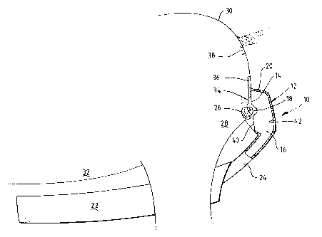
Figure 1 is a schematic view of a urine collector
for a mare, in simplified form, according to the preferred
embodiment of the present invention and shown in use with
the hindquarters of a mare;
Figure 2 is a view of the urine collector of
Figure 1, in use, from the rear of the mare;
Figure 3 is a detail of a preferred form of the
urine collector of Figure 1;
Figure 4 is a perspective view of a urine
collector according to another preferred embodiment of the
present invention;
Figure 5 is a front view of the urine collector
of Figure 4;
Figure 6 is a rear view of the urine collector of
Figure 4;
Figure 7 is a side view of the urine collector of
Figure 4;
Figure 8 is a view similar to that of Figure 7,
in partial cross-section;
Figure 9 is a view similar to that of Figure 7 in
full cross-section;
Figure 10 is a rear/side perspective view of the
CA 02381673 2002-03-06
WO 01/19282 PCT/AUOO/01080
- 8 -
urine collector of Figure 4;
Figure 11 is a bottom view of the urine collector
of Figure 4;
Figure 12 is a top view of the urine collector of
Figure 4;
Figure 13 is a top view of the standoff of the
urine collector of figure 4;
Figure 14 is a top view of the standoff and
receptacle of the urine collector of figure 4 in use;
Figure 15 is a bottom view of the standoff and
receptacle of the urine collector of figure 4 in use; and
Figure 16 is a perspective view of a urine
receptacle according to another preferred embodiment of the
present invention;
Figure 17 is a cross section through 17-17 in
figure 16, of the urine receptacle of figure 16; and
Figure 18 is a cross section through 18-18 in
figure 17, of the urine receptacle of figure 16.
A simplified urine collector according to a preferred
embodiment of the present invention is depicted, in use
with a mare 30, at 10 in Figure 1. Urine collector 10
includes a PVC receptacle 12 with a forward facing urine
inlet 14 and a urine outlet 16.
in addition, the receptacle 12 has a roof or lid 20, to
prevent (principally) faeces falling into the urine
collector 10.
Urine collector 10 also includes a reservoir 22 connected
to the receptacle 12 by means of tube 24, and a support
means in the form of rigid rubber standoff member 26,
conforming to the anatomy of the rump 28 of the mare 30,
and from which the receptacle 12 is suspended.
Not shown in Figure 1 is a fastening means or harness for
locating rubber standoff 26 in position and supporting
CA 02381673 2002-03-06
WO 01/19282 PCT/AUOO/01080
- 9 -
reservoir 22 under the belly 32 of the mare 30. This
harness, however, can be of any suitable form, although a
preferred form will be described in greater detail below
(see figure 4).
The size of the receptacle 12 is such that the receptacle
12 extends above the rubber standoff 26 so that urine inlet
14 surrounds the urethra 34 of the mare 30. The receptacle
12, in particular, does not attempt to encircle the entire
vulva 36. The roof 20 is provided so that faeces ejected
from anus 38 are prevented from entering receptacle 12.
Further, a passage 18 is left between portion of the
receptacle 12 below the urine inlet 14 on the one hand and
the standoff 26 and vulva 36 on the other hand, so that
faecal fluid emitted from anus 38 may run down the mare and
between the receptacle 12 and the standoff 26. Roof 20 of
receptacle 12, however, preferably makes light contact with
the vulva 36 so that falling faecal solids are excluded
without causing discomfort to the mare 30. Urine ejected,
typically with some force, from urethra 34 will cross the
passage 18 and hit inside rear face 42 of receptacle 12 and
be directed downwards into tube 24 to reservoir 22. Some
urine, possibly ejected with less force, may be lost into
the passage 18, but this will represent a small proportion
of the total urine emitted and it is preferable that a
small quantity of urine be lost than that the collected
urine be contaminated by faecal fluid.
Figure 2 is a rear schematic view of a portion of the urine
collector 10 of figure 1, showing the relative location of
the rubber standoff 26, receptacle 1 and tube 24 of the
urine collector with respect to the vulva 36 and urethra 34
of the mare 30. It should be understood that the rubber
standoff 26 is indented towards its centre and ends to
conform to the curve of the rump 28 of mare 30. The ends
of the rubber standoff 26 thereby wrap around the rump 28
to some extent. The result is that rubber standoff 26 is
CA 02381673 2002-03-06
WO 01/19282 PCT/AUOO/01080
- 10 -
shaped somewhat like the numeral "3", thereby strongly
inhibiting any undesired lateral movement of the rubber
standoff 26. The receptacle 12 is thus held securely about
the urethra 34, without itself having to be pressed firmly
against the rump 28 or vulva 36 of the mare 30. As
discussed above, there will generally be some contact
between the receptacle 12 and the mare 30 (by virtue of the
roof 20), but the receptacle is constructed of a soft,
flexible material so that any such contact does negligible
or no harm to the mare 30.
In a preferred form of the embodiment depicted figure 1,
the urine collector includes a pair of flexible PVC panels,
which cover the rump 28 of the mare 30 and are attached to
both the rubber standoff 26 and the receptacle 12. These
panels are represented in figure 3 at 44 and 46. The urine
collector also includes straps 48 for attaching the PVC
panels 44, 46 and the receptacle 12 to the rubber standoff
26. These PVC panels 44, 46, as they rest against the rump
28 of the mare 30, are constrained to conform to the shape
of rump 28. Consequently, by attaching receptacle 12 to
these PVC panels 44, 46, the receptacle 12 can be
accurately located about the urethra 34 without making any
significant contact with vulva 36 or rump 28 of the mare
30.
The combination, in use, of the rubber standoff 26 and PVC
panels 44, 46, securely locates the receptacle 12 about the
urethra 34, making as little contact as possible with the
mare 30.
Figure 4 is a more detailed, perspective view of a still
further preferred urine collector 50, which is essentially
a preferred form of urine collector 10. This figure
clearly shows the urine receptacle 52 mounted, by means of
straps 54, to rubber standoff 56. Flexible PVC panels 58
and 60 (as discussed above) are provided to ensure the
CA 02381673 2002-03-06
WO 01/19282 PCT/AUOO/01080
- 11 -
correct locating of receptacle 52. Reservoir 62 includes a
bladder (not shown) for accumulating urine, and in fluid
communication by means of a tube (not shown) to the urine
outlet (not shown) of receptacle 52. The reservoir 62 also
includes an outlet port 64 for emptying the reservoir 62.
Various fastening points 66a are provided at the upper side
of reservoir 62, so that the urine collector 50 may be
strapped to the mare. Similar fasteners 66b are provided
in the upper section of the urine collector 50 for the same
purpose.
The flexible panels of urine collector 50, as well as the
other portions of the harness for maintaining the urine
receptacle and rubber standoff 56 in position, may instead
be made of diaphragm rubber (or nylon insertion rubber),
comprising rubber sheet in which is imbedded a nylon web.
Cold conditions favour the production of a higher
concentration of the desired hormones in a mare's urine,
and rubber is less vulnerable to becoming hard, brittle or
uncomfortable when cold than is PVC.
This figure also clearly shows the indented or pointed
central portion 68 of rubber standoff 56 which, in use,
sits between the mares legs under the vulva. This pointed
portion 68 correctly locates the rubber standoff 56 (and
therefore the receptacle 52) by inhibiting sideways
movement of the rubber standoff 56.
The urine collector 50 also includes a manure chamber 70,
which is a simple shoot with an open lower end so that
manure, ejected from the anus of the mare, can pass over
and behind urine receptacle 52 and fall from the urine
collector 50 under the ground (or into some receptacle, as
desired).
in figures 4 to 12, which are all alternative views of the
urine collector 50 of figure 4, like numerals refer to like
CA 02381673 2002-03-06
WO 01/19282 PCT/AUOO/01080
- 12 -
features.
Figure 5 is a front view of the urine collector 50 of
figure 4. This figure more clearly depicts the upper
portion 72 of the urine collector 50, which comprises an
open weave fabric for locating above the tail of the mare
and providing support for the urine collector 50.
Figure 6 is a rear view of the urine collector 50 of figure
4. In this view, the tube 74 between the receptacle 52 and
the reservoir 62 is shown, as well as the exit aperture 76
of the manure chamber 70.
Figure 7 is a side view of urine collector 50, while figure
8 is a partial cross-section of the view of figure 7, and
figure 9 is a full cross-section of the view of figure 7,
in which is shown bladder 82 in reservoir 62.
Figure 10 is a rear/side perspective view of the urine
collector 50, while Figures 11 and 12 are - respectively -
bottom and top views of urine collector 50.
Referring to Figure 13, the rubber standoff 56 of the urine
collector 50 is shown, from above, together with rearwardly
projecting arms 78 and 80. The arms 78 and 80 hold open
the manure chamber 70 so that it does not collapse under
its own weight.
Figure 14 is a top view of rubber standoff 56 with
receptacle 52, relative to the vulva 36 and urethra 34. It
will be seen that vulva 36 actually overhangs part of the
central section of rubber standoff 56, and that roof 82 of
urine receptacle 52 just makes contact with vulva 36.
Figure 15 is a bottom view of rubber standoff 56 and
receptacle 52 of urine collector 50, relative to vulva 36
and urethra 34. From underneath, the vulva 36 is partially
CA 02381673 2002-03-06
WO 01/19282 PCT/AUOO/01080
- 13 -
obscured by the rubber standoff 56. Roof 82 projects to
the vulva 36, but it will be seen that a passage 84 is left
between the main body of urine receptacle 52 and the vulva
36 to allow faecal fluid to escape. This faecal fluid can
pass roof 82 owing to the fact that roof 82 does not form a
firm seal with or exert great pressure against vulva 36.
Such fluid can flow down passage 84 and escape.
A percentage of mares have a urine stream that is close to
vertically downwards. Some mares will squat particularly
low to avoid urine splashing on them owing to, for example,
high winds, which can also cause the urine stream to be
closer to the vertical. Such a urine stream may hit the
rubber standoff (or cross member) 56, and be deflected
thereby out of the collector. Thus, an unbroken flow of
urine may not enter the urine receptacle 52.
One solution might be to lower the standoff 56 to avoid the
urine stream, but the urine collector will then move
backwards as the mare squats, and the rubber standoff 56
nonetheless move into the urine stream. For this reason,
in fact, it is generally important that the rubber standoff
56 be close to the vulva 36 and urethra 34 so that there is
minimal backward movement of the standoff 56.
Thus, it may be preferably to configure the rubber standoff
56 to accommodate such downward urination. This can be
done by lowering or thinning the central portion 68 of the
standoff 56 on its concave, rearward facing side, and
thereby introducing a greater gap between the urethra 34
and the standoff 56. This can be done either by stepping
the standoff 56 at the upper, rearward edge of the central
portion 68, or forming the two lateral halves of the
standoff 56 with a central gap, the two halves joined with
a lowered central portion 68. In either case, the top of
the central portion 68 closest to the urethra 34 is
lowered, preferably by about 3 to 4 cm and, in one
CA 02381673 2002-03-06
WO 01/19282 PCT/AUOO/01080
- 14 -
preferred embodiment, by 3.2 cm.
This adjustment increases the likelihood that downward
urination will avoid the rubber standoff 56.
Figure 16 is a perspective view of a rubber urine
receptacle 90 according to another preferred embodiment of
the present invention. Urine receptacle 90 is comparable
to urine receptacle 52 of urine collector 50 (see figure
4), but includes a number of further refinements.
Receptacle 90 is integrally moulded in soft rubber so that,
where it is in contact with the rump of a mare, little if
any rubbing or chaffing will occur. The receptacle 90 has
a urine inlet 92 and a urine outlet 94 (to which urine is
constrained to flow by receptacle 90 after the urine has
entered inlet 92). Urine that enters inlet 92 flows
towards outlet 94 and from there along suitable tubing to a
reservoir (as described above).
Receptacle 90 is provided with laterally extending wings
96a and 96b disposed either side of inlet 92 to distribute
any pressure that may, in use, be exerted by the receptacle
90 against the mare's rump.
Thus, to this point receptacle 90 resembles receptacle 52
of figure 4, and operates according to the invention when
inlet 92 is disposed about the mare's vulva in the manner
described above.
However, urine discharged by the mare may enter inlet 92
and thereby receptacle 90 with considerable velocity. In
order to minimize the risk of the urine splashing out of
receptacle 90 (rather than flowing towards outlet 94),
receptacle 90 has side walls 98a and 98b that distend
outwardly, forming vertically elongate channels concave to
the interior of receptacle 90. The channel formed by
CA 02381673 2002-03-06
WO 01/19282 PCT/AUOO/01080
- 15 -
concave side wall 98b is also shown in figure 17, which is
a cross sectional view through 17-17 in figure 16 of
receptacle 90. Referring to figure 18, when receptacle 90
is viewed in cross section through 18-18 in Figure 17, the
concave nature of these channels formed by side walls 98a
and 98b becomes still more readily apparent. Indeed, these
channels face somewhat rearwardly towards rear wall 100 of
receptacle 90 so that urine deflected sideways into these
channels will tend to splash towards rear wall 100 rather
than towards inlet 92 (from which it might undesirably
escape).
Receptacle 90 includes a roof 102 (comparable to roof 82 of
receptacle 52) that is integral with rear wall 100 and, to
a lesser extent, side walls 98a and 98b. Roof 102 can
extend towards the mare's rump as far as possible without
actually touching the rump, to exclude as faecal matter
(solid and liquid) as possible. Being of soft rubber, any
inadvertent contact between roof 102 and the mare's rump
should lead to little if any injury to the mare. Thus, it
is acceptable to extend roof 102 closer to the mare's rump
than might otherwise be possible if contact of any kind
were intolerable (if, for example, the urine receptacle
were of a harder or more abrasive material). However,
owing to the softness of roof 102, there may be a tendency
for roof 102 to sag or otherwise become distorted, and
consequently function less efficiently at excluding faecal
matter. Accordingly, roof 102 is most desirably formed
with a strengthening ridge 104 along its mid-plane
(coinciding with cross sectional plane 17-17 in figure 16).
Roof 102 also includes a central extension 106, which
projects forwardly towards, in use, the mare's rump and
somewhat between the mare's buttocks. This further
optimizes the extent to which faecal matter is excluded
from the receptacle 90.
CA 02381673 2002-03-06
WO 01/19282 PCT/AUOO/01080
- 16 -
As discussed above, however, a certain quantity of faecal
fluid emitted from the anus may run over the mare's rump
and, potentially, enter inlet 92 of receptacle 90. Owing
to the proximity with which projection 106 can be located
to the mare, some of this faecal fluid may flow from the
mare onto roof 102 of the receptacle 90 and, flowing along
the underside of roof 102, enter receptacle 90.
Accordingly, roof 102 is provided with an elongate,
transversely disposed integral ridge 108 on the underside
of roof 102. Ridge 108 serves two functions: faecal fluid
reaching ridge 108 will be encouraged to detach itself from
roof 102 and, rather than flowing into inlet 92, fall past
inlet 92. This is more clearly apparent in figure 17, in
which plumb-line 110 illustrates the trajectory of faecal
fluid falling from ridge 108 onto the outside face of
forward wall 112. Such faecal fluid will then flow over
the outside surface of the receptacle 90, away from inlet
92 and so not be collected.
In addition, ridge 108 may, in some embodiments, be formed
in two lateral portions meeting at an obtuse angle in an
inverted, broad "v" at the mid-line of roof 102. Faecal
fluid will thereby be encouraged to flow away from this
mid-line so that, if the faecal fluid does not become
detached from roof 102 by means of ridge 108, it may
nevertheless still be excluded from collection by
ultimately falling to one side of inlet 92 or passing back
to the mare's rump owing to contact between the mare's rump
and roof 102.
Modifications within the spirit and scope of the invention
may be readily effected by a person skilled in the art, and
it is to be understood that this invention is not limited
to the particular embodiments described by way of example
hereinabove.