Note: Descriptions are shown in the official language in which they were submitted.
CA 02381726 2002-02-11
WO 01/19492 PCT/GBOO/03571
- 1 -
A SCREEN FOR USE IN A SHALE SHAKER AND METHOD FOR
USING SAME
The present invention relates to a screen for use in
a shale shaker and a method for using same.
Shale shakers have been used for many years to
separate particles in a wide array of industrial
applications. One common application for shale shakers is
in drilling operations to separate particles suspended in
drilling mud. If drilled solids are not removed from the
mud used during the drilling operation, re-circulation of
the drilled solids can create weight, viscosity, and gel
problems in the mud, as well as increasing wear on mud
pumps and other mechanical equipment used for drilling.
A shale shaker generally includes at least one
screen which is generally flat and mounted generally
horizontally on a vibrating mechanism or shaker that
imparts either a rapidly reciprocating linear, elliptical
or circular motion to the screen. A shale shaker may
comprise a series of screens arranged in tiered or flat
disposition with respect to each other. In use, the
vibrating mechanism vibrates the screen. Circulated
drilling mud is poured on to a back end of the vibrating
screen, usually from a pan mounted above the screen. The
material generally flows toward the front end of the
screen. Large particles are unable to pass through the
screen, remaining on top of the screen and moving toward
the front of the screen where they are collected. The
smaller particles and fluid flows through the screen and
collects in a pan beneath the screen.
A screen may have a fine screen cloth. The screen
may have two or more overlying layers of screen cloth.
The layers may be bonded together and be provided with a
support, supports, or a perforated or apertured plate
beneath the screen or screens. The frame of the
vibrating screen is resiliently suspended or mounted upon
1 1-uo- ut. 1
CA 02381726 2002-02-12 LD UUUUU00/1
2 -
a support and is caused to vibrate by a vibrating
mechanism, for example an unbalanced weight on a rotating
shaft connected to the frame. Each screen may be
vibrated by vibratory equipment to create a flow of
trapped solids on top surfaces of the screen for removal
and disposal of solids. The fineness or coarseness of
the mesh of a screen may vary depending upon mud flow
rate and the size of the solids to be removed.
Many screens used with shale shakers are flat or
nearly flat which are known as two-dimensional screens.
Other screens having corrugated, depressed, or raised
surfaces are three-dimensional. US-A-5,417,793, US-A-
5,417,858 and US-A-5,417,859 disclose non-flat screens
for use with shale shakers. These screens have a lower
planar apertured plate with a multiplicity of spaced-
apart apertures or openings therethrough. Undersides of
troughs of undulating screening material are bonded to
the apertured plate. Such screens present a variety of
problems, deficiencies, and disadvantages, including:
decreased flow area due to area occluded by solid parts
of the apertured plate; necessity to either purchase
relatively expensive apertured plate or provide for in-
house perforating of a solid plate; plate weight
increases wear on parts such as rubber screen supports or
cushions and can inhibit required vibration; large plate
surface area requires relatively large amount of bonding
means for bonding screens to the plate; and a finished
screen which is relatively heavy increases handling
problems, hazards, and cost of shipping. The screens also
have to be able to provide a throughput for a large
quantity of fluid. There are also problems involved with
the ease of manufacture of the screen assemblies.
According to the present invention, there is
provided a screen assembly for a shale shaker, the screen
assembly comprising at least two ridge-valley series of
AMENDED SHEET
11-06-2001 CA 02381726 2002-02-12 (b UUUUU3571
3 -
screening material comprised of a plurality of
alternating ridges and valleys of screening material,
characterised in that said screen assembly further
comprises at least one flat area of screening material
adjacent at least one of the ridge-valley series.
Other aspects of the invention are set out in claims
2 to 17.
The invention also provides a method for treating
fluid with a vibratory separator, the fluid having
material entrained therein to be separated therefrom, the
method comprising, introducing the fluid onto a screen
assembly in the vibratory separator, the screen assembly
comprising at least two ridge-valley series of screening
material comprised of a plurality of alternating ridges
and valleys of screening material, and at least one flat
area of screening material adjacent at least one of the
ridge-valley series, and separating material from the
fluid with the screen assembly. Preferably, the at least
one flat area of screening material is at a trailing end
of the screen assembly.
* * *
US-A-5,417,858 discloses a screen having a ridge
which is triangular in cross-section. The triangular
ridge is made from two overlying layers of screening
material. Two wing portions of screening material are
folded over an and of the ridge and welded together to
form a flat, vertical end to the ridge.
According to another aspect of the invention, there
is provided a screen assembly for a vibratory separator,
the screen assembly comprising a screen of undulating
screening material comprised of a plurality of
alternating ridges and valleys, said screen assembly
further comprising ridge ends at either end of said
plurality of alternating ridges and valleys, each ridge
end comprising a plurality of alternating ridges and
AMENDED SHEET
11-06-2001 CA 02381726 2002-02-12 GB 000003571
4 -
valleys of screening material having an integral portion
of screening material covering an end of said ridge and
characterised in that said portion of screening material
is moulded to form an end substantially free of seams.
Other aspects of the invention are set out in claims
21 to 27.
There is also provided a method for treating fluid
with a vibratory separator, the fluid having material
therein to be separated therefrom, the method comprising,
introducing the fluid onto a screen assembly in the
vibratory separator, the screen assembly comprising a
screen of undulating screening material comprised of a
plurality of alternating ridges and valleys, said screen
assembly further comprising ridge ends at either and of
said plurality of alternating ridges and valleys, each
ridge end comprising a plurality of alternating ridges
and valleys of screening material having an integral
portion of screening material covering an end of said
ridge end characterised in that said portion of screening
material is moulded to form an and substantially free of
seams, and separating material from the fluid with the
screen assembly. Preferably, the ridge ends are of a
generally bulbous shape.
AMENDED SHEET
CA 02381726 2002-02-11
WO 01/19492 PCT/GBOO/03571
-
For a better understanding of the invention,
reference will now be made, by way of example, to the
accompanying drawings, in which:
Figures 1A to 1D are perspective views of screens
5 according to the present invention;
Figure 1E is a top schematic view of a screen
according to the present invention;
Figure iF is a perspective view, of part of the
screen of Figure 1D taken along the line iF-iF, with
parts cut away;
Figure 1G is an end view of part of the screen of
Figure 1, taken along line 1G-1G;
Figure 2 is a perspective view of a screen according
to the present invention;
Figures 3A to 3C are perspective views of screens
according to the present invention; and
Figure 4A is a top plan view of a screen assembly
according to the present invention, with hidden parts
shown in dotted lines;
Figure 4B is an exploded end view of the screen
assembly of Figure 4A;
Figure 4C is an exploded cross-sectional view of the
screen assembly of Figure 4A;
Figure 5A is a top plan view of a screen component
blank of the screen of Figure 4A;
Figure 5B is an exploded view of the screen
component blank of Figure 5A;
Figure 5C is a side cross-section view of the screen
component of Figure 5A in corrugated form;
Figure 6A is a side cross-section view of a screen
component blank of the screen of Figure 4A;
Figure 6B is a top view of the screen component
blank of Figure 6A;
Figure 6C is a top view of the screen component of
Figure 6B with notches;
CA 02381726 2002-02-11
WO 01/19492 PCT/GBOO/03571
- 6 -
Figure 6D is a side plan view of the screen
component of Figure 6A with formed ridge ends;
Figure 6E shows the profile from the side of one of
the ridge ends of Figure 6D;
Figure 6F is a cross-section view of the screen
component of Figure 6D;
Figure 6G shows the screen component of Figure 6D
prior to end formation;
Figure 6G is a side view of the screen component
of Figure 6F.
Figure 7A is an exploded cross-section view of a
screen component blank of the screen assembly according
to the present invention;
Figures 7B and 7C are top views of screen components
according to the present invention with layers as shown
in Figure 7A;
Figure 8 is an exploded cross-section view of a
screen component for the screen assembly of Figure 4A;
Figure 9A is a cross-sectional view of a screen
component blank according to the present invention;
Figure 9B is a top plan view of a screen component
blank for a screen assembly of Figure 9A;
Figures 9C and 9D are exploded cross-sectional views
of part of the screen component blank of Figure 9B;
Figure 9E is a top view showing the screen component
of Figure 9A with notches therein;
Figure 9F is a side view that shows the screen
component of Figure 9E with formed ridge ends;
Figure 9G is a side view of the screen component of
Figure 9F;
Figure 9H is a side view of the screen component of
Figure 9E showing ridge end profiles;
Figure 10A is a cross-sectional view of an end
forming device;
Figure 10B is a cross-sectional view of the device
CA 02381726 2002-02-11
WO 01/19492 PCT/GBOO/03571
7 -
of Figure 10A;
Figure 10C is a top view of the device of Figure
10A, in use, with hidden parts shown in dotted lines;
Figure 10D is a side view of the device of Figure
lOB;
Figure 11A is a perspective view of a screen
assembly according to the present invention;
Figure 11B is a partial end view of the screen
assembly of Figure 11A;
Figures 11C to 11F are perspective views of parts of
the screen assembly of Figure 11A;
Figure 12A is a perspective view of a part of a
screen in accordance with the present invention;
Figure 12B is a top plan view of a blank of the part
of the screen of Figure 12A;
Figure 12C is a top plan view of the part of the
screen as shown in Figure 12A;
Figure 12D is an end view of the screen of Figure
12A.
Figure 1A shows a screen assembly 100 with two
offset series of ridges 1, 2 formed of screening
material. Any screening material or combination thereof
disclosed herein may be used or any disclosed in PCT
Publication Nos. WO 00/25942, WO 00/25943 or WO 00/25890.
Surrounding the ridge series 1, 2 are relatively flat
areas 3 to 6 of screening material, generally of.the same
type as that used for the ridges, thereby allowing
similar sized particles therethrough and having similar
mechanical properties, such as longevity. A flat
screening material area 7 separates the two series of
ridges 1, 2. Optionally, hookstrips 8 are provided on
two sides of the screen assembly 100. Although "C"
channel shaped hookstrips are shown, any suitable
hookstrip (angled, L shaped, etc.) may be used. In
certain aspects (and for any screen disclosed herein),
CA 02381726 2002-02-11
WO 01/19492 PCT/GBOO/03571
8 -
the ridge-valley series extend to the hookstrips and the
flat areas are eliminated.
A series of ridges la is interspersed between the
series of valleys or troughs lb. A second series of
ridges 2a and valleys 2b is offset from the ridges
la/valleys lb. As shown in Figure 1G the shape of one
set of ridges RD may overlap (when viewed on end) the
ridges RG of the other set of ridges. The ridges RD are
also the same size as the ridges RG, as are the valleys.
It is within the scope of this invention to employ any
desired amount of such overlap. The ridges are of
substantially the same height and ridge ends are of
substantially the same cross-sectional area. It is also
within the scope of this invention for the ridges of one
set of ridges to be of a different width than those of
the other set; for the one set to be wider or narrower
than the second set; for ridges or ridge ends on one set
to have a different cross-sectional area than those of
another set; and/or to employ three, four, five, six or
more series of offset ridges on a single screen.
Optional side paths 4 and 6 may be eliminated by having a
ridge edge or ridge adjacent a hook strip 8 side or
positioned against a frame side (when an optional frame
is used) or side member if hook strips are not used.
Figure 1B shows a screen assembly 10 with two offset
series of ridges 11, 12 formed of screening material.
Any screening material or combination thereof disclosed
herein may be used or any disclosed in PCT Publication
Nos. WO 00/25942, WO 00/25943 or WO 00/25890.
Surrounding the ridge series 11, 12 are relatively flat
areas 13 to 16 of screening material. A flat screening
material area 17 separates the two series of ridges 11,
12. Optionally, hookstrips 18 are provided on two sides
of the screen assembly 10. Although "C" channel shaped
hookstrips are shown, any suitable hookstrip (angled, L
CA 02381726 2002-02-11
WO 01/19492 PCT/GBOO/03571
- 9 -
shaped, etc.) may be used.
Figure 1C shows a screen assembly 20 with two offset
series of ridges 21, 22 formed of screening material.
Any screening material or combination thereof disclosed
herein may be used or any disclosed in PCT Publication
Nos. WO 00/25942, WO 00/25943 or WO 00/25890. Around the
ridge series 21, 22 are relatively flat areas 23, 24, 26
of screening material. Flat screening material area 27
separates the two series of ridges 21, 22. Optionally,
hookstrips 28 are provided on two sides of the screen
assembly 20. Although "C" channel shaped hookstrips are
shown, any suitable hookstrip (angled, L shaped, etc.)
may be used.
Figure 1D shows a screen assembly 30 with two offset
series of ridges 31, 32 formed of screening material.
Any screening material or combination thereof disclosed
herein may be used. Surrounding the ridge series 31, 32
are relatively flat areas 34, 35, 36 of screening
material. A flat screening material area 37 separates
the two series of ridges 31, 32. Optionally, hookstrips
38 are provided on two sides of the screen assembly 30.
Although "C" channel shaped hookstrips are shown, any
suitable hookstrip (angled, L shaped, etc.) may be used.
Figure iF shows a part of the screen assembly 30,
showing hook strips 38 on either side thereof. Screening
material SM is connected along the length of each hook
strip by known methods, for example folding, welding,
crimping together, epoxying, press/fiction fit, and/or
interlocking of parts. In one aspect no underlying
plate, straps, or strips and no frame are used with the
screen assembly 30.
The screening material SM may be any known
screening material, screen and/or mesh or combination
thereof and/or any screening material disclosed herein.
In the screen 30 as shown, the screening material SM
CA 02381726 2002-02-11
WO 01/19492 PCT/GBOO/03571
- 10 -
includes a lower mesh (for example 1 to 80 mesh) CM which
may be a relatively coarse mesh and an upper mesh FM (for
example 8 to 400 mesh) which may be a relatively fine
mesh. Two fine mesh screens and one coarse mesh screen
may also be used. The fine mesh may be bonded to the
coarse mesh, sewed to the coarse mesh, glued to it,
welded to it, and/or sintered to it.
An optional perforated plate or a series of straps
or strips such as those disclosed in WO 94/23849, may be
used below the coarse mesh. One, two, three or more
layers of wire mesh may be used instead of or with such a
plate, straps, or strips. In one particular aspect a
flat coarse mesh (for example mesh 1 to mesh 12) is used
instead of or in addition to a plate, straps, or strips.
Mesh (fine, coarse, or both) is folded over open
exposed ends of ridges ME. This mesh can be
substantially flat over the open ridge end or, as shown,
it can protrude as part of a bulb or closed curve shape.
Such shape can provide more screen area for separation
and can deflect and re-route solids and fluid to a
subsequent set of valleys. A fine screen may underlie the
coarse mesh, the fine mesh being hot-glued on to the
coarse mesh end and/or to the mesh ridge. Alternatively
any or all openings may be plugged with a solid, porous,
or perforated plug glued or welded in place.
Alternatively, instead of folding screening material
and/or mesh over the ends of ridges, a separate piece of
screen, screens, mesh, and/or meshes can be placed at an
open ridge end and the edges of the piece attached to,
connected to, interlocked with, interwoven with, and/or
adhered to the edges of the ridge end opening. Also, it
is within the scope of this invention for any ridge end
to be closed off to fluid flow, to be covered with
screen(s) and/or mesh, and/or to be plugged.
Figure 2 shows a screen assembly 40 with two offset
CA 02381726 2002-02-11
WO 01/19492 PCT/GBOO/03571
- 11 -
series of ridges 41, 42 formed of screening material.
Any screening material or combination thereof disclosed
herein may be used. Between the ridge series 41, 42 is a
relatively flat area 47 of screening material. Other flat
areas 43, 44, 45, 46 are provided on sides of the ridge
series. Optionally, hookstrips 48 are provided on two
sides of the screen assembly 40. Although "C" channel
shaped hookstrips are shown, any suitable hookstrip
(angled, L shaped, etc.) may be used. "Flat areas" are
to be understood as including screening material for
screening fluid flowing thereto. For any screen in
Figures 1A to 3C any ridge series or combination of ridge
series disclosed herein may be used. It is also to be
understood as within the scope of this invention to use
one or more of any of the relatively flat areas of
screening material discussed above with any screen
assembly or screen disclosed herein and/or with any
screen or screen assembly with one, two, three, four or
more series of ridges, offset or not, angled with respect
to each other or not, angled with respect to sides of a
frame, screen, or basket, or not (as viewed from above).
Figures 3 to 3C show screen assemblies according to the
present invention which employ two series of offset
ridges of screening material with one or more flat areas
of screening material and one or more series of ramp
screen portions as described in PCT Publication No. WO
00/25942. It is to be understood that the ridges,
valleys, flat areas, and ramps are made of screening
material or combinations of screening material,
including, but not limited to, any disclosed herein.
Figure 3A shows a screen 50 with two series of
screening material ridges 51, 52 spaced apart by a flat
area of screening material 57 with flat areas 53 to 56 on
sides of the series of ridges. A trailing and 59 of the
screen 50 has three screening material ramps 64 to 66.
CA 02381726 2002-02-11
WO 01/19492 PCT/GBOO/03571
- 12 -
Ramps for any screen disclosed herein may extend all the
way to the hookstrip sides of screen. Optional
hookstrips 58 are provided on two sides of the screen 50.
Flat areas of screening material 61, 62, 63 are adjacent
the ramp area.
Figure 3B shows a screen 70 with two series of
screening material ridges 71, 72 spaced apart by a flat
area of screening material 77 with flat areas 73 to 76 on
sides of the series of ridges. A trailing end 79 of the
screen 70 has three screening material ramps 84 to 86.
Optional hookstrips 78 are provided on two sides of the
screen 70. Flat areas of screening material 81, 82, 83
are adjacent the ramp area. A leading end 89 has three
screening material ramps 80, 87, 88 with adjacent flat
areas 91 to 93 like the areas 81 to 83.
Figure 3C shows a screen 200 like the screen 70 of
Figure 3B (and like numerals indicate the same parts),
but instead of the central flat area 77, the screen 200
has two central ramps of screening material 101, 102.
One, three, or more ramps may be used in this central
area (as may be used instead of the three ramp areas of
Figures 3A and 3B).
In alternative embodiments, any screen of Figures 1A
to 3C may have lower supporting relatively coarse mesh,
lower mesh or mesh layers, or a lower support frame,
apertured plate, perforated plate and/or strap member or
series of spaced-apart straps or strips.
For any of the screens of Figures 1A to 3C: all
ridge ends may be plugged with a solid plug or a
perforated plug; glued shut; all ends at or closest to a
leading screen end or a trailing screen end may be
sealingly closed and opposite ends of the ridge series
open, or vice versa; any (or all) ridge end may be
covered with screening material. In one particular
embodiment in the screens of Figures 1A to 3C, the first
CA 02381726 2002-02-11
WO 01/19492 PCT/GBOO/03571
- 13 -
ridge series (the one closest to a screen leading end, to
the left in each Figure) has its ridge ends closest to
the leading end of the screen assembly (the end at which
fluid is introduced) covered with screening material and
the other ends of the same ridges open, or vice-versa.
Alternatively all ridge ends are covered with screening
material. Screening material covering a ridge end may be
a separate piece connected to the ridge end edges or it
may be a continuation of the screening material forming
the ridge-valley series, folded over on the ridge end.
In certain aspects each of the screens in Figures 1A to
3C have no screening material below the ridge-valley
series or a coarse screen cloth below them. In other
aspects there is one or more layers of fine screening
material below the ridge-valley series so that the ridges
and the relatively flat screening material below the
ridges define a porous tube of screening material through
which fluid can flow. Fluid entering such a tube and
flowing therein for some distance can flow out the ridge
sides into a valley adjacent the ridge and then back into
the ridge's interior, and so on, and so on. For each
screen in Figures 1A to 3C and other screens disclosed
above the ridges as shown as following relatively
straight lines as viewed from above. But any such screen
may have ridges with an undulating shape as viewed from
above.
One example of a screen according to the present
invention with ridges with an undulating or curved shape
as viewed from above is shown in Figure 1E. A screen 30a
(like the screen 30 but for the ridges and flat areas)
has two series of offset ridges 31a and 32a. The ridges
(and therefore valleys 31b and 32b, respectively) have an
undulating shape as viewed from above. Any number of
ridges (wider or narrower than shown) may be used as may
be any number (one, two, three, four) of series of
CA 02381726 2002-02-11
WO 01/19492 PCT/GBOO/03571
- 14 -
ridges. Alternatively one series of ridges is not offset
from an adjacent series.
Figures 4A to 4C illustrate a screen assembly 300
according to the present invention which has two rows
212, 214 of corrugated screening material, each row
including an undulating series of alternating ridges 213
and valleys 215; formed ridge ends 216 at the ends of
each ridge; mesh strips 217, 214, 219 between the rows
212, 214; and an optional mesh layer 211 beneath the
strips 217 to 219. Alternatively a supporting layer of
woven mill cloth may be used as support backing (which is
not the legal equivalent of a perforated plate or frame).
The ridge ends 216 may be formed in any suitable
manner, including, but not limited to: by pushing out a
portion of the screening material in the desired non-flat
shape, e.g. by hand or with a suitably shaped curved or
rounded tool e.g., but not limited to a curved or rounded
tool; with an apparatus or jig having one or a plurality
of tools, shafts, plates, or bars (which may, in at least
certain aspects, have curved or rounded portions) which
are forced against the screening material (or against
which the screening material is forced); or by a similar
apparatus with a plurality of tools, etc. that forms the
entire ridge with the non-flat ridge ends in one or more
impressions on the screening material. Ridge ends may
also be formed by die stamping screening material. In
one aspect laser perforated material, e.g. between 13 to
34 gauge thick may be used and/or commercially available
material between .20 mm to 2.00 mm thick with minimum
hole-widths from 40 to 14 microns e.g. as available from
ActionLaser Pty. Ltd. of Australia. Alternatively or in
addition to any of these methods: notches and/or slits
are made in the screening material to facilitate ridge
end formation, such as those shown in Figure 12A to D
identified by reference CCO and VCO; separate pieces of
CA 02381726 2002-02-11
WO 01/19492 PCT/GBOO/03571
- 15 -
screening material are used to form a ridge end portion
which is then connected to the ridge/valley portions of
screening material; and/or additional and/or different
mesh and/or screening material is added to the
ridge/valley screening material at points of stress,
curving, or bending and/or at the area of ridge end
formation.
Figures 4A to 4C shows a composite screen, made up
of a two main undulating screens 212, 214 and ridge ends
216. The main screen may comprise a fine upper mesh
adhered or otherwise joined to a lower coarse mesh. The
ridge ends may comprise a coarse upper mesh adhered or
otherwise joined to a lower fine mesh. The ridge ends may
interengage with the ridges of the main screen. The upper
coarse mesh of the ridges may be glued or otherwise
adhered to the lower coarse mesh of the main screen.
In one aspect as shown in Figures 4A to 4C hookstrip
sides 221 are secured on two sides of the screening
material of the screen assembly 300. Any known hook or
hookstrip mounting structure may be used. Alternatively
a four-sided frame and/or a series of lower support
strips or straps may be used or a support layer of mesh
or mill cloth may be used.
Figures 5A to 5C show one particular embodiment
according to the present invention for the row 212 of
corrugated screening material. It is to be understood
that it is within the scope of this invention for the
rows 212, 214 to be made of any screening material and/or
mesh, including, but not limited to, any disclosed herein
and for their to be one, two, three, four or more rows
like the row 212 or the row 14 in any combination, with
multiple layers of material bonded together or not.
Figure 5B is an exploded view of the row 212 prior
to corrugation (shown in Figure 5C). A support mesh 322
(e.g. 6 mesh to 1 mesh) is adhered, taped or glued to
CA 02381726 2002-02-11
WO 01/19492 PCT/GBOO/03571
- 16 -
(e.g. with material 323 glue, plastic, adhesive, hot glue
melt or tape) and beneath a middle layer 324 of material
(e.g. synthetic or wire mesh of 30 mesh to 300 mesh or
screening material. A top wire or synthetic mesh layer
326 (e.g. 50 mesh to 500 mesh) rests on (and is,
optionally, adhered to, welded to, or spot welded to the
middle layer 24). The material 32 may be applied in
strips of between 0.5 and lcm in width in parallel lines
perpendicular to the longitudinal axis of the ridges, or
may be applied in a grid having a square or diamond
pattern, or any other suitable pattern.
Figures 6A to 6G illustrate one method and structure
for forming the non-flat ridge ends 216 of the screen
assembly 300. A layer of wire mesh 431 (e.g. 30 to 500)
or synthetic mesh is placed on a lower support layer 432
(e.g. of wire mesh 12 mesh to 50 mesh or of synthetic
mesh) and the two are connected together with a strip 433
of glue adhesive or plastic in any suitable known manner,
including, but not limited to, by gluing, welding,
plastic or plastic grid heating fusing, taping, or with
any suitable adhesive (as can be done to connect together
any two layers of any structure or screen disclosed
herein). A resulting laminated screen section 434 has
notches 435 cut out of it to facilitate ridge end
formation. Figure 6D shows the ridge ends 216 formed on
the section 434. Their number, shape and configuration
correspond, e.g. tot he ridges 213 and valleys 215 of the
corrugated row 212 of the screen 300 (Figure 4A). The
section 234 is then connected to the corrugated screen
material so that a non-flat ridge end coincides with and
corresponds to each ridge end. Figure 6G is a side view
of the component of Figure 6F prior to end formation.
As shown in Figure 6E, the non-flat ridge ends 16
taper from a level of a top of a ridge 213 down to a
bottom level of the row 212 (and a bottom level of the
CA 02381726 2002-02-11
WO 01/19492 PCT/GBOO/03571
- 17 -
section 434. Also, in one aspect as shown, the entire
ridge end 216 is above and within (to the right of in
Figure 6E) the perimeter of the resulting screen's
screening material. This in-the-perimeter disposition of
the ridge ends is also illustrated in Figure 4A.
Alternatively, the ridge ends may project beyond this
perimeter.
Figure 7A illustrates one embodiment of the strips
217 to 219. A wire mesh (30 mesh to 50 mesh) or
synthetic mesh layer 536 is connected to a support mesh
layer 537 (e.g. 12 mesh to 50 mesh) e.g. by glue 538
(plastic, or adhesive tape, etc.).
Figure 8 illustrates an alternative layer structure
(e.g. but not limited to for the rows 212, 214) that
includes a top layer 641 of wire mesh or synthetic mesh
(30 mesh to 500 mesh; ("synthetic" includes, but is not
limited to plastic, Nylon, polypropylene, urethane and
polyethylene); a middle layer 642 of relatively fine mesh
(30 mesh to 300 mesh); connection layer 643 (glue, etc.);
and a lower support layer 644 e.g. of 12 mesh to 50 mesh.
A connection layer 643 (and any glue layer herein) may be
a grid or pattern of glue, plastic, etc. in any desired
pattern or configuration.
Figures 9A to 9D illustrate an embodiment for
producing rows 212, 214 for the screen 300 (Figure 4A).
It is to be understood that in a screen according to the
present invention the row 214 (or the row 212 or any now
disclosed herein) can be eliminated and the row 212 (or
any now disclosed herein) enlarged to cover substantially
all of the area of the screen assembly. A laminated
screen section 750 has a support layer 751 of two strips
756, 757 (e.g. 12 mesh to 30 mesh) on a wire or synthetic
mesh layer 752 (e.g. 30 mesh to 500 mesh) on a wire or
synthetic mesh layer 753 (e.g. 30 mesh to 300 mesh)
connected by a (e.g. with a glue, etc.) layer 754 to a
CA 02381726 2002-02-11
WO 01/19492 PCT/GBOO/03571
- 18 -
support mesh layer 755 (e.g. 12 mesh to 50 mesh).
As shown in Figures 9B and 9D the support mesh 751
includes two spaced-apart strips 756, 757 (for
illustration purposes the strips 756, 757 are not shown
with cross-hatching) which do not extend across the
entire screen section. Portions "b" and "c"
(corresponding to strips 756, 757 include only the top
mesh 751 and the middle layer 753. Portion "a" includes
the layers 752 to 755 and not layer 751.
Figure 9E shows the mesh in Figure 9B, but with
notches. Figure 9E illustrates a screen section 760
(e.g. like the section 750, Figure 9B). Notches 761 have
been cut in strips 766, 767 (like the strips 756, 757,
Figure 9B. Strips of glue 763 (like the glue strip 433,
Figure 6B) extend along two sides of the section 760 to
attach the strips to layers 752 to 755. The ridge ends
(e.g. items 216, Figure 4C) are formed of the strips 756,
757. As shown in Figures 9F and 9H, non-flat ridge ends
766 (like the ridge ends 216) are formed on the sides of
the section 760. Figure 9G shows the screen of Figure 9E
with material corrugated and ridge ends not yet formed.
Figures 10A to 10C show an end forming jig 870 with
a top device 872 movable to co-act with a bottom device
874. As shown in Figure 10B the top device 872 has moved
down with respect to the bottom device 874. Corrugated
screening material 873 with ends sticking out is
positioned on the bottom device 874 over a plurality of
spaced-apart bars 875. Bars 876 of the top device 872
move down to contact troughs or valleys of the screening
material 873 to form the non-flat ridge ends. Members
877 connected to a guide bar 878 are movable downwardly
to form the ridge ends. The bars 876 are shown in
outline in Figure 10C. Bar 872 holds the bars 876 in
place. Such a jig may be used either to form end pieces
that are later connected to a piece of screening material
CA 02381726 2002-02-11
WO 01/19492 PCT/GBOO/03571
- 19 -
or an entire piece of screening material may be
positioned adjacent the jig to form ends in a portion of
the entire piece. Any composite multi-layer piece of
screening material described herein may be used.
Figures 11A to 11F show a screen assembly 980
according to the present invention and parts thereof.
The screen assembly 980 has two rows 982, 984 of
corrugated screening material (like rows 212, 214, Figure
4A or like any rows or corrugated screening material
herein). Strips 987, 988, 989 are like strips 217, 218,
and 219 of the screen assembly 300, Figure 4A.
Alternatively the strip 988 may be omitted. Ridge ends
986 of ridges 983, 985 are like ridge ends 216, Figure 4A
(or any other ridge ends disclosed herein). The strips
987 to 989 are on a support mesh layer (or woven mill
cloth) 91. Figure 11C shows a portion 981 of one of the
rows 982, 984. Hookstrips 992 are along two sides of the
screen assembly 980. In one aspect, fluid to be treated,
e.g. drilling fluid with mud solids entrained therein,
flows first to the row 982 and then to the row 984 (left
to right in Figure 11A). In other aspects this direction
may be reversed.
Figure 11D shows steps in one method for forming the
ridge ends 986. Notches 993 and optional notches 994 are
made in the screening material to facilitate formation of
the ridge ends.
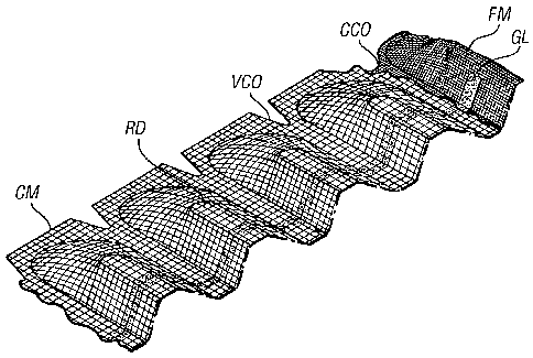
Referring now to Figures 12A to 12D, there is shown
a screen assembly which may be integral with a main
screen or be attachable to a main screen by gluing,
stapling, weaving or any other suitable attachment means.
Figure 4C shows a blank coarse screening material CM
comprising v-shaped slots VCO between each ridge RD to be
formed in the blank. A fine mesh FM is arranged
underneath the coarse Mesh M. C-shaped curves are formed
in the fine mesh FM between each ridge RD to be formed
CA 02381726 2002-02-11
WO 01/19492 PCT/GBOO/03571
- 20 -
therein. The coarse mesh CM is adhered and moulded with
the fine mesh FM. The coarse mesh CM is adhered to the
fine mesh FM with a strip of glue running substantially
perpendicular to the longitudinal axis of the ridges RD.
In this embodiment, the ridges are approximately 5cm
across at their base, having a flat top to the ridge of
approximately lcm wide. The ridge stands approximately
2.5cm from the valley. The V-shaped slots VCO are
approximately 2.5cm long and 2cm wide at the opening.
The present invention, therefore, provides in
certain, but not necessarily all embodiments, a screen
assembly for a vibratory separator, the screen assembly
having a ridge-valley series of undulating screening
material [screen(s), mesh(es) cloth(s), etc.] comprised
of a plurality of alternating ridges and valleys of
screening material, each of said ridges having two
spaced-apart ridge ends, a ridge top and a ridge bottom,
and each ridge end comprising a portion of screening
material that tapers down from its corresponding ridge's
ridge top to a level of screening material at its
corresponding ridge's ridge bottom. Such a method may
include one or some of the following, in any possible
combination: wherein said ridge ends are of a generally
bulbous shape; and/or wherein the screening material with
the ridge-valley series of undulating screening material
has an outer perimeter and wherein an outermost edge of
each ridge end at the level of the screening material at
the ridge bottom is within the perimeter of the screening
material.