Note: Descriptions are shown in the official language in which they were submitted.
CA 02381868 2002-04-16
Title
VACUUM RELIEF DEVICE
Scope of the Invention
[0001] This invention relates to a vacuum relief device and, more
particularly, to a
vacuum relief for relieving vacuum developed within a fluid containing
reservoir.
Background of the Invention
[0002] Arrangements are well known by which fluid is dispensed from fluid
containing reservoirs. For example, known hand soap dispensing systems provide
reservoirs containing liquid soap from which soap is to be dispensed. When the
reservoir
is enclosed and rigid so as to not be collapsible then, on dispensing liquid
soap from the
reservoir, a vacuum comes to be created in the reservoir. It is known to
provide one-way
valves which permit atmospheric air to enter the reservoir and permit the
vacuum in the
reservoir to be reduced. The one-way valves typically operate such that the
one-way
valve prevents air from entering the reservoir unless a vacuum is developed to
a certain
level below atmospheric pressure. To the extent that the vacuum increases
beyond this
certain level, then the valve will open permitting air to enter the reservoir
and thereby
prevent the vacuum from increasing further.
100031 The provision of vacuum relief valves is advantageous not only in
enclosed
reservoirs which are rigid but also with reservoirs that may not so readily
collapse as to
prevent the development of a vacuum within the reservoir on dispensing.
[0004] The present inventor has appreciated that reducing the ability of
vacuum
conditions to arise in any reservoir can be advantageous so as to facilitate
dispensing of
fluid from the reservoir, particularly so as to permit dispensing with a
minimal of effort
and with a pump which has minimal ability to overcome any vacuum pressure
differential
to atmospheric pressure.
100051 U.S. Patent 5,676,277 to Ophardt which issued October 14, 1997
discloses in
Figure 10 a known one-way valve structure in which a resilient flexible seal
member is
biased to close an air passageway such that on the development of vacuum
within a
_ .....___...~.~....~_ .,._.._...._..-
...._.....~.,..~~...~...~..~a_....._.._.... _.._.._,,.._..
CA 02381868 2002-04-16
reservoir, the seal member is deflected out of a position to close the air
passageway and
permits atmospheric air to enter the reservoir relieving the vacuum. Such
flexible seal
members suffer the disadvantage that they are subject to failure, do not
always provide a
suitable seal, and to be flexible must frequently be made from different
materials than the
remainder of the value structure. As well as insofar as a flexible seal member
is to be
maintained in contact with fluid from the reservoir, then difficulties may
arise in respect
of degradation of the flexible sealing member with time. As well, the flexible
sealing
member typically must experience some minimal level of vacuum in order to
operate and
such minimal level of vacuum can, in itself, at times present difficulty in
dispensing fluid
from the reservoir.
Summary of the Invention
[0006] To at least partially overcome these disadvantages of previously known
devices, the present invention provides a vacuum relief valve which comprises
an
enclosed chamber having an air inlet open to the atmosphere and a liquid inlet
in
communication with liquid in the reservoir and in which the liquid inlet opens
to the
chamber at a height below a height at which the air inlet opens to the
chamber.
[0007] An object of the present invention is to provide a sirnplified vacuum
relief
device, preferably for use with an enclosed reservoir in a fluid dispensing
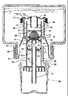
application.
[0008] Another object is to provide a vacuum relief'device witliout moving
parts.
[0009] Another object is to provide a vacuum relief device as part of a
disposable
plastic liquid pump.
[0010] Another object is to provide a liquid dispenser which is substantially
drip
proof.
[0011] Another object is to provide a simple dispenser in which a vacuum
relief
device for relieving vacuum in a reservoir also permits dispensing of liquid
therethrough
when the reservoir is pressurized.
[0012] Accordingly, in one aspect, the present invention provides a vacuum
relief
device adapted to permit atmospheric air to enter a liquid containing
reservoir to reduce
vacuum developed in the reservoir,
2
CA 02381868 2002-04-16
[0013] the device comprising:
[0014] an enclosed chamber having an air inlet and a liquid inlet,
100151 the air inlet in communication with air at atmospheric pressure,
[0016] the liquid inlet in communication with liquid in the reservoir,
[0017] the liquid inlet open to the chamber at a height which is below a
height at
which the air inlet is open to the chamber.
[0018] In another aspect, the present invention provides, in combination, an
enclosed,
liquid containing reservoir and a vacuum relief device,
[0019] the reservoir having a reservoir outlet from which liquid is to be
dispensed
and within which reservoir a vacuum below atmospheric pressure is developed on
dispensing liquid from the reservoir outlet,
[0020] the vacuum relief device is adapted to permit atmospheric air to enter
the
reservoir to reduce any vacuum developed in the reservoir,
[0021] the vacuum relief device comprising an enclosed chamber having an air
inlet
and a liquid inlet,
[0022] the liquid inlet open to the chamber at a height, which is below a
height at
which the air inlet is open to the chamber,
[0023] the air inlet in communication with air at atmospheric pressure such
that the
chamber is at atmospheric pressure,
[0024] the liquid inlet connected by via a liquid passageway with liquid in
the
reservoir,
[0025] the liquid inlet at a height below a height of liquid in the reservoir
such that
when pressure in the reservoir is atmospheric pressure, due to gravity the
liquid from the
reservoir fills the liquid passageway and, via the liquid passageway, fills
the chamber to a
height above the height of the liquid inlet and below the height of the air
inlet, and
wherein on dispensing liquid from the reservoir outlet increasing vacuum below
atmospheric in the reservoir, the height of liquid in the chamber decreases
until the height
of liquid is below the height of the liquid inlet and the liquid inlet is open
to air in the
chamber such that air in the chamber flows under gravity upward through the
liquid
passageway to the reservoir to decrease vacuum in the reservoir.
3
..._ . _
__.._..,.~.......,.,,~,.~w...,._...._........~,.._...,õ_.m..,..._,..____
_...._._._ _. _
CA 02381868 2002-04-16
[0026] In another aspect, the present invention provides, in coinbination, an
enclosed,
liquid containing reservoir and a vacuum relief device and a pump.
[0027] the reservoir having a reservoir outlet and within which reservoir a
vacuum
below atmospheric pressure is developed on drawing liquid from the reservoir
via the
outlet, and
[0028] the vacuum relief device is adapted to permit atmospheric air to enter
the
reservoir to reduce any vacuum developed in the reservoir,
[0029] the vacuum relief device comprising an enclosed chamber having an air
inlet
and a liquid inlet,
[0030] the liquid inlet open to the chamber at a height, which is below a
height at
which the air inlet is open to the chamber,
100311 the air inlet in communication with air at atmospheric pressure such
that the
chamber is at atmospheric pressure,
[0032] the liquid inlet connected by via a liquid passageway with the
reservoir outlet,
[0033] the liquid inlet at a height below a height of liquid in the reservoir
such that
when there is atmospheric pressure in the reservoir under gravity, the liquid
from the
reservoir fills the liquid passageway and, via the liquid passageway, fills
the chamber to a
height above the height of the liquid inlet and below the height of the air
inlet, and
wherein with increased vacuum below atmospheric in the reservoir the height of
liquid in
the chamber decreases until the height of liquid is below the height of the
liquid inlet and
the liquid inlet is open to air in the chamber such that air in the chamber
flows under
gravity upward through the liquid passageway to the reservoir to decrease
vacuum in the
reservoir,
[0034] a liquid outlet from the chamber open to the chamber at a height below
the
height of the liquid inlet,
[0035] a feed passageway connecting the liquid outlet with the pump, the pump
being
operable to draw liquid from the chamber via the liquid outlet and dispense it
via a
dispensing passageway to a dispensing outlet open to atmospheric pressure,
[0036] the dispensing passageway in extending fiom the pump to the dispensing
outlet rising to a height above the height of the liquid inlet such that
liquid in the
4
,~ .. _. _ __._ ,.~.....~w,~~~....~.~, ~.~...,.. _ ..... . _ _ ... .... _,~
.__----
CA 02381868 2002-04-16
dispensing passageway will, when the pump is not operating, assume a height in
the
dispensing passageway which is the same as the height in the chamber and below
the
height of the dispensing outlet to prevent flow of liquid due to gravity from
the chamber
out of the dispensing outlet.
[0037] In another aspect, the present invention provides a liquid dispenser
comprising:
[0038] a resilient, enclosed container enclosed but for having at one end of
the
container a neck open at a container outlet opening,
[0039] a cap having an end wall and a side wall extending from the end wall to
an
remote portion of the side wall,
[0040] a cap outlet opening through the side wall,
[0041] the cap received on the neck with the neck extending into the cap,
[0042] the remote portion of the cap about the neck engaging the neck to form
fluid
impermeable seal therewith,
[0043) a passageway defined between the neck and the side wall of the cap
outwardly
of the neck and inwardly of the side wall open to both the container outlet
opening and
the cap outlet opening,
100441 wherein when the container is in an inverted position with the neck
located
below the remainder of the container, the container outlet opening is at a
height which is
below a height of the cap outlet opening.
[0045] A vacuum relief valve in accordance with the present invention is
adapted for
use in a number of different embodiments of fluid reservoirs and dispensers.
It can be
formed to be compact so as to be a removable plastic compartment as, for
example,
adapted to fit inside the neck of' a bottle as, for example, part of and
inwardly from a
pump assembly forming a plug for a bottle.
[0046] The vacuum relief valve may be used not only to relieve vacuum pressure
in a
reservoir but also for dispensing liquid therethrough, either due to pressure
in the
reservoir or a pump drawing liquid out from a chamber in the vacuum relief
valve.
[0047] The vacuum relief valve may be used to provide a dispenser which does
not
drip by having dispensed from a chamber in. the vacuum relief valve through a
dispensing
CA 02381868 2002-04-16
tube which rises to a height above the liquid level in the chamber in the
vacuum relief
valve.
[0048] The vacuum relief valve may be configured to be closed to prevent
liquid flow
from a reservoir and to be opened for operation.
Brief Description of the Drawings
[0049] Further aspects and advantages of the invention will become apparent
from
the following description taken together with the accompanying drawings in
which:
[0050] Figure 1 is a schematic view of the soap dispenser incorporating a
vacuum
relief device in accordance with a first embodiment of the present invention
illustrating a
condition in which atmospheric air is passing into a reservoir;
[0051] Figure 2 is a schematic side view of the soap dispenser of Figure 1,
however,
illustrating a condition in which liquid is at a position to flow from the
vacuum relief
device;
[0052] Figure 3 is a cross-sectional view through the vacuum relief device of
Figure
1 along section lines 3-3';
[0053] Figure 4 is a schematic cross-sectional view of a fluid dispenser
including a
vacuum relief device in accordance with a second embodiment of the invention
under
conditions in which atmospheric air is passing into a reservoir;
[0054] Figure 5 is a cross-sectional view through the vacuum relief device of
Figure
4 along section lines 5-5';
[0055] Figure 6 is a schematic pictorial and partially sectional view of a
third
embodiment of a vacuum relief value in accordance with present invention;
[0056] Figure 7 is a cross-sectional side view of a liquid dispenser having a
pump
assembly attached to a reservoir and incorporating a vacuum relief device in
accordance
with a fourth embodiment of the present invention;
[0057] Figure 8 is a cross-sectional side view through Figure 7 normal to the
cross-
section through Figure 7;
[0058] Figure 9 is a schematic cross-sectional view of a fluid dispenser
including a
vacuum relief device in accordance with a fifth embodiment of the present
invention;
6
..~...~.., ...~...._.__ _. _ _...~.,._...._..-.~~...~.~.._.
CA 02381868 2002-04-16
[0059] Figure 10 is a pictorial view of a fluid dispenser in accordance with a
sixth
embodiment of the present invention;
[0060] Figure 11 is an exploded view of components of the dispenser of Figure
10;
[0061] Figure 12 is a vertical cross-sectional view through the dispenser of
Figure 10;
[0062] Figure 13 is a vertical cross-section through a dispenser in accordance
with a
seventh embodiment of the present invention similar to the embodiment shown in
Figure
12 and in an open position;
[0063] Figure 14 is a vertical cross-sectional of the dispenser of Figure 13
in a closed
position.
[0064] Figure 15 is an exploded side view of a liquid dispenser in accordance
with an
eighth embodiment of the present invention;
[0065] Figure 16 is an end view of the bottle shown in Figure 15;
[0066] Figure 17 is a cross-sectional erid view of the cap shown in Figure 15
along
section line A-A';
[0067] Figure 18 is a side view of the liquid dispenser of Figure 15 in a
closed
position;
[0068] Figure 19 is a side view of the liquid dispenser of Figure 15 in an
open
position;
[0069] Figure 20 is a schematic cross-sectional view for a fluid dispenser
substantially the same as that shown in Figure 4; and
[0070] Figure 21 is a cross-sectional view through Figure 4 along section line
B-B'.
Detailed Description of the Drawings
[0071] Reference is made first to Figures 1, 2 and 3 which schematically show,
without regard to scale, a soap dispensing apparatus 10 incorporating a vacuum
relief
device 12 in accordance with the present invention. A reservoir 18 is shown
schematically as comprising an enclosed non-collapsible reservoir having an
outlet 22 in
communication with a pump 24. I'he pump 24 is operative to dispense fluid 26
from the
reservoir. The reservoir is shown to have fluid 26 in the lower portion of the
reservoir
7
CA 02381868 2002-04-16
with an upper surface 27 separating the fluid 26 from a pocket of air 28
within an upper
portion of reservoir above the fluid 26.
[0072] The vacuum relief device 12 is illustrated as having a vessel including
a base
30 and a cap 32 forming an enclosed chamber 33. As best seen in Figure 3, the
base 30 is
cylindrical having a bottom wall. 34 and a cylindrical upstanding side wall
36. The cap
32 is shown as having a cylindrical lip portion 31 adapted to secure the cap
32 to the
upper edge of the cylindrical side wa1136 of the base forming a fluid tight
seal therewith.
A cylindrical air tube 38 extends upwardly from the base 30 to an air inlet
40. A liquid
tube 42 extends downwardly from the cap 32 to a liquid inlet 44. As seen in
both Figures
1 and 2, the vacuum relief device 12 is intended to be used in a vertical
orientation as
shown in the figures with the cap 32 at an upper position and the cylindrical
side wall 36
oriented to extend vertically upwardly. As shown, the air inlet 40 opens into
the chamber
33 at a height which is above a height at which the liquid inlet 44 opens into
the chamber
33. The vertical distance between the air inlet 40 and the liquid inlet 44 is
illustrated as
being "h".
[0073] The vacuum relief device 12 is to be coupled to the reservoir 18 in a
manner
that the liquid inlet 44 is in communication via a liquid passageway passing
through
liquid tube 42 with the fluid 26 in the reservoir. For simplicity of
illustration, the
reservoir 18 is shown to have an open bottom which is in a sealed relation
with the cap
32. The air inlet 40 is in commimication via the air tube 38 with atmospheric
air at
atmospheric pressure.
[0074] Referring to Figure 1, in the condition shown, the pump 24 has
dispensed
liquid from the reservoir such that the pressure in the reservoir 18 has been
drawn below
atmospheric pressure thus creating a vacuum in the reservoir. As a result of
this vacuum,
liquid 26 within the chamber 33 has been drawn upwardly from the chamber 33
through
the liquid tube 42 into the reservoir 18. Figure 1 illustrates a condition in
which the
vacuum which exists in the reservoir 18 is sufficient that the level. of the
liquid 26 in the
chamber 33 has been drawn down to the height of the liquid inlet 44 and thus
air which is
within the chamber 33 above the liquid 26 in the chamber 33 comes to be at and
below
the height of the liquid inlet 44 and, thus, has entered the liquid tube 42
via the liquid
8
CA 02381868 2002-04-16
inlet 44 and the air is moving as shown by air bubbles 29 under gravity
upwardly through
the fluid 26 in liquid tube 44 and reservoir 18 to come to form part of the
air 28 in the top
of the reservoir 18.
[0075] Since the air tube 38 is open to atmospheric air, atmospheric air is
free to enter
the chamber 33 via the air tube 38 and, hence, be available to enter the
liquid tube 42.
[0076] Reference is made to Figure 2 which is identical to Figure 1, however,
shows
a condition in which the level of liquid 26 in the chamber 33 is just
marginally above the
height of the air inlet 40 and liquid 26 is flowing from the chamber 33 out
the air tube 38
as shown by liquid droplets 27.
[0077] Figure 2 illustrates a condition which is typically not desired to be
achieved
under normal operation of the fluid dispensing system of Figures 1 to 3. That
is, the
vacuum relief device 12 is preferably to be used as in the embodiment of
Figures 1 to 3 in
a manner to permit air to pass into the reservoir 18 as illustrated in Figure
3 and it is
desired to avoid a condition as shown in Figure 2 in which fluid 26 will flow
out of the
air tube 38.
[0078] In the first embodiment of Figures 1 to 3, the air inlet 40 is desired
to be at a
height above the height to which the level of the liquid may, in normal
operation, rise in
the chamber 33. It is, therefore, a simple matter to determine this height and
provide a
height to the air inlet 40 which ensures that under reasonable operating
conditions that the
liquid will not be able to flow from the chaniber 33 out the air tube 38.
[0079] Provided the fluid 26 fills the chamber 33 to or above the level of the
liquid
inlet 44, then air from the chamber 33 is prevented from accessing the liquid
inlet 44 and
cannot pass through the liquid tube 42 into the reservoir. The ability of
liquid 26 to be
dispensed out of the reservoir 18 by the pump 26 may possibly be limited to
some extent
to the degree to which a vacuum may exist in the reservoir. For vacuum to
exist in the
reservoir, there must be an expandable fluid in the reservoir such as air 28
or other gases
above the liquid 26. At any time, the level of the liquid in the chamber 33
will be factor
which will determine the amount of additional vacuum which must be created
within the
reservoir 18 in order for the level of liquid in the chamber 33 to drop
sufficiently that the
9
CA 02381868 2002-04-16
level of liquid in the chamber 33 becomes below the liquid inlet 44 and air
may pass from
the chamber 33 up through the liquid tube 42 into the reservoir 18 to reduce
the vacuum.
[0080] As seen in Figures 1 and 2, the liquid 26 forms a continuous column of
liquid
through the liquid in the chamber 33, through the liquid in the liquid tube 42
and through
the liquid in the reservoir 18. Air which may enter liquid inlet 44 will flow
upwardly to
the top of the reservoir 18 without becoming trapped as in a trap like portion
of the liquid
passageway. Similarly, liquid 26 will flow downwardly from the reservoir 18
through
the liquid tube 42 to the chamber 33 to effectively self prime the system,
unless the
vacuum in the reservoir 18 is too great.
100811 Reference is made to Figures 4 and 5 which show a second embodiment of
a
vacuum relief device 10 in accordance with the present invention illustrated
in a similar
schematic arrangement as the first embodiment of Figures 1 to 3. The second
embodiment has an equivalent to every element in the first embodiment,
however, is
arranged such that the liquid tube 42 is coaxial with the cap 32 and a
cylindrical holding
tube 46 extends upwardly from the base 30 concentrically about the liquid tube
42. An
air aperture 41 is provided in the base 30 opening into an annular air
passageway 43
between the cylindrical side wall 36 and the holding tube 46. Conceptually, as
compared
to Figure 1, the effective location and height of the air inlet 40 is at the
upper open end of
the holding tube 46 which is, of course, at a height above the liquid inlet
44. Figure 4
shows a condition in which the vacuum in the reservoir 18 is sufficient that
the liquid in
the holding tube 46 is drawn downwardly to the level of the liquid inlet 44
and air, as in
air bubbles 29, may flow upwardly through the liquid tube 42 into the
reservoir 18 to
relieve the vacuum.
[0082] In both the embodiments illustrated in Figures 1 to 3 and in Figures 4
and 5,
the vacuum relief device is constructed of two parts, preferably of plastic by
injection
moulding with a cap 32 adapted to be secured in a sealing relation to be the
base 30. The
vacuum relief device 12 is adapted to be received within an opening into the
reservoir 18
or otherwise provided to have, on one hand, communication with liquid in the
reservoir
and, on the other hand, communication with atmospheric air.
CA 02381868 2008-12-22
[0083] Figure 6 illustrates another simple embodiment of a vacuum relief
device 12
in accordance with the present invention. In this embodiment, the device 12
comprises a
cylindrical vessel with closed flat end walls 50 and 52 and a cylindrical side
wall 54
which is adapted to be received in a cylindrical opening 56 in the side wall
57 of a
reservoir 18 as shown, preferably with a central axis 58 through the
cylindrical vessel
disposed generally horizontally. An inner end wal150 of the vessel has the
liquid inlet 44
and the outer end wall 52 of the vessel has the air inlet 40. The vessel is to
be secured to
the reservoir 18 such that the air inlet 40 is disposed at a height above the
liquid inlet 44.
It is to be appreciated that this height relationship may be accommodated by
orienting the
device 10 at orientations other than with the axis 58 horizontal as shown.
Figure 6
illustrates a cross-sectional through a vertical plane including the central
axis 58 and in
which plane for convenience the centers of each of the air inlet 40 and liquid
inlet 44 lie.
[0084] Reference is made to Figures 7 and 8 which show a liquid dispenser
having a
pump assembly attached to a reservoir and incorporating the vacuum relief
device in
accordance with the present invention. The pump assembly of Figures 7 and 8
has a
configuration substantially as disclosed in Figure 10 of the applicant's U.S.
Patent
5,676,277 to Ophardt, issued October 14, 1997 but including a vacuum relief
valve
device 12 in accordance with the present invention mounted coaxially with the
pump
assembly inwardly of the pump assembly.
[0085] The reservoir 18 is a rigid bottle with a threaded neck 62. The pump
assembly
has a piston chamber-forming body 66 defining a chamber 68 therein in which a
piston
forming element or piston 70 is slidably disposed for reciprocal movement to
dispense
fluid from the reservoir. Openings 72 in the end wall 67 of the chamber 68 is
in
communication with the fluid in the reservoir 18 via a radially extending
passageway 74
as best seen in Figure S. A one-way valve 76 across the opening 72 permits
fluid flow
outwardly from the passageway 74 into the chamber 68 but prevents fluid flow
inwardly.
[0086] The piston chamber-forming body 66 has a cylindrical inner tube 78
defining
the chamber 68 therein. An outer tubular member 80 is provided radially
outwardly of
the inner tube 78 joined by a radially extending shoulder 82 to the inner tube
78. The
outer tubular member 80 extends outwardly so as to define an annular air space
84
11
CA 02381868 2002-04-16
between the outer tubular member 80 and the inner tube 78. The outer tubular
member
80 carries threaded flange 86 thereon extending upwardly and outwardly
therefrom to
define an annular thread space 87 therebetween. The threaded flange 86 engages
the
threaded neck 62 of the reservoir 18 to form a fluid impermeable seal
therewith.
[0087] The vacuum relief device 12 in Figures 7 and 8 has a configuration
substantially identical to that in Figures 4 and 5 with coaxial upstanding
side wall 36 and
upstanding holding tube 46. A cap 32 sealably secured to the upper end of the
side wall
36 carries the liquid tube 42 coaxially within the holding tube 46. The upper
end of the
liquid tube 42 is in communication with fluid in the reservoir. An annular air
chamber 43
is defined between the wall 36 and the holding tube 46. Air apertures 41
provide
communication between the annular air chamber 43 and the annular air space 84
which is
open to atmospheric air. The apertures 41 extend through the shoulder 82
joining the
inner tube 78 to the outer tubular member 80. The shoulder 82 may also be
considered to
join the holding tube 46 to the cylindrical wall 36. The cylindrical wall 36
may be
considered an inward extension of the outer tubular member 80. The holding
tube 46
may be considered an inward extension of the inner tube 78.
[0088] As best seen in Figure 8, the passageway 74 extends radially outwardly
through the holding tube 46 and the cylindrical wal136 such that the
passageway 74 is in
open communication with fluid in the reservoir at diametrically opposed
positions at both
a first open end through one side of the wail 36 and at a second open end
through the
other side of the wall 36. Fluid from the reservoir is in communication via
passageway
74 to the opening 72 to the piston chamber 68. The passageway 74 is defined
between a
top wall 90 and side walls 91 and 92 with a bottom formed by the shoulder 82
and the
inner end 67 of the chamber 68. The top wall 90 forms the floor of the chamber
33
defined within the holding tube 46.
[0089] The piston chamber-forming body 66 is preferably injection moulded as a
unitary element including the vacuum relief device other than its cap 32 which
is
preferably formed as a separate injection moulded element. The one-way valve
76 and
the piston forming element 70 are also separate elements.
12
CA 02381868 2002-04-16
[0090] The one-way valve 76 has a shouldered button 75 which is secured in a
snap-
fit inside a central opening in the end wa1167 of the chamber 68, a flexible
annular rim 77
is carried by the button and extends radially outwardly to the side wall of
the inner tube
78. When the pressure in passageway 74 is greater than that in chamber 68, the
rim 77 is
deflected away from the walls of the inner tube 78 and fluid may flow from
passageway
74 through exit openings 72 in the end wall 76 and past the rim 77 into the
chamber 68.
Fluid flow in the opposite direction is blocked by rim 77.
[0091] The piston-forming element or piston 70 is a preferably unitary element
formed of plastic. The piston 70 has a hollow stem 90. Two circular discs 91
and 92 are
located on the stem spaced from each other. An inner disc 91 resiliently
engages the side
wall of the chamber 68 to permit fluid flow outwardly therepast but to
restrict fluid flow
inwardly. An outer disc 92 engages the side walls of the chamber 68 to prevent
fluid
flow outwardly therepast.
[0092] The piston stem 90 has a hollow passageway 93 extending along the axis
of
the piston 70 from a blind inner end to an outlet 94 at an outer end. Inlets
95 to the
passageway 93 are provided between the inner disc 91 and outer disc 92. By
reciprocal
movement of the piston 70 in the chamber 68, fluid is drawn from passageway 74
through exit openings 72 past the one-way valve 76 and via the inlets 95
through the
passageway 93 to exit the outlet 94.
[0093] As fluid is pumped from the reservoir 18, a vacuum may be developed in
the
reservoir and the pressure relief valve 12 may permit air to enter the
reservoir 18 in the
same manner as described with reference to Figures 4 and 5.
[0094] The two air apertures 41 shown in Figure 7 are intended to be
relatively small
circular openings. Figure 7 shows a removable closure cap 88 adapted to be
secured to
the outer tubular member 80 in a snap-fit relation and which is removable to
operate the
pump. The removable closure cap 88 is shown to be provided with a pendant arm
96
which is secured to the right hand side of the closure cap and extend inwardly
to present
an inner plug end 97 to sealably engages within an air aperture 41 to sealably
close the
same. On removal of the closure cap 88, the inner plug end 97 of the pendant
arm would
be removed from sealing engagement in the air aperture 41. The pendant arm may
be
13
.o......~._.,,,.~...-õ . , _ _._._. _~-_...~. ~.._ ._ . . _ _._.._..~ ..._~._.
CA 02381868 2008-12-22
hingedly mounted to the closure cap 88 so as to be deflectable to pass
outwardly about
the piston forming element 70. The inner plug end 97 may be cammed and guided
into
the air aperture 41 on applying the closure cap 88 to the outer tubular member
80 as by
engagement with the tube 78. While for ease of illustration, only one pendant
arm 96 is
shown, one such an arm preferably may be provided to close each air aperture
41.
[0095] Plugs to close the air apertures 41 could alternatively be a removable
element
independent of the closure cap 88. As well, the shoulder 82 joining the inner
tube 78 to
the outer tubular member 80 and the cylindrical wall 36 could be reconfigured
and
relocated to be at a location outwardly from where it is shown in Figure 7
such as, for
example, to be proximate the inner end 98 of the removable closure cap 88 such
that the
inner end 98 of the removable closure cap could serve a purpose of sealing the
air
apertures 41 without the need for separate pendant arms 96.
[0096] The embodiment of Figures 7 and 8 show a pressure relief device 12
inward
of the pump assembly. The pump assembly includes the one-way valve 76 and a
piston
70 with two discs 91 and 92 as disclosed in Figure 9 of U.S. Patent 5,975,360
to Ophardt
issued November 2, 1999.
[0097] It is to be appreciated that the pump assembly could be substituted
with a
pump assembly which avoids a separate one-way valve and has three discs which
could
be used as disclosed, for example, in Figure 11 of U.S. Patent 5,975,360.
Other
pump assemblies may be used with the pressure relief device 12 similarly
mounted
inwardly.
[0098] Figures 7 and 8 illustrate an embodiment in which a removable
dispensing
plug is provided in the mouth of the reservoir, the dispensing plug
comprising, in
combination, a vacuum relief device and pump assembly with the vacuum relief
device
effectively coaxially disposed inwardly of the pump assembly. This is
advantageous for
reservoirs with relatively small diameter mouths. With larger mouths, the
dispensing
plug may have the pump assembly and vacuum relief device mounted side by side.
In
either case, as seen, the piston chamber-forming element 66 may comprise a
unitary
element formed by injection moulding and including (a) an element to couple to
the
14
CA 02381868 2002-04-16
mouth of the reservoir, namely, outer tubular member 80, (b) the inner tube 78
to receive
the piston 70, (c) the side wal136, imd (d) the holding tube 46.
[00991 Reference is made to Figure 9 which schematically shows an embodiment
in
accordance with the present invention very similar to that shown in Figures l
to 3,
however, with the pump 24 disposed so as to draw fluid from the chamber 33
rather than
from the reservoir 18. In this regard, the outlet 22 for the pump 24 is shown
as being
provided to extend from the base 30 at a height below the liquid inlet 44.
Fluid from the
pump 24 flows via an outlet tube 100 to an outlet 102.
101001 Figure 9 shows the reservoir 18, the vacuum relief device 12 and the
outlet
102 at preferred relative heights in accordance with the present invention.
Figure 9
shows a condition in which the pump is not operating and the level of the
liquid 26
assumes in the outlet tube 100 as being at a height which is effectively the
same as the
height of the level of the liquid 26 in the chamber 33. The height of the
level of the
liquid 26 in the chamber 33 and, therefore, in the outlet tube 100, is
selected to be below
the height of the outlet 102. With this arrangement, liquid does not have a
tendency to
drip out the outlet 102 even though liquid in the reservoir 18 is at a height
above the
outlet 102. This configuration is particularly advantageous for use with
relatively low
viscosity liquids such as alcohol solutions as are used in disinfecting and
hand cleaning in
hospitals. Dispensers for such alcohol solutions frequently suffer the
disadvantage that
the alcohol will drip out of the outlet and, while it has previously been
known in the past
to provide the outlet for the alcohol at a height above the level of alcohol
in the reservoir,
this is, to some extent, impractical and increases the pressure with which the
alcohol
needs to be pumped by the pump to be moved to a height above the height of the
alcohol
in the reservoir. In accordance with the embodiment illustrated in Figure 9,
the pressure
relief device 12 can be of relatively small dimension and, therefore, the
outlet 102 needs
only be raised a relatively small amount to place the outlet 102 at a height
above the level
of the liquid 26 in the chamber 33. For example, the height of a typical
reservoir is
generally in the range of six to eighteen inches whereas the height of the
vacuum relief
device 12 may be only in the range of about one inch or less.
CA 02381868 2008-12-22
[0101] Figure 9 schematically illustrates the pump 24. This pump may
preferably
comprise a pump as disclosed in the applicant's U.S. Patent 5,836,482, issued
November 17, 1998 to Ophardt and U.S. Patent 6,343,724, issued February 5,
2002 to
Ophardt. Fluid dispensers with such pumps preferably have configurations to
reduce the
frictional forces arising in fluid flow which need to be overcome by the pump
so as to
increase the useful life of batteries and, therefore, minimize the size and
quantities of
batteries used. The embodiment illustrated in Figure 9 has the advantage that
a one-way
valve is not required to prevent dripping from the outlet and, thus, during
pumping, there
is a minimum of resistance to fluid flow since fluid may flow directly from
the reservoir
to the chamber 33, from the chamber 33 to the pump 24 and, hence, from the
pump 24
via the outlet tube 100 to the outlet 102. The relative height of the outlet
102 above the
height of the liquid inlet 44 ensures there will be no dripping. Thus, the
vacuum relief
device 12 as used in the context of Figure 9 not only serves a purpose of
providing a
convenient structure to permit air to pass upwardly into the reservoir 18 to
relieve any
vacuum developed therein, but also provides an arrangement by which a
mechanical
valve is not required to prevent dripping and in which the height at which the
outlet must
be located is below the height of the liquid in the reservoir 18 and merely
needs to be
above the height of the liquid in the chamber 33.
[0102] While the schematic embodiment illustrated in Figure 9 shows the pump
as
disposed below the vacuum relief device 12, it is to be appreciated that the
pump could
readily be disposed to one side, further reducing the length of the outlet
tube.
[0103] Figures 10, 11 and 12 show an arrangement as taught in Figure 9
utilizing as
the pump a pump in U.S. Patent 6,343,724. The dispenser generally indicated
110
includes a non-collapsible fluid container 111 with outlet member 114
providing an exit
passageway 115 for exit of fluid from the container 111.
[0104] The pump/valve assembly 112 is best shown as comprising several
separate
elements, namely, a feed tube 122, a pump 120 and an outlet tube 100. The pump
120
16
CA 02381868 2002-04-16
includes a pump casing 156, a drive impeller 152, a driven impeller 153, a
casing plug
158 and a drive shaft 159.
[0105] The cylindrical feed tube 122 is adapted to be received in sealing
engagement
in the cylindrical exit passageway 115 of the outlet member 114. The feed tube
122
incorporates a vacuum relief device in accordance with the present invention
and the
cylindrical feed tube 122 is best seen in cross-section in Figure 12 to have a
configuration
similar to that in Figure 4, however, with the notable exception that the
outlet 22 is
provided as a cylindrical outer extension of' the holding tube 46. 'The cap 32
is provided
to be located in a snap-fit internally within the cylindrical side walls 36.
The outlet 22
leads to the pump 120 from which fluid is pumped by rotation of the impellers
152 and
153. The outlet tube 100 is a separate element frictionally engaged on a spout-
like outlet
118 on the pump casing 156. The outlet tube 100 has a generally S-shaped
configuration
and extends upwardly so as to provide its outlet 102 at a height above the
height of the
liquid inlet 44. As seen in Figure 12, the fluid in the outlet tube 100
assumes the height
of the fluid in the chamber 33 which is below the height of the outlet 102 so
that there is
no dripping out of the outlet 102.
[0106] The embodiment of Figure 12 is particularly advantageous for liquids of
low
viscosity such as alcohol and water based solutions in which dripping can be
an increased
problem. The embodiment of Figure 12 does not require a mechanical one-way
valve to
prevent dripping and can have fluid dispensed though it with minimal effort.
The
dispenser illustrated is easily primed and will be self-priming since the gear
pump is a
pump which typically, when it is not operating, permits low viscosity fluids
to slowly
pass therethrough. As disclosed in U.S. Patent 6,343,724, the drive shaft 159
is adapted
to be coupled to a motor, preferably a battery operated motor, maintained in a
dispenser
housing. The entirety of the pump assembly shown in Figure 12 can be made of
plastic
and be disposable.
[0107] Reference is made to Figures 13 and 14 which show a modified form of
the
dispenser of Figure 12. The embodiment of Figures 13 and 14 is identical to
that of
Figure 12 with the exception that the pressure relief device is made from two
different
parts, namely, an inner element 103 and an outer element 104. The inner
element 103 is
17
CA 02381868 2002-04-16
a unitary element comprising the cap 32 merged with an outer cylindrical
wa1136a ending
at an outwardly extending cylindrical opening. The outer element 104 includes
the
holding tube 46, the exit tube 22 and the base 30 merged with an inner
cylindrical wall
36b ending at an inwardly extenditig cylindrical opening. An air aperture 41
is provided
in an outermost portion of the inner cylindrical wall 36b. The outer element
104 is
coaxially received in the inner element 103 for relative axial sliding between
the open
position of Figure 13 to the closed position of Figure 14. The inner and outer
cylindrical
walls 36b and 36a engage each other to form a fluid impermeable seal
therebetween.
[0108] The outer element 104 includes within the holding tube 46 a disc-like
closure
member 105 carrying an inwardly extending central plug 106 to engage the
liquid inlet 44
and close the same. Radially outwardly of the central plug 106, the closure
member 105
has an opening 107 therethrough for free passage of the fluid 26.
[0109] In open position as shown in Figure 13, the pressure relief valve 12
functions
identically to the manner in Figure 12. In the closed position of Figure 14,
the plug 106
engages the liquid inlet 44 and prevents flow of fluid from the reservoir 18
via liquid tube
42. As well, in the closed position of Figure 14, the air aperture 41 is
closed by being
covered by the outer cylindrical wall 36a. Various mechanisms may be provided
to
releasably lock the outer element 104 in the locked and unlocked positions. In
the axial
sliding of the inner element 103 and outer element 104, the plug 106 acts like
a valve
movable to open and close a liquid passageway through the liquid tube 42.
Similarly, the
outer cylindrical wall 36a acts like a valve inovable to open and close an air
passageway
through the air aperture 41.
[0110] Figures 13 and 14 show the inner element 103 carrying on its outer
cylindrical
wal136a a lip structure 107 to engage the mouth of the container's outlet
member 114 in
a snap friction fit relation against easy removal.
[0111] The outer element 104 is also shown to carry on its inner cylindrical
wall 36b
a lesser lip structure 108 to engage the inner element 103 and hold the outer
element 104
in a closed position until the lip structure 108 may be released to move the
outer element
104 to the open position. Various other catch assemblies, thread systems and
fragible
closure mechanisms may be utilized.
18
CA 02381868 2002-04-16
101121 The container 111 filled with liquid with its outlet member 114
directed
upwardly may have a pump assembly as shown in Figure 14 applied thereto in a
closed
position to seal the fluid in the container. For use, the container niay be
inverted and the
outer element 104 moved axially outwardly to the open position of' Figure 13.
Preferably,
a dispenser housing to receive the container 111 with the pump assembly
attached may
require, as a matter of coupling of the container and pump assembly to the
housing, that
the outer element 104 necessarily be moved to the open position of Figure 13.
[0113] Each of the inner element 103 and outer element 104 may be an integral
element formed from plastic by injection moulding.
[0114] Reference is made to Figures 15 to 19 which shows another embodiment of
a
fluid dispenser in accordance with the present invention.
[0115] Figure 15 shows the dispenser 200 including a bottle 202 and a cap 204.
[0116] The bottle 202 has a body 206 which is rectangular in cross-section as
seen in
Figure 16 and a neck 208 which is generally circular in cross-section about a
longitudinal
axis 210. The neck 208 includes a threaded inner neck portion 212 carrying
external
threads 214. The inner portion 212 merges into a liquid tube 42 of reduced
diameter.
[0117] The cap 204 has a base 34 with a cylindrical side wall 36 carrying
internal
threads 216 adapted to engage the threaded neck portion 212 in a fluid sealed
engagement. An air tube 38 extends radially from the side wa1136. A central
plug 106 is
carried on the base 34 upstanding therefrom. In an assembled closed position
as seen in
Figure 18, the cap 204 is threaded onto the neck 208 of the bottle 202 to an
extent that the
plug 106 engages the end of the liquid tube 42 and seals the liquid tube 42 so
as to
prevent flow of fluid into or out of the bottle 202.
[0118] From the position of Figure 18, by rotation of the cap 204 180
relative the
bottle 202, the cap 204 assumes an open position in which the neck of the
bottle and the
cap form a vacuum relief device with the liquid tube 42 having a liquid inlet
44 at a
height below the height of an air inlet 40 at the inner end of the air tube
38. With the
bottle in the inverted position with its neck down as shown, cap and neck will
function
not only as a vacuum relief valve but also as a dispensing outlet. In this
regard, the bottle
202 is preferably a resilient plastic bottle as formed by blow moulded which
has an
19
_ _._. . _ . . ..._.,~.,.,..,,...~...A~.._,..~,...~..~,~...-.......~ .. _ _
___ _-__ ___.~
CA 02381868 2002-04-16
inherent bias to assume an inherent shape having an inherent internal volume.
The bottle
may be compressed as by having its side surfaces moved inwardly so as to be
deformed
to shapes different than the inherent shape and having volumes less than the
inherent
volume but which, on removal of compressive fences, will assume its original
inherent
shape.
[0119] With the bottle in the position of Figure 18 on compressing the bottle,
as by
manually squeezing the bottle, fluid 26 in the bottle is pressurized and
forced to flow out
of the liquid tube 42 into the chamber 33 in the cap 202 and, hence, out the
air tube 38.
On ceasing to compress the bottle, the bottle due to its resiliency, will
attempt to resume
its normal shape and, in so doing, will create a vacuum in the bottle, in
which case the
liquid tube 42 and air tube 38 in. the cavity 33 will act like a vacuum relief
valve in the
same manner as described with the embodinlent of Figures 1 to 6.
[0120] The bottle and cap may be rnounted to a wall by a simple mounting
mechanism and fluid dispensed merely by a user pushing on the side of the
bottle into the
wall. The bottle and cap could be mounted within an enclosing housing with
some
mechanism to apply compressive forces to the side of the bottle, as in
response to
movement of a manual lever or an electrically operated pusher element.
[0121] The bottle and cap niay be adapted to be stored ready for use in the
open
position inverted as shown in Figure 19 and an extension of the base 34 of the
cap 204 is
shown in dotted lines as 220 to provide an enlarged platform to support the
bottle and cap
inverted on a flat surface such as a table. In use, the bottle and cap may be
kept in an
inverted open position and liquid will not drip out since the liquid in the
chamber 33 will
assume a level below the liquid inlet 42 and the air inlet 40. Alternatively,
a hook may
be provided, as shown in dashed lines as 222 in Figure 9, to hang the bottle
and cap
inverted in a shower. The bottle and cap need be closed merely for shipping
and storage
before use.
[0122] Reference is made to Figures 19 and 20 which shows a device identical
to that
in Figures 4 and 5 but for firstly, the location of the air aperture 41 in the
side wall 36,
secondly, providing the base 34 to be at different heights under the holding
tube 46 than
under the annular air passageway 43 and, thirdly, the liquid tube 42 carries
on its outer
CA 02381868 2002-04-16
surface a plurality of spaced radially outwardly extending annular rings 39
which extend
to the tube 46. Each ring has an opening 230 adjacent its outer edge to permit
flow
between the tube 42 and the tube 46.
[0123] The openings 230 ori alternate rings are disposed 180 from each other
to
provide an extended length flow path for fluid flow through the passageway
between
liquid tube 42 and holding tube 46.
[0124] These annular rings are not necessary. They are intended to show one
form of
a flow restriction device which may optionally be provided to restrict flow of
liquid but
not restrict flow of air therethrough. The purpose of the annular rings is to
provide
reduced surface area for flow between the liquid tube 42 and the holding tube
46 as
through relatively small spaces or openings with the spaces or openings
selected to not
restrict the flow of air but to provide increased resistance to flow of
liquids, particularly
viscous soaps and the like, therethrough. This is perceived to be an advantage
in
dispensers where liquid flow out of air inlet 40 is not desired, should a
condition arise in
which liquid is attempting to pass from inside the tube 42 through the inside
of tube 40
and out of the air inlet 40 or air opening 41. Having increased resistance to
fluid flow
may be of assistance in reducing flow leakage out of the air apertures 41
under certain
conditions.
[0125] While the invention has been described with reference to preferred
embodiments, many modifications and variations will now occur to persons
skilled in the
art. For a definition of the invention, reference is made to the appended
claims.
21