Note: Descriptions are shown in the official language in which they were submitted.
°
CA 02382046 2002-02-13
' ?~~ ~ / ~ - al oct;~~
INDIVIDUAL AUTONOMOUS HEATER
Specification
Field of the Invention
The invention relates to an autonomous heating device in the form of an
individual
package comprising, in particular, exothermic material as a source, which is
placed between
two layers: an outer, contacting with air and the source of heat, and a
flexible heat
distributing layer that is placed between the source of heat and the object
being heated. This
heating device may be used, for example, as a medical heating pad, to heat
food products and
beverages, etc.
' Background of the Invention
In recent years a great deal of attention has been devoted to developing and
using heat .
generating materials and articles based thereon. For example, phase change
materials,
capable of storing and generating heat, have found wide use in building
materials, materials
for road surfaces, containers for beverages and food products, in medical
heating pads and in
textile articles, for example, in clothes.
For example, seat pads were proposed [LTSA patent 4995126, 1991, IPCS A47C
21/04]. Powders of an oxidized metal and a water-containing material, which
are arranged
in the form of an inner layer between two outer shells, one of which ensuring
the access of
air, are used in those pads as a disposable exothermic material, i.e. a
material capable of
generating heat.
An appliance for heating food is also known in which there is an exothermic
material
comprising powder of an easily corroded Mg-Fe alloy, which is activated by
water, and other
additives [USA patent 5117809, 1992, IPC' F24J 1/00]. Of importance during the
development of this appliance are the requirements stipulated in respect of
the shell in which
the heat-generating material is disposed.
Quite often, problems of heating devices are the nonuniform heating over the
plane of
the heating device and the possibility of local overheating that is due to the
high heat-
generating capability of the source of heat and the low heat conductivity of
the object being
n
CA 02382046 2002-02-13
7
heated, in particular, a human body. For example, when a medical heating pad
is used in
which the source of heat is concentrated in a small volume, high heating, even
a burn, may
occur on one portion of the part of the body being heated, while other
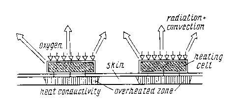
portions that require
heating remain unheated. A diagram of the heat flows in pads of known
constructions is
shown in Fig. 1.
One more problem may be the requirement that the heating device should be
sufficiently flexible so that maximum contact with the object being heated is
achieved. In
the case of medical heating pads, for example, it is desirable that it have
maximum contact
with the human body.
These problems may be solved by different methods. For example, one method
could be distribution of the source of heat over a wider surface of the
heating device.
However, such a method cannot always be used, for example, in the case where
it is not
possible to distribute or place the source of heat over a large surface or
where such placement
results in a substantial loss in the flexibility of a heating device for which
that flexibility is
obligatory.
Therefore, the development of a heating device, which has the capability of
uniformly
generating heat over the whole heating surface and which is also sufficiently
flexible, is a
timely problem.
Thus, the object of the present invention is to develop such a heating device,
the
heating surface of which would have good lateral heat conductivity and would
be sufficiently
flexible.
Disclosure of the Invention
Thus, the present invention relates to a new, individual, autonomous heating
device
comprising, in particular, exothermic material as the source of heat and a
flexible heat-
distributing layer that is positioned between the source of heat and object
being heated.
There are no special requirements in respect of the outer insulating layer,
and
therefore any material, which is suitable for use with a concrete source of
heat, may be used
as the material for that layer. For example, in the case of a heat-generating
source on the
base of a phase-change material, the material of the outer insulating layer
should be airtight,
CA 02382046 2002-02-13
3
while in the case of oxidized powders of metals or alloys, the material should
ensure
adjustable access of air to the source of heat.
A heat-generating composition, for example, on the base of a phase-change
material,
may be used as the exothermic material [USSR patent 1833404 A3, priority date -
6 February 1990, IPCS C 09 K /06].
The authors, as a result of intensive research, have established that the
desired
positive effect may be achieved when a material with anisotropic heat
conductivity that
creates a primarily lateral heat flow is used. The diagram of heat flows in
the case of use of
heat-distributing layers is shown in Fig. 2.
It is preferable that the heat conductivity of the aforesaid material be
within the range
of from 1.6 to 0.4 J/(°C cm sec).
Materials that are suitable for the objects indicated above may be, for
example,
metals, woven and nonwoverl materials and combinations thereof.
Aluminum foil having a thickness of 0.04 mm, for example, may be indicated as
a
metal for the flexible heat-distributing layer.
In order to provide gas- and moisture-exchange of the heat-distributing layer,
the
aforesaid foil may be perforated.
A brass grid of 0.2 mm wire may also be used.
The material for the heat-distributing layer may also be woven polymer
material, with
finely dispersed carbon particles included in the composition thereof.
An example of woven material is also such a woven material as Viskun, woven
carbon textile, woven material RVTU.
Finely dispersed particles of metals may be included in the woven material for
the
heat-distributing layer
Such a metal is, for example, nickel. The following are examples of such a
material:
- Woven polyester material, in which there are finely dispersed particles of
nickel
with a specific resistance of 1.5 ohms included in oriented fibers;
Woven material arimide, in which there are finely dispersed particles of
nickel with
a specific resistance of 0,8 ohm included in oriented fibers;
- Woven material Phenylon, in which there are finely dispersed particles of
nickel
with a specific resistance of 0.7 ohm included in oriented fibers.
CA 02382046 2002-02-13
An example of a material based on aluminum is, for example, woven polymer
material, in which there are finely dispersed particles of aluminum (50",% by
weight) included
in oriented fibers.
The material for the heat-distributing layer may be an nonwoven polymer
material
with randomly oriented fibers in which finely dispersed (5-20 ~,m) particles
of carbon (50%
by weight) are included for better heat conductivity.
Such carbon may be, for example, BAU carbon, AG-3 carbon, SKT-125 carbon,
SKT-250 carbon.
Examples of nonwoven materials comprising carbon are, for example, nonwoven
polymer material in which finely dispersed (5-20 ~,m) particles of BAU carbon
are included;
nonwoven polymer material in which finely dispersed (5-20 Vim) particles of AG-
3 carbon
are included; nonwoven polymer material in which finely dispersed (5-20 Vim)
particles of
SKT-125 carbon (surface density 125 g/mz) are included; nonwoven polymer
material in
which finely dispersed (5-20 ~.m) particles of SKT-250 carbon (surface density
250 g/m'') are
included.
The heat-distributing layer may also be modified by dividing it into two
layers: a
layer that conducts heat well and is in direct contact with the source of heat
and a layer that
moderately conducts heat and is in contact with the object being heated. In
this manner it
becomes possible to distribute heat more uniformly over a large surface.
Aluminum foil having a thickness of 0.04 mm may be used as the layer that
conducts
heat well, and woven carbon fabric material with a relative lateral heat
conductivity of about
0.7/0.7 as the layer that moderately conducts heat.
Moreover, in order to obtain maximum efficient use of heat generated by a
source of
heat on the base of phase-change material, it may be proposed that a heat-
insulating layer be
used as the outer insulating layer.
Use of such an outer heat-insulating layer makes it possible to minimize the
radiation
and convection components of heat exchange, this ensuring more uniform heat
distribution.
Nonwoven material made of polyacrylonitrile may be used as the heat-insulating
layer, and material for the heat-conducting layer may be, for example,
aluminum foil (0.015
mm); carbon textile material TU; Viskun; RVTU carbon textile material; woven
polyester
CA 02382046 2002-02-13
J
material, in the oriented fibers of which finely dispersed particles of nickel
are included;
nonwoven with filling of finely dispersed boron nitride.
Use of the proposed heating device as, for example, a medical heating pad
makes it
possible to completely avoid the possibility of a burn when a phase-change
material is used
as the source of heat. Wherein, the heating pad maintains the flexibility
necessary for
maximum contact with a human body, and also does not practically differ in
weight from a
heating pad without the proposed layer.
The examples presented below illustrate the proposed invention, but do not in
any
way limit the invention.
Experimental Part
The proposed materials were studied on an installation with a measuring cell
shown
in Fig. 3. The conditions of heat exchange in this construction to a maximum
degree
correspond to an actual autonomous, individual medical heating pad device. An
electrical
heater is used as the heating cell (HC). The power of the heater corresponds
to the power of
a source of heat based on phase-change material. During the first stage,
several
thermocouples were placed under the heater to determine its temperature
profile. A heater
produced at the present time by the P&G firm, in which the source of heat
generation was
replaced by a heating cell, was used as a model of a medical heating pad.
A study of the temperature profile during operation with this heating pad
showed that
heating takes place locally under the heating cell (Fig. 4). The difference
between the
temperature, which is under the heating cell, and that between the heating
cells reaches 5°C.
When a heat-distributing layer is used, there is a substantial smoothing of
the
temperature profile (Fig. 5), which is characterized by a reduction of the
temperature under
the heating cell and an increase of the temperature between the heating cells.
Such a
characteristic as dimensionless relative lateral heat conductivity is used as
a characteristic of
the heat-distributing properties. This characteristic is the ratio of the
temperature difference
under the heat-distributing layer between points under the heater and at a
distance of 1 cm
from the edge of the heating cell to the temperature difference between the
temperature of the
heater and at a point under the heat-distributing layer under the heating
cell.
Thermocouples (10) are positioned at these points, see Fig. 3.
CA 02382046 2002-02-13
6
Fig. 6 shows data for a heat-distributing layer with a relative lateral heat
conductivity
of 2.4/0.1 of aluminum foil having a thickness of 0.04 mm.
Fig. 7 shows data for a heat-distributing layer with a relative lateral heat
conductivity
of 2/0.3 of brass grid made of 0.2 mm wire.
Fig. 8 shows data for a heat-distributing layer with a relative lateral heat
conductivity
within the range of 3.7/2.0 of Viskun fiber.
Fig. 9 shows data for a heat-distributing layer with relative lateral heat
conductivity
within the range of 4.5/0.9 of woven TU (carbon textile) fiber.
Fig. 10 shows data for a heat-distributing layer with a relative lateral heat
conductivity within the range of 3.6/1.6 of woven RVTU material.
Fig. 11 shows data for a heat-distributing layer with a relative lateral heat
conductivity of about 5.4/1.8 of woven polyester material in which finely
dispersed particles
of nickel with a specific resistance of 1.5 ohms are included in oriented
fibers.
Fig. 12 shows data for a heat-distributing layer with a relative lateral heat
conductivity of about 5.3/1.2 of woven arimide material in which finely
dispersed particles of
nickel with a specific resistance of 0.8 ohm are included in oriented fibers.
Fig. 13 shows data for a heat-distributing layer with a relative lateral heat
conductivity of about 4.6/2.8 of Phenylon textile material in which finely
dispersed particles
of nickel with a specific resistance of 0.7 ohm are included in oriented
fibers.
Fig. 14 shows data for a heat-distributing layer with a relative lateral heat
conductivity of about 3.8/4.2 of woven polymer material in which finely
dispersed particles
of aluminum (50% by weight) are included in oriented fibers.
Fig. 15 shows data for a heat-distributing layer with a relative lateral heat
conductivity of about 3.3/9.1 of nonwoven polymer material in which finely
dispersed (5-20
pin) particles of BAU carbon are included.
Fig. 16 shows data for a heat-distributing layer with a relative lateral heat
conductivity of about 2.5/8.0 of nonwoven polymer material in which finely
dispersed (5-20
~,m) particles of AG-3 carbon are included.
Fig. 17 shows data for a heat-distributing layer with a relative lateral heat
conductivity of about 3.4/4.7-9.1 of nonwoven polymer material in which finely
dispersed
particles of SKT-125 carbon (surface density 125 g/m2) are included.
CA 02382046 2002-02-13
7
Fig. 18 shows data for a heat-distributing layer with a relative lateral heat
conductivity of about 3.7/5.5 of nonwoven polymer material in which finely
dispersed
particles of SKT-250 carbon (surface density 250 g/m') are included.
Fig. 19 shows data for a two-layer heat-distributing layer with a relative
lateral heat
conductivity of about 0.7/0.7, wherein aluminum foil which is 0.04 mm thick is
used as the
layer that is a good heat conductor, and TU textile material is used as the
material that
moderately conducts heat.
Fig. 20 shows a diagram of heat flows, and Fig. 21 shows a temperature profile
for
the case where, in addition to the two-layer heat-distributing layer described
above, a heat-
insulating layer is used as an outer insulating layer.
Fig. 22 shows data for the case where nonwoven material of polyacrylonitrile
is used
as the heat-insulating layer;
In Fig. 23 aluminum foil (0.015 mm) having a relative lateral heat
conductivity of 1.3/1.1 is
used as the material for the heat-conducting layer;
In Fig. 24 TU textile material having a relative lateral heat conductivity of
3.5/2.5 is used as
the material for the heat-conducting layer;
In Fig. 25 Viskun textile material having a relative lateral heat conductivity
of 3.5/3.1 is used
as the material for the heat-conducting layer;
In Fig. 26 RVTU textile material having a relative lateral heat conductivity
of 4.2/1.7 is used
as the material for the heat-conducting layer;
In Fig. 27 woven polyester material, with finely dispersed particles of nickel
having a relative
lateral heat conductivity of 3.5/5.1 included in oriented fibers, is used as
the material for the
heat-conducting layer;
In Fig. 28 nonwoven material with a filling of finely dispersed boron nitride
having a relative
lateral heat conductivity of 3.9/1.6 is used as the material for the heat-
conducting layer.
The obtained data are summarized in Table l, presented below.
CA 02382046 2002-02-13
Table 1
Material Temperature of HC Relative lateral heat
conductivity
Aluminum foil of 0.0441.9 2.4/0.1
thickness
Brass grid having 42.2 2.0/0.3
a wire
diameter of 0.2 mm
Viskun (C) 46.7 3.7/2.0
~ TU (C)
47.0 4.5/0.9
RVTU (C) 43.9 3.6/1.6
PE (Ni) with p = 1.5 46.6 5.4/1.8
ohms
~
', arimide (Ni) with 45.6 5.3/1.2
p= 0.8 ohm
Phenylon (Ni) with 46.1 4.4/2.8
p= 0.7 ohm
I
'I PE (50% Al) 46.5 3.8/4.2
NM (BAU) 49.5 3.3/9.1
I
AG-3 49.7 2.x/8.0
SKT-125 47.7 ~ 3.4/4.7
' SKT-250 ~ 48.3 3.7/5.5
I
A1 foil + TU 41.4 t 0.7/0.7
'. PAN+Al 43.4 1.3/1.1
PAN+Al+TU 48.9 3.5/2.5
PAN+Al+V iskun 47.7 3.5/3 .1
PAN+Al+RVTU 45 .9 4.215 .1
I
PAN+textile with BN 46.6 3.9/1.6
PAN+Al+PE(Ni) 51.0 3 .511.6
PAN (heat insulator) 51.0 4.8/5.0
NM - nonwoven material.
PAN - nonwoven material polyacrylonitrile.