Note: Descriptions are shown in the official language in which they were submitted.
CA 02382484 2008-12-12
24268-444
1
A DEVICE FOR SUPPLYING FEED TO ANIMALS
The invention relates to a device for supplying
feed to animals, such as cows, according to the preamble of
claim 1.
Such a device, that functions satisfactorily, is
known from Dutch patent application 1010898.
It is an object of the invention to provide a
device for supplying feed to animals, such as cows, by means
of which an improved eating behaviour of the animals is
realised.
According to a broad aspect of the invention,
there is provided a device for supplying feed to animals,
such as cows, said device being provided with a plurality of
feeding troughs disposed on a framework which is located
around a central axis, each feeding trough being accessible
to an animal and having an entrance side for the head of an
animal, wherein at least one feeding trough has a shape that
widens from the entrance side.
A feeding trough having a shape that widens from
the entrance side appears to have unexpected advantages in
relation to the feed intake of animals. In this situation
the degree of widening is in particular such that the front
side of the head of an animal, e.g. a cow, has relatively
much lateral freedom. This widening shape seems illogical,
in particular when several feeding troughs are disposed
around a central axis and all feeding troughs have a shape
that widens from the entrance side, because the space
available for feeding troughs on the contrary decreases
towards the axis. However, this shape appears to offer
enormous, unexpected advantages in relation to the feed
intake of animals.
CA 02382484 2008-12-12
24268-444
la
An embodiment of a device according to the
invention is characterized in that a first number of the
feeding troughs are disposed on the framework in a lower
position than a second number of the feeding troughs. When
a first number of the feeding troughs are disposed on the
framework in a lower position than a second number of the
feeding troughs, a large number of feeding troughs may be
provided within a limited space when in a projective view
CA 02382484 2002-06-14
2
there is an overlap between the feeding troughs of the first
and the second number.
In a preferred embodiment of a device according to
the invention, in which the device comprises a bottom, a
feeding trough is mounted so as to be adjustable in height
relative to the bottom. This makes it possible for animals of
different heights to get access to a feeding trough in a
simple manner.
The device is preferably provided with
identification means for identifying an individual animal, so
that the device can function automatically. Especially the
height of the feeding trough is automatically adjustable with
the aid of data from the identification means.
To prevent an animal from being disturbed by
another animal during eating from a feeding trough, there is
disposed a partition between two adjacent feeding troughs.
Because animals come in the immediate vicinity of
the partition, it is highly appropriate when a reading device
for a step counter is disposed in the partition. Such step
counters are used inter alia for measuring on the basis of
the number of steps whether or not an animal is on heat.
To prevent animals standing side by side from
leaning too much against each other, an embodiment of a
device according to the invention is provided with at least
one partition frame extending from a feeding trough over a
distance that equals at least approximately half of the
average length of an animal. The partition frame is
preferably made of stainless steel.
In an embodiment of a device according to the
invention, the device is provided with an animal height
measuring means for measuring the height of an animal. Such
an animal height measuring means may be constituted by a
camera or a light grid, in which situation the measuring
means are disposed e.g. in the partition. Thus it is possible
to establish inter alia the growth of an animal. When an
I 11~ i
CA 02382484 2002-06-14
3
animal is grown up and does not grow any more, the animal
recognition device (or identification device) may be used to
find out'the height of an animal. For that purpose a memory
comprises a table containing the height per animal. The
height of the feeding trough is preferably adjusted with the
aid of data from the animal height measuring means. In order
to obtain alternative or additional data about the growth
and/or health of an animal, the device is provided with a
measuring means for weighing an animal, a so-called animal
weighing means. The animal weighing means is preferably
integrated into the floor portion. For that purpose a
weighing floor known per se may be used.
The device is preferably provided with a hopper for
containing a stock of feed, and with conveying means for
conveying feed from the hopper to the feeding trough, the
device being adapted to be positioned relative to a bottom on
which an animal can stand.
When the first conveyor conveys the feed upwards,
there appears to be obtained a highly accurate metering as
well as a quick supply of the feed.
Although the feed may be conveyed directly from the
first conveyor to the feeding trough, it is advantageous,
inter alia for reasons of mixing feed, when the device is
provided with a receptacle, the first conveyor conveying an
amount of feed from the hopper to the receptacle.
An embodiment of a device according to the
invention is characterized in that the receptacle is provided
with a weighing device for measuring feed present in the
receptacle. Thus it is possible to establish the amount of
feed that can be supplied to the feeding trough. Thus it is
also possible to realise an accurate composition of the
mixture.
Although the feed may be taken out of the
receptacle by means of a separate taking-out device, for the
sake of simplicity of the construction it is advantageous
CA 02382484 2002-06-14
4
when there is not used a separate device for taking out.
There may be used a tiltable receptacle, feed falling from
said receptacle after the latter has been tilted. However,
for improving the hygienic use of the device, the receptacle
has preferably a bottom which is adapted to be opened.
Although the amount of feed may be conveyed
directly from the receptacle to the feeding trough, it is
constructionally advantageous when the conveying means
comprise a second conveyor for conveying the amount of feed
from the receptacle to the feeding trough.
In a preferred embodiment the second conveyor is
constituted by a tube-shaped chute respectively a channel-
shaped chute, in other words, the receptacle is located above
the feeding trough. As a result thereof, there is no separate
drive mechanism required for conveying the feed, because the
gravitational force causes the feed to flow to the feeding
trough.
A device according to the invention may be applied
inter alia to milking robots. However, the invention is in
particular advantageous when the device is constituted by a
feeding column, in which situation several animals can make
use of the device at the same time.
For the purpose of obtaining a compact device each
hopper has a discharge end, a discharge end corresponding
with the relevant supply end of the first conveyor. A
particularly compact construction is obtained when the
discharge ends of the hoppers alternately stagger in height,
the arrangement being such that the discharge ends of
juxtaposed hoppers partially overlap each other in a
projective view.
The conveyance of feed to the first number of
feeding troughs is simplified when above at least one of the
feeding troughs of the first number there is provided a third
conveyor for conveying feed from the second conveyor to the
feeding trough.
I I
CA 02382484 2002-06-14
The third conveyor is preferably disposed so as to
be rotatable around the central axis, so that a small number
of third conveyors, preferably one, will suffice.
The second conveyor is preferably disposed so as to
5 be rotatable around the central axis, so that a small number
of second conveyors, preferably one, will suffice.
In a preferred embodiment the third conveyor is
constituted by a tube-shaped chute respectively a channel-
shaped chute, in other words the receptacle is located above
the feeding trough. As a result thereof there is no separate
drive mechanism required for conveying the feed, the
gravitational force causing the feed to flow to the feeding
trough.
For feeding animals by means of the device, an
animal is identified, after which, with the aid of a feed
metering device, the feed is composed from ingredients
originating from one or more hoppers according to the
nutritive need of the individual animal, and the feed is
supplied to the feeding trough via the receptacle and the
conveying means. By means of the weighing device the amount
of feed can be attuned to the nutritive need of the
individual animal. In this situation a control means,
preferably controls the functioning of the relevant
components of the device.
When the device is used for dairy animals it is
advantageous when the device is provided with means for
giving the animal a signal indicating that the animal is
expected at a milk box. After a certain period of training
this signal results in that a dairy animal goes to a milk box
of its own will. This may be promoted by closing the feeding
trough and by offering the animal only feed in the milk box.
To prevent excrement from flowing in a direction
towards the device, it is advantageous when the bottom slopes
downwards in a direction away from the device. This appears
also to give the animals a pleasant sensation. Additionally
CA 02382484 2002-06-14
6
or alternatively the bottom has a raised floor portion on
which the animal can stand.
An embodiment of a device according to the
invention, said device being provided with a feed metering
device, said feed metering device supplying feed in metered
portions with the aid of data from an animal identification
device and feeding data stored in a computer, is
characterized in that the animal weighing means respectively
the animal height measuring means comprises a data conveying
means for conveying measurement data to the computer, and in
that the computer is provided with a memory containing
average growth data for the relevant animal species,
preferably in the form of correspondence tables, in relation
to weight in dependence of age, and/or in relation to height
in dependence of age, and/or in relation to the amount of
feed per day per animal in dependence of age, and/or
historical growth data of an animal, the feed metering device
supplying feed in metered portions with the aid of at least
one of said data. In this manner the amount of feed can be
adapted during the growth of the animal on the basis of
measured and historical data, in particular after comparison
with the average growth data of the animal species.
Although the feeding trough may be mounted on the
device so as to be adjustable in height, it is also possible
to make the floor portion adjustable in height.
The invention also relates to an assembly of a
device according to the invention and a bottom having a floor
portion on which an animal can stand for making use of the
device, characterized in that the floor portion is provided
with means for adjusting the orientation of the floor portion
relative to the bottom, and means for locking the floor
portion in an adjusted position.
The assembly is preferably provided with
identification means for identifying an individual animal,
the adjusting means being controlled with the aid of data
CA 02382484 2002-06-14
7
from the identification means. To ensure that an animal
stands less often in excrement during eating, the assembly
has a bottom having a floor portion on which an animal can
stand for making use of the device, the floor portion being
located above the bottom. Alternatively or additionally the
floor portion slopes obliquely downwards away from the
device.
The invention will now be explained in further
detail with reference to an embodiment shown in the drawing.
Figure 1 is a partially cut-away, schematic front
view of an embodiment of a device according to the invention,
Figure 2 is a side view of the embodiment shown in
Figure 1,
Figure 3 is a schematic side view of a receptacle
with weighing device suitable for use in a device according
to the invention, and
Figure 4 is a plan view of feeding troughs suitable
for use in a device according to the invention.
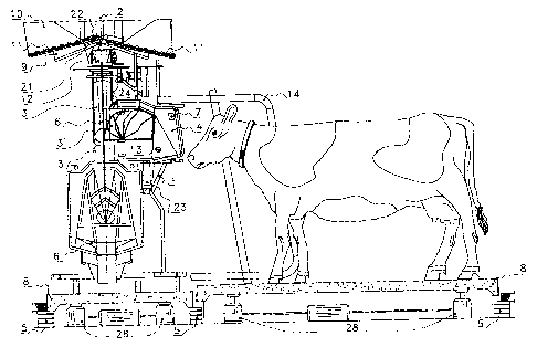
Figure 1 shows schematically a device for supplying
feed to animals, in particular but not exclusively cows. The
device comprises a framework 1 which, in the embodiment
depicted in Figures 1 and 2, is disposed around a central
axis 2 and has a substantially circular circumference. At the
upper side of the fram@work 1 there are located hoppers 9,
10. For the installation of the hoppers 9, 10 there are made
not further shown provisions on the framework 1. The device
is adapted to be placed in a position, in other words can be
positioned, on a bottom 5, preferably having a floor portion
8, on which an animal can stand.
The framework 1 is preferably provided with
partitions 4 between adjacent feeding troughs 6. The
partitions 4 are possibly detachably disposed on the
framework 1. The partitions prevent an animal from being
, I
CA 02382484 2002-06-14
8
disturbed by another animal during eating from a feeding
trough. Because cows eating from a feeding trough 6 come in
the immediate vicinity of the partition 4, there is provided
a reading device 13 in the partition 4 for reading the data
in a step counter fitted to the cows. Such step counters are
used inter alia for measuring whether or not an animal is on
heat on the basis of the number of steps.
PartitiQn frames 14 (one of which is shown in
Figure 1) extend from the feeding trough over a distance that
equals at least approximately half of the average length of a
cow. The partition frame is preferably made of stainless
steel, although other materials such as synthetic material
may be applied as well. The partition frames 14 prevent
animals standing side by side from leaning too much against
each other.
In the embodiment shown feeding troughs 6 for the
animals are disposed in circular arrangement around the axis
2 in the lower part of the device. By means of the geometry
of the device, in the embodiment shown constituted by a
feeding column, it is achieved that the construction occupies
little space, while the accessibility of the feeding column
to the animals is optimal from all directions. For the sake
of compactness a first number of the feeding troughs 6 are
disposed on the framework in a lower position than a second
number of the feeding troughs 6. As is apparent from Figure
1, the feeding troughs of the first number overlap the
feeding troughs of the second number in a projective view.
The feeding column is further provided with
conveying means comprising a first conveyor 11 and a second
conveyor 3, 3' for conveying feed from the hopper 9
respectively 10 to the relevant feeding trough 6. A
receptacle 12 receives an amount of feed which is conveyed by
the first conveyor 11 from the hopper 9, 10 to the receptacle
12. As a first conveyor 11, an auger, gripper, belt conveyor
or any other device.known per se for conveying feed may be.
i
CA 02382484 2002-06-14
9
used. The first conveyors 11 convey feed from a hopper 9, 10
upwards for obtaining a highly accurate metering. The first
conveyors 11 have supply ends corresponding with the
discharge ends 21 respectively 22 of the hoppers 9
respectively 10. In the embodiment shown the hoppers 9, 10
are disposed around the central axis 2. The discharge ends 21
and 22 of the hoppers 9, 10 alternately stagger in height,
the arrangement being such that the discharge ends of
juxtaposed hoppers 9, 10 partially overlap each other in a
projective view, as is apparent from Figure 1.
A second conveyor 3, 3', preferably constituted by
a tube-shaped chute respectively a channel-shaped chute, is
suitable for conveying the amount of feed from the receptacle
12 to the relevant feeding trough 6. Above the feeding
troughs 6 of the first number, so the lower feeding troughs
6, there is provided a third conveyor 18, preferably
constituted by a tube-shaped chute respectively a channel-
shaped czhute, for conveying feed from the second conveyor 3,
3' to the feeding trough 6. Although there may be provided a
separate third conveyor 18 per feeding trough 6 of the first
number, the third conveyor 18 is preferably disposed so as to
be rotatable around the central axis 2. The rotation is
effected by a drive member 23, e.g. constituted by an
electric motor.
In an analogous manner the second conveyor 3, 3' is
disposed so as to be rotatable around the central axis 2;
this rotation may be driven by a motor 24. Moreover, the
second conveyor 3, 3' is movable from a position in which the
feeding troughs of the second number can be filled to a
position in which the feeding troughs of the first number can
be filled, as is apparent from Figure 2.
For conveying the feed to the tube-shaped chute 3,
3', the receptacle 12 has a bottom which is adapted to be
opened. In the embodiment shown in Figure 3 this is realised
in that the bottom of the receptacle 12 is constituted by two
i.~; ;I
CA 02382484 2002-06-14
halves 16 and 17 which are pivotable about an axis 15. When
the halves 16, 17 move away from each other, there is created
an aperture 18 through which the feed falls into the tube-
shaped chute 3, 3'.
5 The device comprises a drive member 19 for
controlling the opening of the bottom. The drive member 19 is
controlled by a computer 25 which also controls the order of
functioning of the first and second conveyors 11 respectively
3, 3' .
10 The receptacle 12 is provided with a weighing
device 20 known per se for measuring feed present in the
receptacle 12. The weighing device 20 may be a load cell on
which the receptacle 12 bears via e.g. a leaf spring 27 and a
rod assembly 26.
There are provided identification means 7 for
identifying an individual animal. In the embodiment shown the
identification means 7 are disposed in the partitions 4, but
it will be obvious that the identification means may also be
disposed at other places, such as e.g. the feeding troughs 6.
With the aid of the identification means 7 the identity of an
animal present at a feeding trough 6 is determined
automatically. With the aid of correspondence tables stored
in the memory of e.g. the computer, it is possible to supply
e.g. the amount of feed intended for that animal. Said amount
may be determined by means of the weighing device 20. With
the aid of data from the animal identification means 7 the
computer further controls the movement of the tube-shaped
chute 3 so that the latter is located over the right feeding
trough 6. The computer further controls the drive of the
conveyors 11.
For the purpose of giving animals of different
heights access to a feeding trough 6 in a simple manner, the
height of a feeding trough 6 relative to the bottom 5 is
adjustable. To that end a feeding trough may be disposed on
the framework 1 so as to be movable in height, said movement
;
CA 02382484 2002-06-14
11
being realised by e.g. a motor controlled by the computer 25.
For controlling the motor for moving the feeding troughs in
height, the computer 25 may use data from the animal
recognition respectively the animal identification means 7.
Alternatively the floor portion 8 of the bottom 5
may be moved upwards or downwards by means of a lifting
device 28. A raised floor portion 8, even when it is
constituted by a permanently raised floor portion 8, has the
advantage that the cow has not to stand unnecessarily in
excrement. Especially for that purpose the floor portion 8
slopes downwards in a direction away from the device, as
schematically shown in Figure 1.
When the device according to the invention is
suitable for feeding calves, or other animals that are
growing, it is advantageous when there is provided an animal
height measuring means for measuring the height of an animal.
Such an animal height measuring means may e.g. be constituted
by a camera or a light grid. In Figure 2 there are provided
measuring strips 29 (or sensors in the form of strips) which
may be used for height measurement, and possibly for the
control of the mutual height adjustment of feeding trough and
floor portion.
The information from the height measuring means 29
may also be used for controlling a feed metering device
supplying feed in metered portions partially with the aid of
data from the animal identification device 7 and feeding data
stored in the computer 25. In this situation also the
information from an animal weighing device, e.g. a floor
portion designed as a weighing floor. For that purpose the
animal height measuring means and the weighing means comprise
a data conveying means for conveying measurement data to the
computer. The computer is provided with a memory containing
average growth data for the animal species, preferably in the
form of correspondence tables, in relation to weight in
dependence of age, and/or in relation to height in dependence
CA 02382484 2002-06-14
12
of age, and/or in relation to the amount of feed per day per
animal in dependence of age, and/or historical growth data of
an animal, the feed metering device supplying feed in metered
portions with the aid of at least one of said data.
According to the invention, in the device as shown
in Figures 1 and 2 in which several feeding troughs 6 are
disposed around the central axis 2, there are used feeding
troughs having a shape that widens from their entrance
opening towards the central axis 2. This has enormous,
unexpected advantages in relation to the feed intake of
animals. In this situation the degree of widening is
especially such that the front part of the head of the cow
has relatively much lateral freedom, and the entrance opening
is just large enough to allow the passage of the head.
Figure 4 shows schematically a plan view of a
plurality of feeding troughs 6 di.sposed around a central axis
2. The feeding troughs 6 are widening from the entrance side
for an animal. The feeding troughs 6 may also be designed so
as to be deeper in the region of the widened portion than in
the region of the remaining portion. It will be obvious that
the invention is not limited to the shape in the embodiment
shown, but that all widening shapes may be applied.
The invention is not limited to the above-described
embodiments, but it will be obvious that supplements and
modifications within the scope of the claims are possible.
The device may e.g. be provided with a lighting disposed
behind a feeding trough, preferably a central lighting for
all feeding troughs. Besides, the device may be provided with
means for combating vermin, and/or means for preventing the
formation of condensation in the device, and/or means for
cooling an animal. Especially when the device is used by
dairy animals, it has appeared to be advantageous when the
device is provided with means for giving the animal a signal
indicating that the animal is expected at a milk box, said
milk box comprising for example a milking robot.