Language selection

Search

Patent 2382710 Summary

Third-party information liability

Some of the information on this Web page has been provided by external sources. The Government of Canada is not responsible for the accuracy, reliability or currency of the information supplied by external sources. Users wishing to rely upon this information should consult directly with the source of the information. Content provided by external sources is not subject to official languages, privacy and accessibility requirements.

Claims and Abstract availability

Any discrepancies in the text and image of the Claims and Abstract are due to differing posting times. Text of the Claims and Abstract are posted:

  • At the time the application is open to public inspection;
  • At the time of issue of the patent (grant).
(12) Patent: (11) CA 2382710
(54) English Title: FASTENER PROTECTION
(54) French Title: PROTECTION DE FIXATION
Status: Expired and beyond the Period of Reversal
Bibliographic Data
(51) International Patent Classification (IPC):
  • F16B 19/05 (2006.01)
(72) Inventors :
  • ALLEN, TERENCE PAUL (United Kingdom)
  • PARSON, REGINALD DAVID (United Kingdom)
(73) Owners :
  • AIRBUS OPERATIONS LIMITED
(71) Applicants :
  • AIRBUS OPERATIONS LIMITED (United Kingdom)
(74) Agent: SMART & BIGGAR LP
(74) Associate agent:
(45) Issued: 2009-02-03
(86) PCT Filing Date: 2000-08-22
(87) Open to Public Inspection: 2001-03-08
Examination requested: 2005-08-04
Availability of licence: N/A
Dedicated to the Public: N/A
(25) Language of filing: English

Patent Cooperation Treaty (PCT): Yes
(86) PCT Filing Number: PCT/GB2000/003232
(87) International Publication Number: GB2000003232
(85) National Entry: 2002-02-22

(30) Application Priority Data:
Application No. Country/Territory Date
9920306.9 (United Kingdom) 1999-08-27

Abstracts

English Abstract


The invention relates to a sheath (46) for protecting a fastener such as a pin-
tail locking bolt (18) as it is passed
through a passage (14), the sheath (46) defining a first hollow (52) at a
first end for receiving part (28) of the pin-tail locking bolt
(18) and a second hollow (54) at a second end suitable for collecting a
substance such as a sealant (13) in the passage (14).


French Abstract

La présente invention concerne une gaine (46) destinée à protéger une fixation, telle qu'un boulon de blocage à pivot (18), lorsqu'elle est passée à travers une ouverture (14), la gaine (46) définissant une première cavité (52), à une première extrémité, destinée à la partie recevante (28) du boulon de blocage à pivot (18), et une seconde cavité (54), à une seconde extrémité appropriée, destinée à réceptionner une substance, telle qu'un produit de scellement (13), dans l'ouverture (14).

Claims

Note: Claims are shown in the official language in which they were submitted.

7
CLAIMS:
1. A sheath for protecting a fastener as it is passed
through a passage, the sheath defining a first hollow at a
first end for receiving part of said fastener and a second
hollow at a second end suitable for collecting a substance
in the passage.
2. A sheath according to claim 1, in which the sheath
is removable from the fastener after passing through the
passage to expose the part of the fastener which is clean.
3. A sheath according to claim 1 or 2, in which the
sheath comprises an internal barrier to prevent substance
which enters the second hollow making contact with the
fastener.
4. A sheath according to claim 1, 2 or 3, in which
the barrier is an internal wall.
5. A sheath according to any one of claims 1 to 4, in
which the sheath is of circular cross sectional shape.
6. A sheath according to any one of claims 1 to 5, in
which the sheath is provided with at least one rib on its
outer surface.
7. A sheath according to claim 6, in which said at
least one rib is in the form of a circumferential
projection.
8. A sheath according to any one of claims 1 to 7
with a fastener therein.
9. A sheath according to claim 8, in which the sheath
is a push or sliding fit on the fastener.

8
10. A sheath according to claim 8 or 9, in which the
part of the fastener within the sheath has grooving thereon.
11. A sheath according to any one of claims 1 to 10,
in which the fastener is a bolt.
12. The sheath of claim 11, wherein the bolt is a
pin-tail locking bolt.
13. A sheath according to claim 12, in which the
sheath receives a pin-tail part of the pin-tail bolt.
14. A sheath according to claim 13, in which the
pin-tail part of the locking bolt is of a lesser diameter
than a main body of the pintail locking bolt, and the sheath
is of a thickness such that the pin-tail part with the
sheath thereon is similar in outer diameter to the main
body, thereby enabling the sheath to fit over the pin-tail
part and pass through the passage.
15. The sheath of any one of claims 1 to 13, wherein
the substance is a sealant.
16. The sheath of any one of claims 4 to 15, wherein
the internal wall is a bulkhead.
17. The sheath of any one of claims 7 to 16, wherein
the circumferential projection is of annular form.
18. A method for protecting a fastener during movement
through a passage having a substance therein from which part
of the fastener is to be protected, the method comprising
the steps of, positioning said part of the fastener within a
sheath, advancing the fastener and the sheath through the
passage such that the sheath shields said portion of the
fastener from contamination by the substance in the passage,
and then removing the sheath from the fastener.

9
19. A method according to claim 18, in which the
method comprises providing the fastener in the form of a
bolt.
20. A method according to claim 18 or 19, including
providing the fastener in the form of a pin-tail locking
bolt and fitting the sheath on a pin-tail part of the bolt.
21. A method according to claim 18, 19 or 20, in which
the method comprises forming the passage in a plurality of
elements.
22. A method according to any one of claims 18 to 21,
in which the sheath is of greater length than the passage.
23. The method of any one of claims 18 to 22, wherein
the substance is a sealant.
24. The method of claim 19, wherein the bolt is a
pin-tail locking bolt.
25. The method of claim 21, wherein the plurality of
elements are skin panels for an aircraft.

Description

Note: Descriptions are shown in the official language in which they were submitted.


CA 02382710 2002-02-22
WO 01/16494 PCT/GBOO/03232
FASTENER PROTECTION
The invention relates to the protection of a fastener primarily during
placement through
a passage in a plurality of elements where the passage contains a sealing
substance.
A known fastener will now be described with reference to Figures 1 and 2 of
the
accompanying drawings, in which:
Fig. 1 is a schematic cross section of a known pin-tail locking bolt
positioned for
f::stening to sheet elements, and
Fig. 2 is an elevation of the known pin-tail locking bolt of Fig. 1 drawn to a
larger scale.
Referring to Fig 1, it is known for elements such as two sections 10, 12 of an
aircraft
wing skin to be joined together in a fluid-tight manner. A passage 14 is
formed through
the skin sections 10, 12, the passage having a countersink 16 in an outer
surface of the
section 12. The skin sections 10, 12 have a flowable sealant 13 between them
and
sealant is also applied to the countersink 16.
Looking at Fig 2, a pin-tail locking bolt 18 comprises a head 20, a shank 22
of diameter
dl and a pin-tail part 24 of diameter d2, where dl is greater than d2. Towards
one end
26 of the pin-tail part 24 arranged furthest from the head 20, a series of
annular grooves
28 is provided. Towards the end 30 of the shank 22 spaced from the head, a
series of
annular grooves 32 is also provided. A point of weakness 34 defined by a
reduced cross
section is provided between the shank 22 and the pin-tail part 24.
Referring again to Fig 1, the pin-tail locking bolt 18 is advanced through the
passage
14. A pneumatic tool 38 has jaws 40 that receive the grooves 28 of the pin-
tail bolt 18
and has a front face 41 that abuts the skin section 10. The jaws 40 then pull
hard on the
pin tail bolt 18 to clamp the skin sections 10, 12 together. An annular collar
42 is then
swaged onto the grooves 32 in the shank 22, for example, by pneumatic devices
44.
Continued pulling on the pin-tail bolt 18 by the pneumatic tool 38 eventually
breaks the

CA 02382710 2008-01-03
26158-158
2
pin-t.ail part 24 awa_y from the shanl: 22 of the installed bolt 18, at the
point of weakness
34.
However, as the pin-tail bolt 18 is advanced through the passage 14, sealant
13
squeezed into the passage 14 from between the sl:in sections 10, 12 and excess
sealant
applied to the countersink 16 is picked up by and contaminates the grooves 28.
It is
conventional to clean the pin-tail bolt 18 and particularly the grooves 28,
with a rag
prior to applying the pneumatic tool 38. However, such a cleaning operation is
not
efficient and the pneumatic tool 38 generally becomes contaminated by the
sealant
which is undesirable.
An aim of the invention is to protect the fastener against such contamination.
According to a first aspect of the invention there is provided a sheath for
protecting a
fastener as it is passed through a passage, the sheath defining a first hollow
at a first end
for receiving part of said fastener and a second hollow at a second end
suitable for
collecting a substance in the passage.
in that way, when the sheath-covered fastener passes through a passage
occupied, say,
by sealant, the first end of the sheath protects the fastener from
contamination by the
sealant whilst the second end of the sheath can collect sealant.
The sheath can be removed from the fastener after passing through the passage
to
expose the part of the fastener which is clean.
Preferably, the sheath further comprises an internal barrier to prevent
sealant which
enters the second hollow making contact with the fastener.
The ban-ier is preferably an internal wall, most preferably a bulkhead.
The sheath is preferably of circular cross sectional shape.

CA 02382710 2002-02-22
WO 01/16494 3 PCT/GB00/03232
The sheath may be provided with at least one rib on its outer surface. The or
each rib is
preferably in the form of a circumferential projection, for example of annular
form. The
rib arrangement is useful for wiping sealant from the surface of the passage
as the
sheath passes there through.
Preferably the or each rib has a radially outer surface of convex cross-
sectional shape.
Preferably, there are at least two ribs on the outer surface of the sheath.
According to a second aspect of the invention there is provided a sheath
according to
the first aspect of the invention or any of the consistory clauses relating
thereto with a
fastener therein.
The sheath is preferably a push or sliding fit on the fastener. Preferably,
the fit is such
that sealant is unable to pass between the sheath and that part of the
fastener therein.
Where the barrier is provided, the fastener may abut the barrier. In that way,
the barrier
will provide a surface against which the fastener abuts to push the sheath
through a
passage.
Preferably, the part of the fastener within the sheath has grooving thereon.
Preferably, the fastener is a bolt and most preferably, a pin-tail locking
bolt. In the latter
case, the sheath preferably receives the pin-tail part of a pin-tail bolt. In
that way, the
pin-tail part remains protected from contamination by the sealant.
Where the pin-tail part of a locking bolt is of a lesser diameter than the
main body of a
pintail locking bolt, the sheath is preferably of a thickness that makes the
pin-tail part
with the sheath thereon similar in diameter to that of the main body thereby
enabling
the sheath to fit over the pin-tail part and still pass through the passage
for which it is
intended.

CA 02382710 2008-01-03
26158-158
4
According to a third aspect of the invention there is provided a method for
protectinc, a
fastener during movement through a passage having a substance therein from
which
part of the fastener is to be protected, the method comprising the steps of,
positioning said part of the fastener within a sheath, advancing the fastener
and the
sheath through the passage such that the sheath shields said portion of the
fastener
from contamination by the substance in the passage, and then removing the
sheath from
the fastener.
Preferably, the method comprises providing the fastener in the form of a bolt,
most
preferably a pin-tail locking bolt.
In the latter case, the method may comprise the step of fitting the sheath on
the pintaii
part of the bolt.
Preferably, the method comprises forming the passage in a plurality of
elements such as
skin panels for an aircraft.
The sheath may be of greater length than the passage.
Fastener protection in accordance with the invention will now be described by
way of
example with reference to the remaining accompanying drawings, in which;
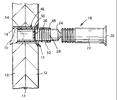
Fig 3 is a cross section of a sheath in accordance with the invention fitted
onto the
pin-tail locking bolt of Fig 2.
?5
Fig 4 is a cross section of a further sheath in accordance with the invention.
Referring to Fig 3, the pin-tail locking bolt 18 of Fig 2 has a sheath 46
fitted thereto.
The sheath 46 comprises a cylindrical tube 48 having an interna] bulkhead 50
approximately midway along its length, the tube and the bull:head defining a
first
hollow 52 and a second hollow 54. The sheath 46 is formed from a suitable
plastics
rrtaterial, for example by moulding.

CA 02382710 2002-02-22
WO 01/16494 5 PCT/GBOO/03232
The sheath 46 is pushed onto the free end 26 of the pin-tail part 24, so that
the free end
26 abuts the bulkhead 50. The tube 48 is of a length that allows the grooves
28 to lie in
the first hollow 52 covered by the sheath 46. The sheath 46 is of a thickness
such that
the pin-tail part 24 with the sheath 46 thereon is similar in outer diameter
to the shank
22 thereby enabling the sheath 46 to fit over the pin-tail part 24 and pass
through the
passage 14, the passage 14 being dimensioned to receive the shank 22.
The bolt 18 and the sheath 46 are then pushed, sheath first, through the
passage 14 in
the sheet elements 10, 12 of a wing skin, the passage 14 being occupied by
sealant as
described with respect to Fig 1. The second hollow 54 collects sealant 13 as
the sheath
46 moves through the passage 14 but the presence of the bulkhead 50 ensures
that the
sealant 13 does not make contact with the pin-tail part 24. The head 20 of the
bolt 18
sits in the countersink 16 (see Fig 1) and the grooves 28 covered by the
sheath 46 and
the further grooves 32 project from the inner section 10 of the wing skin. The
sheath 46
is then removed from the grooves 28, for example using pliers or grips (not
shown).
The pin-tail bolt 18 is then installed on the sections 10, 12 using the
pneumatic tool 38
in the known manner described earlier. It will be appreciated that by using
the sheath
46, the jaws 40 of the pneumatic tool 38 are no longer in danger of becoming
clogged
with the sealant 13.
Looking at Fig 4, a further embodiment of the sheath 60 is shown. Parts
corresponding
with parts in Fig 3 are given the same reference numerals and only the
differences will
be described. The sheath 60 includes annular circumferential ribs 62. The
annular ribs
62 are arranged towards the leading end of the sheath 46. Each annular wall 62
has an
outer part 64 of convex cross section. In use, the ribs 62 wipe sealant from
the surface
of the passage 14. The outer part 64 may be slightly larger in outer diameter
than the
passage 14 but it resiliently deforms inwardly to give a tight fit between the
passage 14
and the ribs 62.
The sheath 46, 60 may be adapted for use on different types of fasteners if
desired.

CA 02382710 2002-02-22
WO 01/16494 6 PCT/GBOO/03232
The shapes of the sheath 46, 60 in different embodiments may vary from these
shown
and so may the shapes of the first and second hollows 52, 54.

Representative Drawing
A single figure which represents the drawing illustrating the invention.
Administrative Status

2024-08-01:As part of the Next Generation Patents (NGP) transition, the Canadian Patents Database (CPD) now contains a more detailed Event History, which replicates the Event Log of our new back-office solution.

Please note that "Inactive:" events refers to events no longer in use in our new back-office solution.

For a clearer understanding of the status of the application/patent presented on this page, the site Disclaimer , as well as the definitions for Patent , Event History , Maintenance Fee  and Payment History  should be consulted.

Event History

Description Date
Time Limit for Reversal Expired 2017-08-22
Letter Sent 2016-08-22
Letter Sent 2011-05-20
Grant by Issuance 2009-02-03
Inactive: Cover page published 2009-02-02
Inactive: Final fee received 2008-11-14
Pre-grant 2008-11-14
Notice of Allowance is Issued 2008-07-16
Letter Sent 2008-07-16
Notice of Allowance is Issued 2008-07-16
Inactive: Approved for allowance (AFA) 2008-05-13
Amendment Received - Voluntary Amendment 2008-01-03
Inactive: S.30(2) Rules - Examiner requisition 2007-07-03
Amendment Received - Voluntary Amendment 2005-09-30
Letter Sent 2005-08-26
Request for Examination Requirements Determined Compliant 2005-08-04
All Requirements for Examination Determined Compliant 2005-08-04
Request for Examination Received 2005-08-04
Letter Sent 2002-08-29
Inactive: Cover page published 2002-08-21
Inactive: Notice - National entry - No RFE 2002-08-15
Letter Sent 2002-08-15
Application Received - PCT 2002-05-30
National Entry Requirements Determined Compliant 2002-02-20
Application Published (Open to Public Inspection) 2001-03-08

Abandonment History

There is no abandonment history.

Maintenance Fee

The last payment was received on 2008-07-17

Note : If the full payment has not been received on or before the date indicated, a further fee may be required which may be one of the following

  • the reinstatement fee;
  • the late payment fee; or
  • additional fee to reverse deemed expiry.

Patent fees are adjusted on the 1st of January every year. The amounts above are the current amounts if received by December 31 of the current year.
Please refer to the CIPO Patent Fees web page to see all current fee amounts.

Owners on Record

Note: Records showing the ownership history in alphabetical order.

Current Owners on Record
AIRBUS OPERATIONS LIMITED
Past Owners on Record
REGINALD DAVID PARSON
TERENCE PAUL ALLEN
Past Owners that do not appear in the "Owners on Record" listing will appear in other documentation within the application.
Documents

To view selected files, please enter reCAPTCHA code :


To view images, click a link in the Document Description column. To download the documents, select one or more checkboxes in the first column and then click the "Download Selected in PDF format (Zip Archive)" or the "Download Selected as Single PDF" button.

List of published and non-published patent-specific documents on the CPD .

If you have any difficulty accessing content, you can call the Client Service Centre at 1-866-997-1936 or send them an e-mail at CIPO Client Service Centre.


Document
Description 
Date
(yyyy-mm-dd) 
Number of pages   Size of Image (KB) 
Representative drawing 2002-08-19 1 8
Abstract 2002-02-21 2 61
Claims 2002-02-21 3 69
Description 2002-02-21 6 202
Drawings 2002-02-21 2 37
Claims 2008-01-02 3 86
Description 2008-01-02 6 206
Representative drawing 2009-01-18 1 9
Reminder of maintenance fee due 2002-08-14 1 109
Notice of National Entry 2002-08-14 1 192
Courtesy - Certificate of registration (related document(s)) 2002-08-14 1 112
Reminder - Request for Examination 2005-04-24 1 116
Acknowledgement of Request for Examination 2005-08-25 1 177
Commissioner's Notice - Application Found Allowable 2008-07-15 1 164
Maintenance Fee Notice 2016-10-02 1 178
PCT 2002-02-21 7 259
Correspondence 2008-11-13 1 38