Note: Descriptions are shown in the official language in which they were submitted.
CA 02383383 2002-03-13
WO 01/19622 PCT/US00/25170
BINDER MECHANISM
BACKGROUND OF THE INVENTION
Binders, including those attached in folders, traditionally have opposing ring
halves that may separate and come together to form open or closed loops. The
ring halves are
received within holes punched through a stack of paper or the workpiece to be
temporarily
bound by the closed loops. Traditionally, ring binders have half rings mounted
on the springs
that are biased against each other by a cover. The ring halves may be pulled
apart from each
other, targeting the leaf springs to an opened position. The ring halves may
also be pushed
towards each other, targeting the leaf springs to a closed position.
Typically, the ring halves
will snap between the open and close positions.
U.S. Patent No. 2,179,627 discloses a loose leaf binder with toggle plates
mounted with a spring back. A handle rotates a pinion to move the toggle
plates longitudinally
relative to each other, together with curved sheet retaining prongs attached
to the toggle plates.
As the toggle plates are moved, a projection cams a toggle plate to open the
rings formed by
the retaining process. Upon further rotation of the handle, the toggle plates
are forced by the
spring back to return their relative angle or position.
2 0 SUMMARY OF THE INVENTION
A binder mechanism comprises a first ring assembly and a binding portion. The
first ring assembly includes at least one first ring half. At least the first
ring assembly or the
binding portion are a pivotable half that is pivotable with respect to the
other to a locked
position about a first longitudinal axis. In the locked position, the first
ring half is engaged
2 5 with the binding portion cooperatively defining a loop that is
substantially closed to retain a
stack of papers or a workpiece. The first ring assembly and the binding
portion are lockable
with respect to each other in the locked position to prevent pivoting of the
pivotable half from
the locked position. At least one of the first ring assembly and the binding
portion is movable
with respect to the other from the locked position in an unlocking direction
oriented at less than
3 0 180 ° from the longitudinal axis to permit the pivotable half to
pivot about the longitudinal axis
to an open position in which the loop is substantially open.
Preferably, the binding portion includes a second ring assembly that has at
least
one second ring half disposed generally laterally from the first ring half
forming at least one
ring half pair. The ring half pair forms the loop. Preferably, the first ring
assembly is
- 1 -
CA 02383383 2002-03-13
WO 01/19622 PCT/US00/25170
resiliently biased towards the open position. A spring may be provided
connected between the
first ring assembly and the binding portion for biasing the first ring
assembly towards the open
position. Preferably, at least one first ring half includes at least one first
locking half and
the binding portion includes a second locking half lockable to the first
locking half. The second
locking half is unlockable from the first locking half by moving either the
first ring assembly
or the binding portion in the unlocking direction. Preferably, the second ring
assembly includes
the second locking half.
Additionally, at least one of the first and second locking halves of the ring
half
pair may include a protrusion and the other of the ring half pair may include
a stop. The
protrusion would be engageable against the stop in the locked position to
prevent pivoting of
the pivotable half about the first longitudinal axis. Further, at least one
first ring half may
include a proximal ring half disposed relative to the locking half such that
the proximal ring
half contacts the binding portion prior to the locking half when the pivotable
half is pivoted
towards the locked position. Preferably, the proximal ring half is not
lockable to the binding
portion in the locked position.
The first ring assembly may also include a first platform to which the
proximal
and locking portions are mounted. The proximal ring halves are preferably
mounted on the
platform in a pivoting direction about the longitudinal axis and are closer to
the binding portion
than the locking half. Additionally, the platform is preferably resiliently
deformable such that
2 0 in the locking position the platform biases the proximal portion against
the binding portion and
the locking portion away therefrom in the closed position. More preferably,
proximal ring
halves are positioned on each side of the locking half. Additionally, a cam
engageable with at
least one of the first ring assembly and the binding portion may be provided
to cam the ring
assemblies generally along the longitudinal axis to lock in the locked
position.
2 5 Preferably, the first ring assembly and the binding portion are each
pivotably
connected to a base. More preferably, the pivotal connection is a pinned
hinge. The binding
portion may be pivotably connected to the base about a second longitudinal
axis substantially
parallel to the first longitudinal axis. Preferably, the base includes a first
base portion pivotably
connected to the first ring assembly, a second base portion pivotably
connected to the binding
3 0 portion, with the first and second base portions connected to each other
and longitudinally
movable with respect to each other in the unlocking direction.
A pivot spring may be provided to resiliently bias the first ring assembly
towards the open position about the first longitudinal axis. Additionally, a
translation spring
may be provided for biasing the first base portion with respect to the second
base portion in a
- 2 -
CA 02383383 2002-03-13
WO 01/19622 PCT/US00/25170
locking direction opposite from the locking position. This retains the first
locking half in
locked association with the binding portion when in the locked position.
A lever may also be provided connected between the first ring assembly and the
binder portion such that rotation of the lever displaces the first ring
assembly with respect to
the binding portion in the unlocking direction. Preferably, the lever has a
blocking portion to
block relative movement in the unlocking direction between the first ring
assembly and the
binding portion.
In another embodiment, the binder mechanism includes a first ring assembly
pivotable along a first longitudinal axis. The first ring assembly includes at
least one first ring
l0 half. A second ring assembly is provided that includes at least one second
ring half disposed
generally laterally from the first ring half forming at least one ring half
pair. The first and
second ring assemblies are lockable with respect to each other in a locked
position in which the
ring half pair defines a loop that is substantially closed to retain a stack
of papers or workpiece.
At least one of the first and second ring assemblies is movable with respect
to the other in an
unlocking direction oriented at less than 180 ° from the longitudinal
axis to permit the first ring
assembly to pivot about the longitudinal axis to an open position in which the
loop is
substantially open.
DESCRIPTION OF THE DRAWINGS
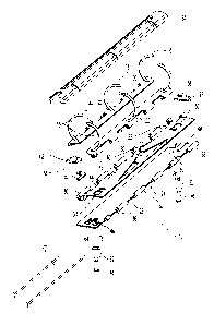
2 o Fig. 1 is an exploded perspective view of a binder mechanism constructed
according to the present invention;
Fig. 2 is a top view of the binder assembly with the cover removed in a
partially closed position;
Figs. 3 and 4 are side views of a button of the binder mechanism;
2 5 Fig. 5 is a top view of the binder mechanism with the cover removed in an
unlocked longitudinal position;
Fig. 6 is a side view thereof;
Fig. 7 is a end view thereof;
Fig. 8 is a top view of the binder mechanism in a closed position;
3 o Fig. 9 is a end view thereof;
Fig. 10 is a top view of the cover of the binder mechanism;
Fig. 11 shows the under side of an alternative embodiment of a binder
construction constructed according to the present invention;
Fig. 12 is a cut-away bottom view of the base thereof;
- 3 -
CA 02383383 2002-03-13
WO 01/19622 PCT/US00/25170
Fig. 13 is a cross-sectional view taken through line XIII-XIII; and
Fig. 14 is a cross-sectional view taken through line XIV-XIV.
DETAILED DESCRIPTION OF THE PREFERRED EMBODIMENTS
Refernng to Fig. 1, the preferred embodiment of a binder mechanism 10 of
the present invention includes opposing binder portions, which are preferably
a left and a
right ring assembly 12 and 14. Each ring assembly 12 and 14 includes at least
one, and
preferably three, ring halves 16 and 18. The ring halves are mounted to
platforms, which
are preferably pivotable leaves 20 and 22. The ring halves 16 and 18 are
preferably welded
or brazed to the leaves, but can be fixed by alternative methods, such as
derivating. Each
ring half 16 and 18 is preferably curved, but may have a different shape, such
as straight
portions, or may have complex curves.
The ring assembly 12 and 14 are pivotably connected to base 24, which
includes inner slider 26 and outer slider 28. Both the leaves 20 and 22 and
the base portions
or sliders 26 and 28 include hinge knuckles 30 spaced by recesses 32. The
knuckles 30 of
the left leaf 20 are intermeshed with the knuckles 30 of the inner slider 26
and the recesses
32 thereof, vice versa. Similarly, the knuckles 30 of the right leaf are
intermeshed with the
knuckles 30 of the outer slider 28 and the recesses 32 thereof, and vice
versa. Hinge pins 34
2 0 are received through aligned holes 36 for each of the intermeshed
knuckles, forming hinges
38. Preferably, the hinges 38 are penal hinges as shown, however, separate
butt hinges may
be attached to the leaves and sliders of a suitable hinge type include living
hinges. The
preferred leaves 20 and 22 and sliders 26 and 28 are formed from sheet metal,
with rolled
hinges. The preferred sheet metal in the leaves 20 and 22 are doubled over
each other in the
2 5 preferably flat portion thereof to which the ring halves are mounted to
provide additional
structural support thereto. Alternately, these components may be welded, or
otherwise
formed, from metals, plastics or other suitable materials. The leaves,
described above are
preferably stiff yet elastic.
The inner slider 26 includes rotational springs 40, which are preferably
3 0 disposed towards the center thereof. The springs 40 are preferably leaf
springs cut out from
the sheet material of the inner slider 26. Springs 40 are bent towards the
leaves 20 and 22,
biasing the leaves 20 and 22 to move the opposing ring halves 16 and 18 from
each other
towards an open position. As shown, springs 40 preferably contact the
underside of the
leaves 20 and 22. As shown in Fig. 2, springs 40 are preferably tapered
towards their free
- 4 -
CA 02383383 2002-03-13
WO 01/19622 PCT/US00/25170
ends 42, such that they are softer near the free end 42 and stiffer where they
meet the plate
portion 44 of the slider 26. The free ends of the leaf spring preferably abut
the leaves 20
and 22 adjacent the center ring halves 18.
Referring to Fig. l, rivets 46 extend through openings 48 and 50 in the outer
and inner sliders 26 and 28. Openings 48 have a similar diameter to the rivets
to preferably
restrict movement between the outer slider 28 and the rivets 46. Openings 50,
however, are
longitudinally longer than the diameter of the rivets 46 to allow longitudinal
sliding of the
inner slider 26.
Beyond the base 24, the rivets 46 pass through spacers or standoffs 52 which
l0 abut cover 54. The cover 54 is supported by standoff 52 at a predetermined
height above
the base 24. The rivets 46 thus preferably maintain the entire structure of
the binder
mechanism 10 during an assembled configuration. Preferably, the rivets 46 are
also passed
through a folder, such as through the spine, front or back cover.
Translation spring 56 is preferably compressed between spring seats 58 and
60, which are preferably upstanding portions of the inner and outer sliders 26
and 28.
Translation spring 56 biases the sliders 26 and 28 longitudinally with respect
to each other
in a blocking direction, which is explained below, retaining ring halves 18 in
locking
association. In the preferred embodiment, the longitudinal direction is
substantially parallel
to the hinge axis of hinges 38.
2 0 A button 62 is pivotably mounted on the base 24. Preferably, the button 62
is pivotably mounted to the outer slider 28, preferably to lever pivotable
bracket 64. As
shown in Fig. 3, a pivot pin 72, which may be a separate pin, or formed as
part of the button
62 or bracket 64, pivotably joins the button to the bracket. The button 62 has
a depressable
portion 66 and a button cam portion 70, which is preferably in the back
surface of the button
2 5 68, which most preferably is part of a laterally extending extension 70.
Button cam portion
70 is disposed adjacent upstanding base cam 74, most preferably is fixed to
the inner slider
26. The button 62 and the base cam portion 74 are associated such that when
the button
portion 66 is depressed, the button pivots back against the base cam portion
74, displacing
the inner slider 26 in an unlocking direction with respect to the outer slider
28, as the button
3 0 62 pivots about its axis on the outer slider 28.
The button 62 also includes a blocking portion 76, which extends through
opening 78 in the outer slider 28 of the base 24. The forward end of the
blocking portion is
adjacent a blocked edge 80 of the inner slider 26 to prevent or limit
longitudinal
displacement of the inner slider 26 with respect to the outer slider 28 upon a
force supplied
- 5 -
CA 02383383 2002-03-13
WO 01/19622 PCT/US00/25170
and directly against the ring halves 16 and 18. As shown in Fig. 4, the button
62 is
depressed, the blocking portion 76 is lifted out of the opening 78 and beyond
the blocked
edge 80, allowing the slider 26 to be displaced by the extension 70 of the
button.
Refernng to Fig. 5, the button 62 is shown depressed, with the inner slider
26 and the left leaf 20 translated rearwardly, in an unlocking direction, and
generally
aligned with the hinge axis 38, further compressing the translation spring 56,
whereas in
Fig. 2, the left and right leaves 20 and 22 and opposing ring halves 16 and 18
are
substantially aligned in lateral direction, and Fig. 5, the ring halves 16 and
18 and leaves 20
and 22 are offset by a distance sufficient to unlock the locking rings 18 from
each other.
l0 The base includes a translation stop 81 mounted to rivet 46, which prevents
further movement of the inner slider 26 past the longitudinal position at
which the present
pair of ring halves 16 and 18 are aligned with each other. A button spring 82
is preferably
mounted to the rivet 46 and has a leaf spring portion that biases the button
in a forward
direction, the position is shown in Figs. 2 and 3.
Refernng to Fig. 5, locking rings 18 preferably have locking portions 84 at
the forward ends, which are configured to cooperatively lock to each other
when the rings
are in a closed position, as shown in Figs. 8 and 9. The locking portions 84
most preferably
include protrusions 86 and stops 88. When the locking portions are locked
together, the
protrusion extends laterally into a recess of the locking portion 84 of the
opposite ring halve
2 0 18, and engages the locking stop 88 thereof, such that pivoting of the
ring halves of the
open position, as shown in Fig. 5, is prevented.
In an alternative embodiment of the invention, the locking portions 84 may
be disposed in other parts of the binder mechanism 10, such as in the base,
and they include
other suitable locking mechanisms as known in the art. Preferably, however,
the locking
2 5 portions 84 dispose the tips of the locking rings 18 so that the locking
rings 18 may be
pressed together by the fingers of a user, as shown in Fig. 2, in which the
rings 16 and 18
are laterally aligned with each other, and longitudinally the locking
position. Preferably, as
shown in Fig. 1, the locking portions 84 also include a locking cam 90 facing
the opposing
locking portions 84 to cam or displace the locking portions 84 longitudinally
with respect to
3 0 each other, permitting the locking portions 84 to slide into engagement
with each other.
As shown in Fig. 5, ring halves 16, preferably do not have locking portions,
but instead have surfaces 92 that are preferably angled to permit the ring
halves 16 to slide
in the unlocking direction with respect to each other. The proximal ring
halves 16 are
preferably not lockable to each other. The surfaces 92 face each other, and
preferably lock,
- 6 -
CA 02383383 2002-03-13
WO 01/19622 PCT/US00/25170
but may be curved or may include several flat surfaces disposed at different
angles and
including a surface that is parallel to a longitudinal axis of the binder
mechanism 10. In an
alternative embodiment, all of the ring halves 16 and 18 may include locking
portions, but it
is preferred that only one of the opposing pairs of ring halves include the
locking portions to
facilitate closing and locking of the binder.
As shown in Figs. 5 and 7, the ring halves 16 and 18 are mounted to leaves
20 and 22, such that the ring halves 16 are proximal ring halves that are
closer to their
respective opposing proximal ring halves 16 while the locking ring halves 18
are disposed
further from each other. The leaves 20 and 22 are preferably stiff but
flexible and resilient
enough to be deformed by squeezing the locking ring halves 18 together as
shown in Fig. 2,
after the proximal ring halves 16 have contacted each other and they are in
the pivoting
direction about the longitudinal axis. Thus, in the locked position shown in
Figs. 8 and 9,
the platform passes the proximal ring halves against each other, while passing
the locking
ring halves in a direction away from each other. As the binder is forced at
the closed
position, the proximal ring halves 16 have contacted each other preferably
before the
locking ring halves 18 contact each other.
As shown in Fig. 9, when the ring halves 16 and 18 are in a closed and
locked position, the opposing ring halves cooperatively define a_ loop that is
substantially
capable of being closed within a hole punched stack of paper or the workpiece.
As
2 0 described, the locking portions 84 prevent pivoting of the ring assemblies
away from the
locked position towards the opened position.
To open the binder, a user depresses a button 62, which pivots about pivot
pin 72, and translates the leaves 20 in the unlocking direction. This
displacement separates
the locking portions 84 of locking ring halves 18, allowing the springs 42 to
pivot the ring
2 5 assemblies, including leaves 20 and 22 in an open direction in which the
opposing pairs of
ring halves no longer form a closed loop, but instead define a substantially
opened loop to
allow loading and unloading of paper or the workpiece. At least one of the
ring assemblies
is movable with respect to the other ring assembly in an unlocking direction
oriented less
than 180° from the longitudinal axis, still more preferably less than
about 30° from the
3 0 longitudinal axis, and most preferably less than about 10 ° from
the longitudinal axis.
Leaves 20 and 22 preferably are not forced against each other, and may have a
gap between
each other as shown in Fig. 8. The open position immediately after separation
of the pairs
of opposing ring halves while the button is still depressed is shown in Figs.
5-7. The ring
assemblies preferably move longitudinally with respect to each other by at
least about half
CA 02383383 2002-03-13
WO 01/19622 PCT/US00/25170
of the width of the ring halves. The locking portions are configured to
disengage at least at
this point. As can be seen, the locking portions 84 of the opposing locking
ring halves 18
are longitudinally out of alignment, and have been displaced with respect to
each other
sufficiently to longitudinally move the locking portion 84 to clear the
locking stop 88. In
an alternative embodiment, we have different means of moving or sliding the
ring
assemblies with respect to each other longitudinally, such as a cam, a spring,
or a handle
that permits direct pulling of one or both of the ring assemblies. However,
the system
described with a translation blocking member, such as blocking portion 76, is
preferred to
prevent accidental opening of the binder mechanism that may be caused, for
example, when
the binder mechanism falls to the floor.
Referring to Fig. 10, the cover 54 includes lateral slots 94 and 96 on the
left
and right sides thereof. The slots 96 preferably have a substantially uniform
length such
that the cover may be assembled to receive the ring halves 16 and 18 that are
disposed on
the right leaf 22, allowing them to pivot between the opened and closed
positions about the
longitudinal axis. The slots 94 on the left side of the cover, have a wire
portion towards the
interior of the slot to permit the ring halves 16 and 18 that are mounted to
the left leaf 20 to
transmit longitudinally therein. The cover also has a button recess 98 to
expose the upper
surface 66 of the button, to allow the user to suppress the button 62.
Referring to Figs. 11-14, another embodiment 100 of the binder mechanism
2 0 constructed according to the present invention includes a base 102, which
is preferably
interval construction and may be labeled as a unitary piece. Non-locking ring
halves 104
and locking ring halves 106 are preferably pressed, otherwise secured to
shafts 108 and 110.
As shown in the figures, the free ends of the non-locking ring halves 104
comprise a chain
of angled surfaces facing meshable angled surfaces in the opposing ring halves
104.
2 5 The shafts 108 and 110 are snapped into slots 112, which preferably
perform
as pushing to allow pivoting between locked and unlocked positions about a
longitudinal
axis of the shafts 108 and 110. Ring halves 104 and 106 are received through
openings 114
and 116. Openings 114 are wider in the longitudinal direction than openings
116, to permit
longitudinal sliding of the shaft 108 with respect to the base 102 and the
shaft 110.
3 0 A translation spring 118, which is preferably a compression spring in this
embodiment, but which may be an expanded spring in another embodiment, is
disposed
between preferably swaged barbs 120, which extend regularly from the shaft
108, and wall
122 of the base. Thus, spring 118 longitudinally biases the shaft 108 and the
rest of the ring
assembly in the locking longitudinal direction. Preferably, the end 144 of
shaft 108
_ g _
CA 02383383 2002-03-13
WO 01/19622 PCT/US00/25170
contacts the wall 146 of the base to prevent longitudinal movement of the
shaft 108 past the
point at which the opposing pairs of ring halves 104 and 106 are aligned with
each other.
This permits a user to compress the ring halves 104 and 106 together to lock
them to each
other, without requiring manual alignment. Torsion springs 124 are engaged
with slots 126
in the shafts 108 and 110 and spring seat 128. The torsion springs bias the
shafts 108 and
110 to rotate the ring halves 104 and 106 away from each other toward the open
position.
The locking ring halves 106 engage and lock the association to prevent this
rotation.
Refernng to Fig. 12, the button 130 is received through opening 132 on the
top of the base and has pivot pins 134 which snap into brackets 136 of the
base. The button
1 o spring preferably biases the button to an inactive position with respect
to the base 102,
similarly to the first embodiment. The button has a blocking portion 138,
which preferably
engages in an opening below, which is shown in Fig. 11. A ring assembly
actuating portion
140 extends laterally from the button and is positioned with respect to the
pivot pin 134 to
engage slot 142 of shaft 108. When the button is depressed, it pivots about
pivot pins 134,
and the extension 140 forces the shaft 108 in an unlocking direction away from
the button
to disengage the locking portions of the locking ring halves and allow both
shafts to rotate
with their respective ring halves 104 and 106 to the open position.
The binder mechanisms 10 and 100 are preferably riveted or otherwise fixed,
such as by gluing, screwing, or other known in the art, to a folder 83 shown
in Fig. 7. A
2 o folder is not shown attached to the binder mechanism 100 of the second
embodiment,
however, post 148 preferably is provided in the interior of the base 102 to
permit attachment
to the spine or cover or other portion of the folder to produce a complete
ring binder.
Although each embodiment includes platforms such as leaves 20 and 22 or
shafts 108 and 110, that position opposing the locking ring halves in each
pair pivotably
2 5 further from each other than the non-locking ring halves, alternative
embodiments may have
certain locking ring half pairs positioned further from each than other
locking ring half
pairs. Still further embodiments may have all of the proximal ring halves in
alignment with
each other to contact each other at the same time when the binders are closed.
The preferred
embodiment, however, ensures that all of the ring halves will meet in the
closed position
3 0 upon squeezing the locking ring halves that are further apart or the
distal pair of ring halves,
to the closed position. Binder mechanisms constructed according to the present
invention
may provide easy closing without the proximal ring halves snapping together,
as occurred
in traditional binders in which the proximal ring halves are toggled through
opened and
closed positions. Also, the actuating button allows single handed opening of
the binder
_ g _
CA 02383383 2002-03-13
WO 01/19622 PCT/US00/25170
rings. In an alternative embodiment, however, more than a single button may be
provided,
or more than a single means of opening the ring halves may be provided.
One of ordinary skill in the art can envision numerous variations and
modifications. All of these modifications are contemplated by the true spirit
and scope of
the following claims.
- 10 -