Note: Descriptions are shown in the official language in which they were submitted.
CA 02383861 2002-03-04
WO 01/17671 PCT/US00/24143
APPARATUS AND METHODS FOR THE PRODUCTION OF POWDERS
This patent application claims priority of U.S. Provisional Patent Application
Serial
No. 60/152,377 entitled "APPARATUS AND METHODS FOR THE PRODUCTION OF
POWDERS" that was filed on September 3, 1999, the disclosure of which is
incorporated by
reference in its entirety herein.
BACKGROUND OF THE INVENTION
This invention relates to the manufacture of powders. More particularly, it
relates to
explosive electrical discharge methods and apparatus for making ultra fine
powders (UFPs),
also known as nanopowders (commonly identifying mean particle sizes of less
than 1
micron).
Powders of metals, and of derivative substances such as oxides and nitrides,
have
many uses, including manufacture of sintered components, surface coatings,
composite
materials, chemical catalysts, electrochemically active surfaces, pigments,
and electrically-
and thermally-conductive pastes and bonding agents.
Powders of certain metals, notably aluminum and magnesium, are additionally
used as
oxidants in solid rocket propellants, where powder particle size, degree of
agglomeration,
composition and state of surface, and perhaps also the particle crystal
structure, greatly affect
performance. Nanoparticle-metal fuels are known to burn many times faster than
coarse-particle fuels; their more rapid thermal feedback from the flame to the
material
immediately behind it further increases burn rate and makes possible simpler
nozzle designs. It
is further significant that the specific energy content of very small metal
particles exceeds that
of coarse powders due to the mechanical strain of highly curved surfaces, and
that
nanopowders may additionally possess metastable structures such as a partially-
disordered
metal core and/or surface oxide layer. The energies associated with these
structures may both
lower kinetic barriers along the combustion coordinate and contribute to the
overall enthalpy
change, resulting in both faster-burning and more energetic propellants.
Nanometal-based
propellants are additionally less prone to incomplete burning and to the
formation of stags, both
of which are detrimental to the performance of solid rocket motors.
Sub-micron metal particles have high propensity toward partial self sintering,
resulting in an agglomerated product with reduced specific surface. Further,
many metals are
thermodynamically unstable with respect to their oxides and, in some cases,
their nitrides.
Such metals react spontaneously with air, liberating heat. For ultra-fine
powders, the specific
CA 02383861 2002-03-04
WO 01/17671 PCT/US00/24143
surface area is so large that exposure to air may result in run-away
(combustive) oxidation or
nitridation, i.e., the powder is pyrophoric. Metal powders may also react with
moisture, for
example to form hydroxides, or with atmospheric carbon dioxide to form
carbonates. In the
case of metal-based propellants, the metal particles are subject to slow
oxidation by the
oxidant itself (e.g., ammonium perchlorate).
To hinder such degradative processes, fine metal particles must be protected.
Protective strategies include storage under inert liquids such as kerosene,
chemical
modification of the particle surface to form thereon a protective layer
derived from the metal
itself (intrinsic passivation), and coating the particle with an inert
protective material
(extrinsic passivation). By way of illustration, it is widely known that for
some metals (an
example being aluminum) an effective intrinsic passivation structure is a thin
(typically 1-2
nanometers thick) coherent surface layer of oxide formed by slow reaction of
the metal
particle surface with molecular oxygen at low partial pressure. Surface
nitridation may
similarly be employed in some cases (an example is titanium). Passivation may
in some cases
be achieved by reacting the particle surface with a decomposable carbon-
containing gas,
resulting in the formation of a protective layer of graphitic carbon.
Intrinsic passivation
consumes at least a portion of the metal being protected. Extrinsic protection
is more general,
but often less conveniently applied. Examples are thin films of long-chain
molecules such as
stearic or oleic acid (see, e.g., Seamans et al., U.S. Patent 6,093,309), or
alternatively of
derivative compounds thereof such as salts or esters, or films of polymers
such as
polyfluorochlorocarbons. When exposed to air, the coated particle suffers
surface oxidation
as dictated by its thermodynamics, but the process is slowed by the film.
Thus, the powder
can be exposed to air immediately after coating. A significant advantage of
extrinsic
passivation is that it does not consume the core metal. A limitation is that
the coating may be
deleterious to the end-use of the powder, and its removal may be difficult or
prohibitively
expensive. However, this method can be applied (by way of example) to powders
employed
in solid rocket propellants, where the polymer combusts along with the binder.
Low-friction
polymer coatings (such as poly-fluorochlorocarbons) may also assist
formulation and loading
of the propellant, by reducing its viscosity.
In addition to control of low-temperature self sintering and pyrophoricity,
surface
modification of ultrafine powders may have other benefits. By way of example,
exposure of
the surface of aluminum nanoparticles to controlled trace amounts of water
vapor may result
in the generation of hydrogen, which, in dissociated (atomic) form, dissolves
in the metal
core of the particle. Such particles may have superior combustion
characteristics, enhancing
2
CA 02383861 2002-03-04
WO 01/17671 PCT/US00/24143
their value as oxidants in rocket fuels.
The ability of electric currents to heat, melt, and vaporize conductors has
been known
for almost two hundred years. It is for example the basis of action of the
common electrical
fuse. Electrically heated wires are also used as pyrotechnic initiators in
devices ranging from
automobile air bags to fuel-air explosives.
Explosive electrical disintegration of metal wires (EEW) is believed to have
been
explored in secret in the former Soviet Union and its successor states,
beginning in the late
1970s. Russian Patent 2075371 discloses such a method to produce small
quantities of
unpassivated powders of intermetallic compounds of two source metals. Russian
Patent
2093311 discloses an exploding wire reactor coupled to a centrifugal powder
extraction
system by means of a recirculating gas path. Russian Patent 2120353 discloses
the use of
electrical detonation to produce fine powders, principally metal nitrides.
In the EEW method, an electrical voltage is applied between two points along a
length
of metal wire, such that the resulting current flow causes the wire to be
heated, vaporized,
and converted into a plasma in a brief interval of time, typically
microseconds or less. The
energy necessary to achieve EEW is most effectively delivered from a capacitor-
bank storage
system, and delivered to the load (wire) by means of a coaxial transmission
line via a
triggered spark-gap or other low-impedance, low-inductance high voltage
switch.
The phase transitions from solid to liquid to vapor alter many of the
properties of the
metal. Significant is loss of tensile strength. Once the wire has melted, the
forces of gravity
and surface tension will break the metal filament (hence the current path)
unless restrained
from doing so. By way of example is the mechanical inertia of the metal
itself, which
preserves the integrity of the current path long enough for vaporization to
occur. Neutral
metal vapor is not electrically conductive, however. Thus, current flow (hence
further
heating) will cease when the metal vaporizes unless ionization is initiated,
to form a plasma.
Primary ionization is largely thermal and photonic. It is followed by
secondary
ionizations that result in essentially complete ionization of the conduction
path enabling the
heating current to continue to flow. The resulting plasma may reach
temperatures in excess of
ten thousands degrees Kelvin but has an initial density substantially the same
as the bulk solid
metal, and hence possesses high internal dynamic pressure. Confinement of the
plasma during
the heating phase may be assisted by magnetostriction. Significantly, when the
energy storage
system has discharged any magnetostrictive force disappears. The dense,
superheated plasma
then explodes outwards into the surrounding medium, preferably a cold, high-
pressure inert gas
or even a liquid. The resulting adiabatic cooling of the metal vapor, assisted
by heat transfer to
3
CA 02383861 2002-03-04
WO 01/17671 PCT/US00/24143
the bath medium, causes the vapor to condense very rapidly into an aerosol of
ultra-fine
particles. The mechanism of disruption of the metal in the EEW process is thus
fundamentally
different from that of normal vaporization, which is the relatively slow
(isothermal) boiling or
sublimation of metal from the surface of the conductor.
The mechanism of subsequent solid-particle formation in EEW is also different
from
that in conventional gas-phase processes, notably in the speed with which it
occurs. Rapid
cooling of a material is commonly referred to as "quenching". It is known that
quenching of
many molten alloys produces non-equilibrium structures, i.e., strained
lattices containing high
concentrations of defects. Such materials are referred to as "metallic
glasses". Normally, pure
metals do not form quench glasses because their lattice relaxation rates are
faster than
commonly-achievable quench rates (typically 103-10~°C/sec). However,
quench rates in EEW
are so high (up to 109°C/sec) that non-equilibrium lattices might
indeed result even with pure
metals. Such metal powders would be characterized by metastable "excess"
energies,
technically energies of re-crystallization or of other phase transitions,
which would be released
as heat in any subsequent relaxation of the powder, for example during heating
or combustion.
Thus, it is possible that EEW metal powders not only combust very much more
quickly than
coarser powders made by other methods, but that their combustion energy per
unit mass is also
greater. This may be significant to rocket propulsion.
The commercial development of ultra-fine metal powders and applications
therefor is
still in its infancy. There remains significant room for further development
of such powders
and for improvements in the methods and apparatus to efficiently manufacture
such powders.
BRIEF SUNINIARY OF THE INVENTION
In one aspect the invention is directed to an apparatus for the production of
powder
from a wire. The apparatus includes a substantially closed loop recirculating
gas path having
a first portion extending between a reaction chamber in which an initial
particulate is
generated by an EEW process and an extractor which extracts at least a portion
of such
particulate from the recirculating gas. A second portion of the path returns
from the extractor
to the reaction chamber. A wire source is located external to the reaction
chamber and
delivers the wire along a wire path extending into the chamber and having an
upstream
portion isolated from the recirculating gas in the reaction chamber. A first
electrode has an
aperture circumscribing the wire path within the reaction chamber. A second
electrode is
proximate a terminal end of the wire path within the reaction chamber. An
electrical energy
4
CA 02383861 2002-03-04
WO 01/17671 PCT/US00/24143
source is coupled to the first and second electrodes to selectively apply a
discharge current
between the first and second electrodes to explode a length of the wire to
form said initial
particulate.
In various implementations of the invention, a turbine may be located within
the gas
path upstream of the reaction chamber and downstream of the extractor. At
least the first
portion preferably includes cooled surfaces for removing heat from particles
moving
therealong. This may include a cooled helicoid surface. Preferably, less than
1 % of the initial
particulate returns to the reaction chamber along the recirculating gas path
and most
preferably less than 0.01%. To this end, the extractor may have a filter
element having
upstream and downstream surfaces. A portion of the particulate normally
accumulates on the
upstream surface until a sufficient amount of such portion has caked on the
upstream surface
to allow ejection of such caked particulate and cause such particulate to fall
into a hopper.
The filter element is preferably a porous sintered stainless steel element
having a submicron
pore size and is preferably formed including bundles of tubular elements.
Advantageously, the first electrode has a plurality of such apertures and may
include
at least a portion shiftable to sequentially bring each aperture into the
operational position.
This may be done via rotation about a first axis. The first electrode may
include a body and a
number of inserts mounted within the body, each defining an associated one of
the apertures.
Each insert may be formed of a tungsten-copper sinter and be mounted within
the body from
beneath. Each insert may include a central channel having a relatively wide
upstream portion
and a relatively narrow downstream portion defining the associated aperture.
The first
electrode may be vertically moveable to permit adjustment of an operative
spacing between
the electrodes. The first electrode may include a spider plate and the body
may be mounted
for rotation about the first axis relative to the spider plate. The second
electrode may be
supported by and electrically coupled to the energy source by a conductor
extending through
the chamber wall and within the chamber substantially surrounded by an
insulator. A
substantially nonconductive baffle may surround the insulator and have a slope
which is
directed generally downward toward the outlet effective to guide any stubs
remaining after
explosion out of the chamber. A stub trap may be provided between the chamber
and the
extractor.
Preferably, the wire source comprises a spool from which the wire is drawn
endwise.
The spool may be nonmoving during drawing of the wire. The wire may be
stepwise
advanceable along the wire path. The apparatus may include a wire
straightening mechanism.
The straightening mechanism may include a first engagement member receiving
wire from
CA 02383861 2002-03-04
WO 01/17671 PCT/US00/24143
the wire source and a second engagement member downstream of the first
engagement
member. During operation, the first and second members may be reciprocally
moveable
relative to each other to place an at least partially inelastic longitudinal
strain on a length of
the wire between the first and second engagement members. The strain may be
between 1%
and 10% of a yield strain. The first and second engagement members may
comprise first and
second clamps which are closeable to grasp the wire and openable to release
the wire. In
operation, one such clamp may be fixed along the wire path and the other such
clamp may be
moveable by an actuator between a first location in which the other clamp
grasps the wire in
a relatively unstrained condition and a second location in which the other
clamp releases the
wire at said at least partially inelastic longitudinal strain.
Preferably, a processing subsystem is coupled to the extractor. The processing
subsystem includes a processing chamber containing a processing gas and a
plurality of
vessels within the processing chamber. Each vessel may have an upper port and
a lower port
and may be moveable through a plurality of positions. These may include: a
loading position
in which the vessel receives, through its upper port, powder separated by the
extractor; a
processing position in which the processing gas may come into contact with the
powder in
the vessel through the vessel upper port; and an unloading position in which
the vessel
discharges, through its lower port, processed powder. The powder in the vessel
may be stirred
in the processing position. The processing chamber may include a carousel
rotatable through
a plurality of orientations to move the vessels through the plurality of
vessel positions. The
vessel positions may further include a liquid agent delivery position through
which the vessel
receives, through its upper port, a liquid agent which coats and/or chemically
reacts with the
powder and a mixing position in which a mixing element is inserted through the
vessel upper
port to mix the liquid agent with the powder. The foregoing positions may be
coincident or
separate. A transfer vessel, optionally located within the processing chamber,
may couple the
extractor to the processing vessel in the loading position. The transfer
vessel may include
upper and lower ports sealed by upper and lower valves and may include an
evacuation port.
Sampling devices may be provided to withdraw test samples of processed and/or
unprocessed
powder.
Preferably, the wire may pass through a pressure balancing chamber prior to
entry into
the reaction chamber. The pressure balancing chamber may serve to conserve
reaction gas
and serve as an isolator. The isolator may comprise a first conduit receiving
the wire from
upstream and having an inner surface of a first minimum cross-sectional area.
A second
conduit may admit the wire to the chamber interior downstream and has an inner
surface with
6
CA 02383861 2002-03-04
WO 01/17671 PCT/LTS00/24143
a second minimum cross-sectional area. For wire relatively small compared with
the first and
second conduits, these cross-sectional areas may also approximate the annular
cross-sectional
areas between the wire and the conduits. A pressure balancing chamber may
enclose
respective downstream and upstream ends of the first and second conduits and
may have a
gas inlet port. A balancing gas source may be connected so as to introduce a
balancing gas
through the inlet port and maintain an internal pressure of the balancing
chamber slightly -
below an internal pressure of the reaction chamber downstream of the balancing
chamber
along the wire path. The balancing gas may consist essentially of argon,
nitrogen, or mixtures
thereof. A valve may have an open condition in which the wire can pass between
the first and
second conduits and a closed condition in which the valve blocks the wire path
at the gap and
seals the second conduit. The wire may have a circular cross section with a
diameter of 0.40
+/- 0.02 mm at the source. The first cross-sectional area may be 1.5.1 mm2 and
the second
cross-sectional area may be 7.3-17.0 mm2. More broadly, the wire may
advantageously have
a cross-sectional area of about 0.1-0.4 mm2 and the second cross-sectional
area may be
between 130% and 500% of the first cross-sectional area. At least one pressure
sensor may be
provided for determining a difference between the internal pressure of the
balancing chamber
and the internal pressure of the reaction chamber.
In another aspect, the invention is directed to a powder formed by
electrically
exploding an aluminum-containing wire to form an intermediate powder. The
powder
comprises in major part nonaggregated particles. A median characteristic
particle diameter of
the powder is between 0.05 and 0.5 ~.m. Each particle may include a
nonconductive alumina
layer about 1.5 nm to about S nm thick. The particles may be highly spherical
as measured by
an average ratio of major to minor diameter, which is most advantageously less
than 1.1.
In another aspect, the invention is directed to a method for manufacturing an
energetic
powder comprising electrically exploding wire to form an intermediate powder,
of which a
major portion is nonagglomerated and has characteristic diameters between
about 0.05 and
0.5 ~,m and passivating at least an amount of the desired portion of the
intermediate powder,
to render the passivated powder stable enough to be exposed to air at ambient
temperature
without spontaneous combustion.
The passivation may comprise exposing the powder to a passivating atmosphere
containing argon and oxygen while periodically or continuously mixing such
powder to
maintain exposure to such atmosphere while maintaining a temperature of such
powder at or
below 20°C. The passivation may comprise coating the powder to be
passivated with a coat
that retards penetration of oxygen and exposing the coated powder to an
atmosphere
7
CA 02383861 2002-03-04
WO 01/17671 PCT/US00/24143
containing an oxygen concentration high enough so that the powder would
initially combust
absent the coat. The exposure is for a period of time effective to allow the
atmosphere to form
a passivating oxide layer on the powder. The coat may contain a long chain
aliphatic
carboxylic acid. The coat may be removed when the oxide layer has a thickness
effective to
prevent spontaneous combustion in air. The coat may comprise a
chlorofluorocarbon
polymer. The passivation may be performed while cooling the powder and the
time may be
10-30 hours. The wire may be exploded in length of between 15 and 30 cm and a
diameter of
between 0.3 and 0.6 mm. The explosion may be performed in an atmosphere
consisting
essentially of argon or an argon/hydrogen mixture.
The details of one or more embodiments of the invention are set forth in the
accompanying drawings and the description below. Other features, objects, and
advantages of
the invention will be apparent from the description and drawings, and from the
claims.
BRIEF DESCRIPTION OF THE DRAWINGS
FIG. 1 is a partially schematic side overall view of a processing system
according to
principles of the invention.
FIG. 2 is a partially schematic side sectional view of reactor and electrical
subsystems
of the system of FIG. 1.
FIG. 3 is a partially schematic top view of the reactor of FIG. 2.
FIG. 4 is a vertical sectional view of a high voltage electrode assembly of
the system
ofFIG. 1.
FIG. 5 is a vertical sectional view of a grounding electrode assembly of the
system of
FIG. 1.
FIG. 6 is a bottom view of the assembly of FIG. 5.
FIG. 7 is a top view of the assembly of FIG. 5.
FIG. 8 is a vertical sectional view of an electrode insert of the assembly of
FIG. 5.
FIG. 9 is a vertical sectional view of a spark gap apparatus of the system of
FIG. 1.
FIG. 10 is an end view of one end assembly of the gap of FIG. 9.
FIG. 11 is a partial view of a high voltage electrical subsystem of the system
of FIG.
1
FIG. 12 is a top view of the subsystem of 11.
FIG. 13 is a frontal view of a wire feed apparatus of the system of FIG. 1.
FIG. 14 is a partially schematic view of a pressure balancing apparatus of the
system
of FIG. 1.
8
CA 02383861 2002-03-04
WO 01/17671 PCT/US00/24143
FIG. 15A-15F are schematic views of a sequence of operations of the wire feed
apparatus of FIG. 13.
FIG. 16 is a partially schematic sectional view of a turbine compressor of the
system
of FIG. 1.
FIG. 17 is a partial vertically cut away view of an extractor apparatus of the
system of
FIG. 1.
FIG. 18 is a partially schematic view of a processing vessel in a loading
position in a
processing subsystem of the system of FIG. 1.
FIG. 19 is a partially schematic view of a processing vessel in an unloading
position
in the processing subsystem.
FIG. 20 is a partially schematic view of components of the processing
subsystem.
FIG. 21 is a partially schematic top view of a carousel of the processing
subsystem.
FIG. 22 is a schematic view of control/monitoring components associated with
particle generating portions of the system of FIG. 1.
FIG. 23 is a side view of an inductor in the high voltage electrical
subsystem.
FIG. 24 is a top view of the inductor of FIG. 23.
Like reference numbers and designations in the various drawings indicate like
elements.
9
CA 02383861 2002-03-04
WO 01/17671 PCT/US00/24143
DETAILED DESCRIPTION
The invention provides an enhanced method and apparatus for the production of
ultra-fine metal powders, or equivalently of metal oxides, metal nitrides,
metal carbides and
other compounds that might result from reaction of a dense metal plasma with a
surrounding
(bath) gas. A high voltage, high-current, pulsed power source is provided
effective to deliver
a large amount of electrical energy to a metal wire. Preferably, the energy
delivered will
significantly exceed that necessary to evaporate the metal (e.g., by a factor
of about 1.1 to
about 3 in preferred embodiments), a condition referred to as "superheating".
Energy is
delivered over a period of time (e.g., a few microseconds in a preferred
embodiment) short
enough to ensure that the wire disintegrates explosively rather than simply
evaporating.
By way of example, using 26AWG (0.404mm diameter) aluminum wire feedstock
(e.g., alloy 1188 (min. 99.88% pure) tempered to H-18 (dead soft)), exploded
in 10 inch
(25cm) lengths, suitable discharge parameters include an approximately 0.1
Coulomb charge
stored at a potential of 30kV-SOkV on a low-inductance capacitor of
approximately 3
microfarads and discharged through the wire in a time of approximately 2-5
microseconds.
Ultra-rapid quench is achieved by surrounding the exploding wire with a cold,
dense bath
gas. An exemplary bath gas for the production of pure metal nanopowders has a
composition
by volume of 90% argon, 10% hydrogen and is at a temperature of 300 degrees K
and a
pressure of 2-5 atmospheres. Other gases are required if the end product is to
be a metal
compound or other chemical derivative. Such chemically reactive gases include,
but are not
restricted to, oxygen (for production of metal oxide powders), nitrogen (metal
nitrides),
acetylene (metal carbides), and boranes (metal borides). It is also noteworthy
that two or
more pure metals, or pre-existing alloys, can be co-exploded, thereby
producing nanopowders
of intermetallic compounds or alloys that may not be manufacturable by other
means.
Similarly, mixtures of gases may be employed in order to provide mixtures of
corresponding
metal compounds such as nitrides, carbides, oxides and the like.
In all cases, the EEW discharge results in a dense metal plasma which persists
for a
few microseconds. An exemplary temperature is thought to be between 10,000 and
30,000°C
at this point. Magnetically confined plasmas of high density are known to be
dynamically
unstable; such instabilities are referred to as "Z-pinches" or "zeta-pinches".
High-speed
photographs of exploding wires show the characteristic "zig-zag" discharge
arcs of
zeta-pinches.
As the electric current decays (due to discharge of the capacitors), the
internal
pressure of the plasma drives it into the surrounding bath gas at hypersonic
speed. Because of
CA 02383861 2002-03-04
WO 01/17671 PCT/US00/24143
the plasma instability noted above, this expansion will generally not be
uniform or even
radially symmetrical, which may account at least in part for the distribution
of resulting
particle sizes (see below). Thermal evolution of the system is now controlled
by the
competing kinetics of two processes: heat evolution from ion-electron
recombination and/or
chemical reaction of the metal plasma with the bath gas, and heat loss by
combined radiation,
adiabatic expansion and momentum transfer to the bath gas. As ion-electron
recombination
and other chemical processes become substantially complete, the temperature of
the system
falls extremely rapidly, causing condensation of the metal vapor into solid
particles. The
condensation may pass through a very brief transient liquid phase, accounting
for the high
particle sphericity normally observed due to surface tension in the liquid.
As mentioned above, rapid formation of a solid phase from a liquid or gaseous
phase
(a process referred to as "quenching") often results in non-equilibrium
structures. For
example, molten metals sprayed onto cryo-cooled surfaces may solidify to
produce
disordered lattices referred to as "metallic glasses", that have markedly
different mechanical,
thermal, and electrical properties from the crystalline metals. In the present
process, quench
rates are several orders of magnitude greater than are encountered even in
cryo-cooling.
Whereas in conventional cryo-cooling processes for manufacturing metal-alloy
glasses the
cooling rate is typically on the order of 106°C/s, in the EEW
production of powders
advantageous cooling rate during the particle condensation phase is in the
vicinity of 108-
109°C/s. Further, the physical and chemical conditions present in the
plasma are extremely
severe. Hence it is not surprising that the observed properties of the
resulting EEW-powders
are quite different than those of conventional metal powders.
Certain of the metal nanopowders made in an argon atmosphere contain a
significant
"excess" internal energy which is almost indefinitely stable at normal
temperatures but which
can be released by raising the powder to an elevated temperature, normally
well below the
melting point of the bulk metal. When released, this metastable energy may be
sufficient to
cause the powder to melt almost instantaneously, a process referred to as
"temperature
explosion". The self heating property of the metal nanopowders, together with
their small
size and spherical particle shape, gives such powders high commercial value.
For example,
when such powders are formulated into rocket propellants, the released excess
energy adds to
the heat of combustion of the metal, resulting in burn rates, nozzle
pressures, and thrust levels
that may be unattainable by other chemical processes. The mechanisms of
storage and release
of the excess energy may not be understood in detail at this time.
11
CA 02383861 2002-03-04
WO 01/17671 PCT/US00/24143
Certain information exists concerning the sizes of metal and metal oxide
particles
made by EEW These invariably have a rather wide distribution, that may have a
minor
secondary peak (i.e., bimodal). Quantitative understanding of the distribution
is not yet
available. However, it is clear that it is dictated principally by the density
of the plasma and
its dynamics of expansion. Thus, thick wires (meaning O.Smm diameter or
thereabouts)
exploded with small superheats (ratio of electrical energy used to explode the
wire to the
energy of vaporization of the wire (measured from the starting conditions))
(e.g., 1.2 or less)
generate coarse powders (i.e., in the micron range), whereas thin wires (a few
tenths of a mm)
exploded with large superheats (meaning approximately 1.8 or greater) produce
fine powders
(e.g., 0.1 micron diameter or less). High bath gas pressures result in larger
particles than
lower pressures, by hindering the expansion of the plasma. The reason for
bimodality in some
cases is not well understood.
Nano-particulate aluminum made by the preferred EEW method is extremely
pyrophoric, and must be passivated for safe use. Several methods have been
used in the case
of aluminum to achieve such passivation. The first method is controlled
oxidation of the
nanoparticle surface under conditions that produce a dense, coherent
crystalline surface oxide
layer. The preferred atmosphere for this method is argon containing 10-1000ppm
oxygen, to
which the dry metal nanopowder is exposed at atmospheric pressure for a period
of 1-2 days,
during which the powder is kept in a cooled container to maintain a
temperature at or below
20°C. During the passivation process, the powder is slowly stirred to
expose it to the
passivation atmosphere. The resulting powder comprises aluminum nanoparticles
each
having an alpha alumina (a.k.a. corundum, sapphire) surface layer shown by
electron
micrography to be approximately 1.5-Snm thick (see, for example, Y Champion
and J. Bigot,
NanoStructured materials Vol. 10, pp.1097-1110, 1998 (metal vapor condensation
within a
cryogenic medium (liquid Ar))). This layer effectively prevents further
oxidation of the
particle by air, and also renders it resistant to erosion by atmospheric
moisture. A lesser oxide
thickness may result in residual pyrophoric behavior in a oxygen-rich
atmosphere. Greater
thicknesses imply unnecessary depletion of the energy-rich metal core of the
particle.
Passivation may not be required at all for nonreactive metals (e.g., gold).
In a second passivation process, dry unpassivated metal nanopowder is coated
with a
layer of long-chain aliphatic carboxylic acid, of the form CnH2"+~ COOH where
n is preferably
from 10 to 19 (undecylic acid (melting point 30°C) to arachidic acid
(melting point 77°C)),
for example stearic acid C»H35COOH (melting point 60°C). Melting point
and hardness
increase and oxygen permeability decreases with molecular weight. The layer is
applied by
12
W~ ~l/17671 CA 02383861 2002-03-04 pCT/US00/24143
wetting the powder with a solution of the acid in an appropriate solvent,
which is then
evaporated. Solid esters of long-chain organic acids with mono- and poly-
hydroxy alcohols
are also useful. Other organic coatings may be utilized.
In a third passivation process, dry unpassivated metal nanopowder is coated
with a
layer of an organic polymer. The preferred coating is a low molecular-weight
chlorofluorocarbon polymer having a chain of the form (C2F3C1)" with exemplary
opposing
end groups of H and OH or Cl and CC13. An exemplary such
polychlorotrifluoroethylene is
sold by Minnesota Mining and Manufacturing of Minneapolis, MN under the
trademark
KEL-F. This is a hard semi-crystalline polymer with a substantially lower
permeability to
gases, and thus is more effective at retarding oxygen penetration than the
more common
halocarbon polymer such as polytetrafluoroethylene and the fluoroelastomer
sold by DuPont
Dow Elastomers L.L.C. of Wilmington, DE under the trademark VITON. The polymer
may
be formed in situ from appropriate precursors applied in liquid form to the
nanopowder.
The purpose of either the stearic acid or the polymer coat is to retard
penetration of
atmospheric oxygen to the particle surface, such that a slow, controlled
surface oxidation
occurs. The advantage of this method of passivation is that the powder does
not have to be
kept in a controlled atmosphere for a long period of time, as the passivating
oxide layer
forms. The stearic acid may subsequently be removed if required by washing
with an
appropriate non-aqueous solvent. The polymer material would not normally be
removed,
however, because of its insolubility. Hence the polymer coat method is best
suited to
applications where the presence of chlorofluorocarbon polymer is not
detrimental (or may
even be advantageous), for example in some solid rocket propellant
formulations.
It is advantageous for the rapid optimization of the EEW conditions to be able
to
rapidly measure the thermodynamic properties of small samples of the
unpassivated powder
product in situ. If such information is only obtainable by analysis of
passivated powder after
batch processing based on a 1-2 days' incubation cycle, adjusting the reactor
conditions is
extremely slow and tedious, whereas the ability to sample and analyze a few
grams of powder
before passivation and without removing it from the machine permits the
conditions of
pressure, gas composition, electrical energy, etc., to be adjusted very much
more quickly.
To this end, the processing/passivation chamber is equipped with a scanning
differential calorimeter appropriate for measuring heat evolution from the
powder. The
intermediate transfer vessel is equipped with a sampling device for diverting
small aliquots of
powder from the production stream into it. In the simplest embodiment,
charging and
discharging the calorimeter may be done manually, for which purpose the
processing
13
CA 02383861 2002-03-04
WO 01/17671 PCT/US00/24143
chamber is equipped as a glove box. In a more advanced embodiment, powder may
be
transferred to the calorimeter and removed from it after the measurement by
means of a
robotic mechanism or other automated device.
FIG. 1 shows an embodiment of the invention as a self contained, automated
system
20 for manufacturing, extracting, processing, and bottling nanoparticulate
metal powders and
derivative solids such as oxides, nitrides, carbides, borides, hydrides,
alloys, mixed crystals,
intermetallics, and the like. The exemplary system is formed as a single
substantially closed
loop (i.e., allowing minor losses, diversions, and the like). The exemplary
system 20
generally includes the following subsystems:
an EEW reactor subsystem 22;
an EEW discharge subsystem 24;
a high-voltage (HV) electrical subsystem 26;
a reactor gas handling subsystem 28;
a cooling system 29;
a wire feed subsystem 30 for feeding a wire 31 into the reactor;
a product extraction subsystem 32 and a processing subsystem 33 for extracting
and
processing the powder 34; and
a control and monitoring subsystem 36 including a computer 37 for controlling
and
monitoring and logging the other subsystems.
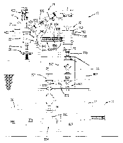
The heart of the EEW reactor 22 is a metal vessel 100 which defines a reaction
chamber (FIG. 2) made from metal appropriate for the enclosed gas (in most
cases, the
preferred metal is T-304 or T-316 stainless steel), with sufficient wall
thickness to safely
withstand the sum of the internal static pressure P (e.g., up to about 150
psia (1 MPa)) and the
superimposed EEW pulse overpressure 0P (e.g., up to about 200 psia (1.4 MPa)
for 100 ~,s).
The vessel includes a cylindrical midsection 102 having a central longitudinal
axis 104 and
fitted with end flanges 106A, 106B. The body includes an outflow (outlet) port
108 about
which is welded an outlet duct 110 having, at its downstream end, a flanged
outlet port 112
defining a reactor outlet. The midsection includes an observation port 114
carrying a viewing
assembly including a sight glass or window 116. The exemplary window is a 5
inch ( 13 cm)
diameter by 1.75 inch (4.4 cm) triple borosilicate-epoxy laminate glass. The
midsection also
includes a pair of flanged instrumentation ports 118 and a pair of flanged
spectroscopy ports
120 (best seen in FIG. 3). FIG. 3 also shows the preferred port orientation
wherein the sight
glass 116 is diametrically opposite the reactor outlet 112, with the
orthogonal instrumentation
14
CA 02383861 2002-03-04
WO 01/17671 PCT/US00/24143
ports at 45 degrees to either side of the observation port about the axis 104.
The spectroscopy
ports 120 are diametrically opposed about the axis 104 each 90 degrees away
from the
observation port and 45 degrees away from an adjacent one of the
instrumentation ports. The
spectroscopy ports advantageously include a fused silica window 122 having at
least about a
0.5 inch (1.3 cm) diameter view to permit spectroscopy readings to be taken
through the
reactor. The cover plates of the ports 118 carry sensors for measurement of
the EEW
discharge parameters. The sensors may include a fast photodiode light
detector, a soft x-ray
detector, and a transient overpressure transducer.
A generally hemispherical upper section 124 of the vessel (FIG. 2) is fitted
with a
mouth flange 126 bolted to the midsection upper flange 106A, and has a flanged
central top
port 128 and a flanged lateral gas inflow (inlet) port 130. The vessel also
includes a circular
upper end (top) plate 132 mated to the top port flange and a circular lower
end (bottom) plate
134 mated to the lower flange 106B. All flanges and plates are preferably
fitted with bolt
circles and seals (for example, O-rings or gasket rings of soft metal, e.g.,
annealed copper)
according to standard engineering practice, enabling the vessel to safely
contain both the
negative (-lAtm gauge, vacuum) and the positive (P+0P) differential pressures
potentially
encountered during reactor operation. Pressure within the reactor may be
measured via a
sensor 136 coupled to the control system data bus.
The vessel also contains an upper electrode assembly 200 and a portion of a
lower
electrode assembly 202 of the discharge system 24. The upper and lower
electrodes, along
with the length of wire 31 therebetween, provide the internal EEW discharge
path. The upper
assembly 200 is mounted to the interior surface 138 of the vessel midsection
whereas the
lower assembly extends through the bottom plate 134 and within a contoured
baffle 140, the
upper surface 142 of which defines a general downward slope toward the outlet
108.
The high voltage electrode assembly 202 (FIG. 4) comprises a central bus-bar
203,
preferably 10-12 inches (25-30 cm) in length, 2 inches (5 cm) in diameter, and
made of
electrolytic-grade copper, an insulator 204 surrounding the bus-bar, and a
mounting flange
205. The assembly is intended to extend through and seal with the reactor
vessel bottom plate
134, but be easily removable for servicing.
The ends of the bus-bar are machined to form tapers 206, and are centrally
drilled and
fitted with thread inserts, preferably 0.5 inch (1.3 cm) in diameter and
threaded 32 tpi (12.6
tpcm). A threaded stud 208, preferably 0.5 inch (1.3 cm) in diameter and
threaded 32 tpi
(12.6 tpcm), is screwed tightly into the upper insert, such that a short
portion of the stud
protrudes from the end of the bus-bar, the protruding portion being preferably
about 0.375
CA 02383861 2002-03-04
WO 01/17671 PCT/US00/24143
inch (1 cm) in length. A replaceable metal electrode disk 210, preferably of
the same metal as
the wire to be exploded, has a smooth polished flat central upper surface
portion and a lower
surface having a compartment of complementary taper to the upper end of the
bus-bar and
having an aperture with a thread insert for receiving the protruding portion
of the stud 208.
The threaded engagement between the bus-bar and the disk via the stud 208
provides high
engagement forces between the complementary tapers so as to produce electrical
contact
between the two of low resistance and high current-carrying ability. Exemplary
disk
dimensions are 4 inches (10 cm) in diameter and 0.75 inch (1.9 cm) thick with
a rounded
perimeter edge joining the upper and lower surfaces.
The insulator 204 is formed of heat resistant and mechanically rigid material
with
high dielectric strength. A preferred material is a glass-epoxy composite such
as G-10 (a
glass-filled epoxy certified by the National Electrical Manufacturers
Association (NEMA) for
applications requiring high tensile strength, high dielectric strength and
stability at elevated
temperatures.) or the like. The insulator preferably has a 5 inch (13 cm)
overall diameter and
has an overall length approximately 2 inches (5 em) less than the bus-bar. A
central axial
bore of diameter preferably slightly (e.g., 1/16 inch (0.16 cm)) greater than
the diameter of
the bus-bar runs the length of the insulator. The bus-bar is sealed into the
insulator such as by
a medium viscosity semi-pliable silicone or epoxy compound, forced under
pressure into the
annular space between the bus-bar and the central bore of the insulator, then
cured in situ.
A lower portion of the insulator is of reduced diameter and is separated from
the
upper portion by an annular shoulder 212. The shoulder is preferably
approximately 0.75 inch
(1.9 cm) in radial span and includes an array of holes fitted with thread
inserts. The shoulder
212 is received in an upwardly-open central compartment of the flange 205 and
is secured
thereto via an array of bolts 214 engaging the shoulder's array of holes. The
flange 205 is
preferably formed of stainless steel 8 inches (20 cm) in diameter and one inch
(2.5 cm) thick
overall.
In addition to an inboard array of counterbored holes for the bolts 214, an
outboard
array of counterbored holes is provided for bolts 216 securing the flange 205
to the reactor
bottom plate 134. The bolts 216 preferably extend into a depending central
boss of the bottom
plate 134 surrounding an aperture which accommodates the insulator. The flange
is
preferably sealed to the insulator by an elastomeric gasket 218 and to the
reactor bottom plate
by a soft copper gasket 220.
The lower portion of the insulator carnes a fast current-pulse transformer 222
for
monitoring the EEW current wave form. This is coupled to a transient digitizer
(not shown),
16
CA 02383861 2002-03-04
WO 01/17671 PCT/US00/24143
thence to the bus of the control and monitoring subsystem. A relatively large
diameter
insulating disk 224 (e.g., glass, ceramic, or G-10) is secured to the
insulator 204 at its lower
end to prevent arc-over from the spark gap (described below) to the
transformer 222 and/or
the bottom plate 134 and components secured thereto.
The grounding electrode assembly 200 (FIG. 5) carries the EEW discharge
current
from the upper end of the exploded segment of wire to the vessel midsection
wall of the
reaction chamber, thence to ground. It further provides a gas flow path from
the upper domed
section of the reactor chamber (where the recirculating gas enters the
reactor) to the central
cylindrical section of the chamber (where the gas entrains the plume of metal
particles
created by the wire explosion and then exits the reactor).
The assembly 200 (FIG. 5) includes a metal spider 230 and an electrode insert
Garner
having a body 231 carned by the spider. The spider comprises a circular rim
232 connected
by a plurality of spokes 233 to an eccentric hub or boss 234, the rim being
machined to an
outside diameter a few thousandths of an inch (hundredths of a mm) less the
inside diameter
1 S of the central section of the reactor vessel into which the spider is push-
fit (the diametric
difference between chamber and spider being exaggerated in the drawing). The
spider is
preferably of cast aluminum, two inches (5 cm) thick and 17 inches (43 cm) in
diameter. The
boss is preferably eight inches (20 cm) across. The spokes are preferably six
in number, with
widths approximately one inch (2.5 cm), providing a low-resistance path from
the boss to the
rim. The spaces between the spokes are effective to allow free passage of gas
from the upper
portion of the reactor chamber to the lower.
The rim of the spider is machined to form a shoulder 235 which defines an
upper
flange at the maximum rim diameter. The maximum rim diameter extends to the
upper
surface of the spider. Below the shoulder a downwardly tapering neck extends
to the lower
surface (underside) of the spider. The tapering surface 236 of the neck is
complementary to
and nested within an inner surface 238 of a ring 240. An upper surface of the
ring faces the
shoulder 235 and is slightly spaced-apart therefrom. The flange portion and
ring have aligned
circular arrays of holes, the latter bearing threaded inserts which receive
bolts 242 securing
the flange to the ring. The ring is provided with a circumferential gap 243
allowing the ring to
be expanded and contracted via interengagement of the tapering surface of the
rim and ring
when the bolts 242 are tightened and loosened. With the assembly 200 in a
desired position,
tightening of the bolts 242 thus produces a radial expansion of the ring 240
by opening the
gap 243 to cause the perimeter surface 244 of the ring to bear against the
interior surface 138
to secure the assembly in a desired vertical location with robust electrical
contact between the
17
CA 02383861 2002-03-04
WO 01/17671 PCT/US00/24143
assembly and the reactor vessel.
The boss 234 of the spider is through-machined with an upwardly-tapering
central
hole defined by a surface 248, around the periphery of which is a circle of
bolt holes with
thread inserts. The surface 248 is coaxial with a central axis 249 of the boss
234 and body
231 and offset from the reactor axis 104 (FIG. 6). The body 231 has upper and
lower surfaces
joined by an upwardly-tapering surface 250 of complementary taper to the
surface 248.
The body 231 preferably carries a plurality of individual inserts 254. Each
insert has a
central axis 255 offset from the axis 249 by the same distance that the latter
is offset from the
axis 104. Each insert 254 is received by mating features of the carrier body
231 (e.g., a
circular compartment extending upward from the bottom surface thereof).
Inserts 254 are
formed of refractory metal such as a 70% tungsten-30% copper sinter or may be
machined
from the same metal as the wire to be exploded in the reactor. The insert has
flat upper and
lower surfaces and an upwardly-tapering perimeter surface 256 (FIG. 8)
complementary to a
taper of the circular compartment of the carrier body 231. A central channel
258 extends
through the insert and has a relatively large diameter upper portion 260 and a
relatively small
diameter lower portion 261. The central channel 258 functions to accommodate
the wire. The
advantageous knife edge-like lower portion 261 serves to provide a large
electrical field
gradient to localize breakdown during initiation of wire explosion. This
provides for a
consistent length of wire being exploded. Each insert 254 includes an array of
threaded
mounting holes 264 which receive machine screws 265 extending through co-
aligned holes in
the body 231. The body includes a channel 266 (FIG. 5) aligned with the
central channel 258
of each insert.
When a given insert has become eroded from extended use, the body 231 may be
rotated about its axis to bring a fresh insert into the operative position
aligned with the axis
104. To provide for accurate registry of the intended insert with the axis
104, for each such
insert there is provided in the earner body an associated detent recess 270
(FIG. 6). A
spring-loaded ball 272 (FIG. 5) in a compartment within the boss can engage a
detent recess
to bias the earner into the exact operative orientation for the associated
insert. To secure the
carrier body within the boss, an annular plate 274 may be provided having
inboard and
outboard circles of holes, receiving bolts 276 and 278 which respectively
extend into
threaded engagement with corresponding bolt holes in the carrier body upper
surface and hub
upper surface. To reposition the earner, the inboard set of bolts is loosened
slightly to bring
the tapering surfaces 250 and 248 out of compressive engagement. The outboard
set of bolts
278 is then removed, whereupon the disk may be rotated to the new position.
The outboard
18
CA 02383861 2002-03-04
WO 01/17671 PCT/US00/24143
bolts are then replaced whereupon both sets of bolts can be retightened. When
all the inserts
are expended, a replacement Garner body with additional inserts may be
installed. The
expended inserts in the removed carrier body may then be replaced, readying
that Garner
body for subsequent reinstallation.
A more highly automated system may replace the bolted plate 274 with an
actuator
such as a pneumatic piston mechanism operating on a gas with identical
composition to that
within the reactor so that the operation does not introduce the possibility of
contamination.
Additionally, the spider and/or the ring may be automatedly moveable with an
actuation
system (not shown) providing continuous adjustment of vertical position to
control the
distance between the electrodes and, thereby, the length of wire to be
exploded.
The spark gap assembly 300 (FIG. 9) provides an externally-triggerable high
voltage,
high current switch interposed between the energy storage system and the
central bus-bar of
the high voltage electrode assembly. It is rated appropriately for the
required service, namely
discharges of up to 0.1 Coulomb at 60kV repeated up to several times per
second and with
the highest possible reliability. The assembly 300 includes a pair of upper
and lower metal
blocks 302 and 303, the blocks being preferably six inches (15 cm) in
diameter, 3.5 inches (9
cm) thick, and made of electrolytic grade copper. The blocks are opposed and
separated by
means of a circle of rigid insulating rods 304 of appropriate length (e.g.,
approximately 4
inches (10 cm)) and preferably six in number, the rods preferably of G-10 or
the like and
having an exemplary diameter of 3/4 inch (2 cm), and being fitted with thread
inserts into
which are threaded bolts 306 passing through counterbored clearance holes in
the blocks 302
and 303.
The blocks have opposed threaded internal cavities into which a
correspondingly
externally threaded electrode insert 308, 309 is threaded. The inserts are
preferably about 4
inches (10 cm) in diameter, 2.5 inches (6 cm) thick and formed of electrolytic
grade copper.
Each insert carries an array (e.g., a four by four rectangular array of
sixteen) of electrode tips
310 carned in tapered bores extending from the inboard surface of the insert
and secured
thereto via bolts 312 extending from counterbores in the outboard insert
surface. The tips 310
are advantageously formed of a refractory metal such as a 70% tungsten-30%
copper sinter.
The exemplary tips are 0.5 inch (1.3 cm) in nominal diameter and 1 inch (2.5
cm) in overall
length, with a slight taper complementary to that of the associated bore for
high engagement
forces and good electrical contact. A gap 314 is defined between the opposed
arrays of tips
310. The tips have hemispherical polished inboard ends 316. A gap spacing 318
is the
distance between ends of the tips in the opposed arrays.
19
CA 02383861 2002-03-04
WO 01/17671 PCT/US00/24143
The upper surface of the upper block 302 is provided with a compartment of
complementary taper to that of the bottom end of the bus-bar 206. The
compartment receives
the bus-bar bottom end (not shown in FIG. 9) and is secured thereto via a
machine screw 320
extending upward through a counterbored hole in the block. The lower block 303
is
connected to a metal disk 324 such as via a bolt 326. The exemplary disk 324
is formed of
electrolytic-grade copper 10 inches (25 cm) in diameter and 0.5 inch (1.3 cm)
thick. An upper
surface of the disk bears against a lower surface of the block 303 with a
central
upwardly-directed tapered boss 328 of the disk engaging a complementary
tapered
compartment for improved electrical contact. A circle of additional machine
screws (not
shown) may also be provided to further secure the disk to the block. The disk
324 also
includes a circle of holes providing access to the bolts 306 in the lower
block and has an
outboard array of mounting holes 330 (discussed below).
The vertical positions of the inserts 308 and 309 may be controlled via
rotation of
such inserts, due to their external threading. This can provide for control
over the gap
distance or spacing 318. To maintain good electrical contact, however, it is
desirable that
there be high engagement forces between the inserts and the associated blocks.
To do this,
each insert has a diametric longitudinal cut 332 (FI~,10) extending nearly
entirely through
the insert from one side and terminating at a stress relief channel 334. An
exemplary cut is
0.05 inch (0.13 cm) across and an exemplary stress relief channel is 0.25 inch
(0.6 cm) in
diameter. The cut may be formed by electro-discharge machining (EDM). The
remaining
material beyond the channel provides a hinge. The portions (the halves) of the
insert on
opposite sides of the cut may be driven away from each other via the action of
conically
tipped machine screws 336 extending through the associated block and in
threaded
engagement therewith. The conical tips of the screws (an exemplary 2 screws
per insert,
longitudinally spaced from each other) engage mating angled surfaces along the
opening of
the cut so that tightening of the screws drives the halves apart and into firm
engagement with
the block interior. Loosening of the screws permits relaxation of the insert,
reducing
engagement forces with the block and permitting the insert to be rotated. The
screw heads are
advantageously accommodated in a milled vertical slot in the lateral surface
of the associated
block and engaged thread inserts in the block. Loosening of the screws to
fully withdraw
them from the cuts permits the associated insert to be rotated by 360°
increments to provide
vertical position adjustment and thus gap spacing adjustment. The gap spacing
is
advantageously adjusted to respond to a specific triggering input while not
suffering
breakdown in the absence of such input. Triggering of the spark gap is
accomplished by
CA 02383861 2002-03-04
WO 01/17671 PCT/US00/24143
means of an insulated trigger cable 340 attached to the upper block and
connected to a pulse
generator 341 of appropriate output. The preferred spark-gap trigger device is
a high-voltage
pulse transformer with at least 100:1 step-up, such that application of a
sufficient current
pulse to the primary winding causes a pulse of not less than 20kV amplitude
and of polarity
opposite to the EEW voltage to appear on the secondary winding, the latter
being connected
to the trigger electrode 340 of the spark gap. A pulse autotransformer with
equivalent step-up
may also be used. Particularly effective and reliable is an automobile
sparking coil powered
by an electronic ignition module, timed to fire when the wire tip has reached
proximity to the
high-voltage discharge electrode 210. An electronically-pulsed tesla coil
(resonant
radiofrequency autotransformer) placed a few inches lateral to the spark gap
is also an
effective trigger. A fan 342 (FIG. 22) serves both to cool the gap and to
remove residual
ionized air, thus quickly restoring the gap hold-off voltage after breakdown.
FIG. 11 shows the plate 324 connecting the lower block of the spark gap
assembly to
a variable inductor 350 via a plurality of bolts 352 (extending through the
mounting holes
330 of FIG. 9). An opposite plate 354 similarly connects the inductor to a
central high voltage
bus-bar 356 which is supported by an insulator stack 358 which is in turn
supported on a
pallet 360. Surrounding the insulator, the pallet also supports a ring of
capacitors 362. Each
capacitor has a ground terminal 363 and a high voltage terminal 364. The
ground terminals
are connected to an annular ground yoke 365 having a central aperture
accommodating the
insulator stack. Preferably, the yoke 365 has at its perimeter a number of
equi-spaced slots,
equal in number to the number of capacitors, each about 2 inches (S cm) deep
and of
sufficient width to accommodate the ground terminal. The use of slots rather
than
through-holes permits any failed capacitor to be easily removed and replaced.
The high
voltage terminals are connected via a corresponding plurality of radial bus-
bars 367 to a
central disk 368 to which the lower end of the vertical bus-bar 356 is
connected. A plurality
of vertical bus-bars 370 connect the ground yoke 365 to the reactor bottom
flange (FIG. 1)
and hence via the reactor vessel wall to the grounding electrode assembly 200.
Advantageously the bus-bars 370 pass through associated apertures in the
bottom plate 134 to
avoid passing a return current through any flange-to-flange contacts, thereby
assuring a low
resistance current path. The yoke 365 also carnes (via an connector 372) a
high voltage cable
374, the center conductor 375 of which is connected to one of the high-voltage
bus-bars 367
connected in circuit. The connector 372 provides for electrical contact
between the shield of
the cable 374 and the ground yoke. The high voltage cable connects the gap to
a remotely
adjustable power supply 376.
21
CA 02383861 2002-03-04
WO 01/17671 PCT/US00/24143
FIG. 12 shows the circle of capacitors surrounded by a cylindrical
polycarbonate
shield 380 to catch oil or solid debris which may be ejected in the event of a
disruptive
capacitor failure. The shield 380 is itself surrounded by a cylindrical
Faraday cage 382
formed of finely woven copper mesh to attenuate electromagnetic noise radiated
during
discharge.
Returning to FIG. 1, the wire feed system 30 draws the wire endwise from a
spool 400
(FIG. 1) and delivers it to the reactor. A straightening mechanism 402 is
provided receiving
the wire from the spool via one or more pulleys and delivering the wire to the
reactor along
its central axis 104. Shown in further detail in FIG. 13, the mechanism
includes a
vertically-extending flat metal base plate 404 upon which a variety of
components are
mounted. An exemplary material for the base plate is precision-ground aluminum
36 inches
(91.44 cm) long (high), 18 inches (45 cm) wide, and 0.5 inch (1.3 cm) thick.
From upstream,
the wire enters the mechanism via passing through an inlet guide tube 406
carried by an
insulating block 408 mounted at a lower left corner of the plate which also
carries a wire
sensor 410. A similar outlet tube 412, block 414 and sensor 416 are provided
at the lower
right corner of the plate. Exemplary tube material is stainless steel and
insulating block
material is G-10 while an exemplary wire sensor is an electro-optic sensor.
The tube
functions to guide the wire while the sensor is connected to the bus of the
control/monitoring
subsystem for sensing wire-out conditions and providing the opportunity to
hook up a fresh
spool.
Downstream of the inlet tube 406, the wire passes through a friction brake 418
which
resists motion of the wire along the path. An exemplary brake is formed by two
facing layers
of loop-type hook and loop fastener material 420 sandwiched between a base
block 422
mounted on the plate and a second block 424 mounted to the base block by means
of screws
425. The friction brake functions to maintain sufficient wire tension upstream
of the
hysteresis brake so that the wire retains tractive contact with the pulley 426
at all times.
Adjustment of the screws permits adjustment of the compression force between
the blocks
and, thereby, the frictional engagement forces between the material 420 and
the wire 31.
Downstream of the brake 418, the wire passes around a pulley 426 mounted on
the shaft of a
magnetic hysteresis brake 428 which is mounted on the plate. The hysteresis
brake functions
to provide an actively-controlled retarding force to the advancement of the
wire.
Advantageously, the wire remains in a single plane during its travel along the
mechanism 402
except for the local excursion due to wrapping around the pulley 426.
After exiting the pulley, the wire passes through an intermediate guide tube
430
22
CA 02383861 2002-03-04
WO 01/17671 PCT/US00/24143
mounted in an insulating block 432 which also carries a sensor 434. Upon
exiting the
intermediate guide tube, the wire passes over a first fixed-axis non-driven
pulley 440. It then
passes around a moveable non-driven pulley 442 and then a second fixed-axis
non-driven
pulley 444. The moveable pulley 442 is carried on a Garner 446. The carrier
446 includes a
S pair of fixed spaced apart guide rods 448. The pulley 442 is captured
between the guide rods
448, however the fit is sufficiently loose to allow the pulley to reciprocally
slide up and
down. An exemplary pulley 442 is a 4 inch (10 cm) diameter, 0.5 inch (1.3 cm)
V groove
plastic pulley such as formed of glass-reinforced nylon. A pair of low
friction blocks 450
(e.g., of PTFE) locates the rear flange of the pulley and further guides it
along its up and
down reciprocations. A channel 451 between the two blocks 450 accommodates the
pulley
stirrup 452 which is coupled to one end of a tension spring 454, the other end
of which is held
by a fixture on the plate. A weight or other tensioning device may be used in
place of the
spring 454. The spring 454 serves to downwardly-bias the pulley and place
tension on the
wire so as to take up and play out the wire, preventing slack.
Between exiting the pulley 444 and entering the outlet guide tube 412, the
wire passes
through a stretching mechanism 460. The stretching mechanism includes a
recirculating-ball
leadscrew 462 driven by a fast high-torque stepper motor 464 by means of a
coupler 465. The
leadscrew 462 is held for rotation about its central axis by a fixture which
also holds two
fixed rails 466. Carned by the rails are upper and lower clamps 468 and 470.
Each clamp has
an openable and closeable pair of jaws 472. The upper clamp 468 is preferably
fixedly
mounted at a user-adjustable height such as by means of locking screws 474.
The lower
clamp 470 acts as a rider on the leadscrew, so that rotation of the leadscrew
about its axis can
drive the clamp 470 upward or downward depending on the direction of rotation.
The clamp
jaws are preferably pneumatically actuated under control of the
control/monitoring subsystem
between a closed position (shown for the jaws of the lower clamp) and an open
position
(shown for the jaws of the upper clamp). In the open position, the wire is
free to pass between
the jaws whereas in the closed position the wire is compressed between the
jaws in tight
frictional engagement. An exemplary motor 464 is the model UPK599BHA of
Oriental
Motor Inc., Fairfield, New Jersey. An exemplary leadscrew is the MONOCARRIER
of NSK,
Bloomingdale, Illinois, having a pitch of between 0.5 and 1.0 inch (1.3 and
2.5 cm) and a
stroke length of between 10 and 1 S inches (25 and 38 cm). Exemplary pneumatic
clamps are
the SPG 200 of Fabco-Air, Gainesville, Florida.
After exiting the outlet guide tube 412, the wire passes directly below to an
inlet tube
500 (FIG. 14) of a pressure balancing system 502 which admits the wire to the
reaction
23
WO 01/17671 CA 02383861 2002-03-04 PCT/US00/24143
chamber and prevents significant escape of gas from the chamber into the
ambient
factory/laboratory atmosphere in which the wire straightening mechanism
preferably exists.
The pressure balancing system includes a balancing chamber 504. A chamber
inlet tube 505
introduces the wire to the chamber 504 while a chamber outlet tube 506 carnes
the wire away
from the chamber. A three-way ball valve 508 couples the chamber inlet tube
SOS to the
coaxial inlet tube 500. A similar two-way ball valve 510 couples the chamber
outlet tube 506
to a balancing system outlet tube 512 delivering the wire into the reaction
chamber and thus
functioning as a wire inlet tube to the reactor chamber. A gas inlet tube 514
delivers a
pressure balancing gas to the pressure balancing chamber. A pressure
differential sensor 516
is preferably coupled by tubes S 17 and S 18 to the pressure balancing chamber
and reaction
chamber, respectively, to measure a pressure difference between the two. In
operation, output
of the pressure differential sensor is directed to a differential error
amplifier 520 which
controls a valve 522 admitting gas to the pressure balancing chamber via the
tube 514. A
digital-to-analog converter 524 is a node on the bus of the control and
monitoring subsystem
1 S and receives therefrom a target pressure differential set point for
controlling the error
amplifier and in turn the valve 522 to admit balancing gas to the balancing
chamber until the
pressure in the balancing chamber is within a desired amount of the pressure
in the reaction
chamber. Advantageously, the pressure in the balancing chamber will be
slightly less than
that in the reaction chamber (e.g., by 0.01-0.1 psi (70-700 Pa)). For
stability, a pressure
ballasting chamber 530 may be coupled to the balancing chamber 504 via a
conduit or
constriction 532. The ballasting chamber can stabilize feedback problems
associated with
automated operation of the valve 522.
Operation of the pressure balancing system is as follows. The internal cross-
sectional
area of the tube SOS (or another element upstream of the interior of the
balancing chamber
504) is chosen to be a reasonably minimum, for example, a circular tube with
an interior
diameter as little as practicable greater than the wire diameter if the wire
has a substantially
circular cross-section. The internal cross-sectional area of the tube 506 or
other location
downstream of the balancing chamber interior is somewhat greater. With the
balancing gas
maintaining a pressure in the balancing chamber only slightly less than that
in the reaction
chamber, there will be a slight flow of gas from the reaction chamber to the
balancing
chamber. With the relatively higher pressure difference between the balancing
chamber and
atmosphere, there will be a higher flow of gas from the balancing chamber
upstream along
the wire flow path to atmosphere. However, the majority of this gas will
advantageously be
the balancing gas delivered via the tube 514, with only a relatively small
portion having come
24
CA 02383861 2002-03-04
WO 01/17671 PCT/CTS00/24143
from the reaction chamber. Accordingly, such a system can minimize loss of
reaction gas. In
an exemplary embodiment, the minimum and principal internal diameters (ID) of
the tubes
500 and 505 are preferably 1.40-2.29mm, for a cross-sectional area of 1.5-
4.1mm2. Similarly,
the principal/miminum )D of the tubes 506 and 512 is 3.05-4.65mm, for a cross-
sectional
area of 7.3-l7.Omm2. The choice of inlet tube size is a compromise between
allowing
sufficiently free passage of the wire and minimizing the escape rate of gas
from the balancing
chamber. Given available commercial tube sizes, this will be substantially
larger than the
wire section. Since the pressure difference across the outlet tube is fairly
small, this can have
a relatively large ID providing additional advantages of mechanical rigidity
which help
maintain precise alignment of the wire with the electrode aperture. By way of
comparison, an
exemplary 26 gauge wire has a pre-stretched diameter of 0.404mm and cross-
sectional area
of 0.128mm2. Post-stretch values would be approximately 5 and 10% less,
respectively. The
clearance between the wire and the tubes can provide significant flexibility
for use of
somewhat larger or even smaller wires.
Before the wire is introduced to the balancing system, the ball of the valve
508 may
be rotated to block the tube S00 and establish communication between the tube
505 and a
tube 540 which leads to a flow meter 542. A solenoid-operated toggle valve 544
providing
for optional isolation of the balance chamber if required is located along the
tube 540
between the valve 508 and the flow meter 542. An exemplary flow meter is of
the mass flow
type such as the GFC 17 of Alborg Instruments, Orangeburg, New York. If the
flow meter is
connected to the data bus, it can provide a measurement of gas lost from the
pressure
balancing chamber. Because the wire section represents a small fraction of the
sections of the
tubes through which it passes, these flow measurements can be used to estimate
what the loss
will be when the wire is in place. Exemplary ball valves are available from
Swagelock Co.,
Solon, Ohio. Exemplary spring-return pneumatic actuators for the ball valves
are available
from Whitey Co., Highland Park, Ohio. An exemplary pressure differential
sensor is the PMP
4170 of Druck, New Fairfield, Connecticut.
At the instant of firing, all devices in the wire path jump transiently to the
potential of
the energy storage system. To ensure that the grounding discharge takes place
only at the
knife-edge aperture 261, no other part of the wire path is allowed direct
contact with ground,
or proximity thereto sufficient for arcing to occur. Thus, the wire infeed
tube 512 and
pressure-sensor tubes 518 are introduced into the reaction chamber through
insulative (e.g.,
PTFE) plugs, all gas lines in the wire feed system are reinforced insulative
(e.g., plastic)
hoses, all pulleys guiding the wire are insulative (e.g., glass-reinforced
nylon), and all devices
CA 02383861 2002-03-04
WO 01/17671 PCT/US00/24143
in contact with or in proximity to the wire (including the wire spool 400,
friction brake 418
and clamps 468, 470) are insulated to withstand a potential of at least 60kV
relative to
ground. Wire feed sensors 410, 416, 434 are preferably coupled to the wire
path by optical
fibers of at least several inches length. For operator safety, all high
voltage devices are
disabled and grounded during spool changing or wire feed maintainance.
Returning to FIG. 2, it is seen that the downstream end or outlet of the
balancing
system outlet tube 512 is just above the grounding electrode assembly 200. As
noted above,
each explosion removes the terminal length of wire below the grounding
electrode assembly.
The next length must be fed downward to an operative position whereupon the
end of the
wire is adjacent or contacting the upper surface of the high voltage electrode
disk 210
whereupon the next explosion may be triggered and the process repeated. FIGS.
15A-15F
show, in schematic form, a sequence of wire feed operations. In an initial
position of FIG.
1 SA, the jaws of the upper 468 and lower 470 clamps are closed and the lower
clamp is in a
lowermost position. The jaws of the lower clamp are then opened whereupon it
may be raised
to an uppermost position (FIG. 15B). Its jaws are then closed to grip the wire
(FIG. 15C). The
jaws of the upper clamp are then opened and the hysteresis brake controlling
the pulley 426 is
locked. The lower clamp is then driven downward to a target position, slightly
above its
initial lowermost position (FIG. 15D). During this movement of the lower
clamp, the pulley
442 is raised by the wire and the spring 454 correspondingly stretched. The
upper clamp then
grips the wire (FIG. 15E) and further wire, appropriately tensioned by the
hysteresis brake, is
drawn from the spool as the spring 454 relaxes, drawing the pulley 442 back
down to its
initial position. With the upper clamp still engaged, the lower clamp is
driven further
downward to its initial lowermost position (FIG. 15F). This last movement has
two
accomplishments: first, it brings the tip of the wire into operative proximity
to the disk 210
for the next explosion; and, second, it produces an inelastic stretch of the
length of wire
between the two clamps. This inelastic stretch straightens that length of wire
which allows it
to be more readily fed into the reactor. The distance between clamps (upper
extremity of
lower clamp jaws gripping wire to lower extremity of upper clamp jaws) in the
initial
position is approximately 1-10% longer than the distance with the lower clamp
in its target
position of FIG. 15E. Thus the corresponding inelastic stretch is between l
and 10 percent.
The stretched length of the wire between the clamps is advantageously the same
as the
length of wire which is exploded between the upper surface of high voltage
electrode 210 and
the aperture surface 261 of the grounding electrode. For precise infeed, the
distance between
the aperture surface 261 and the upper extremity of the lower clamp in the
initial position is
26
CA 02383861 2002-03-04
WO 01/17671 PCT/US00/24143
advantageously equal to or an integer multiple of this stretched length.
Upon detection of a wire-out condition by the sensors in the wire feed system,
the
control and monitoring subsystem initiates shutdown of wire feed and explosion
operations
and alerts an operator. The operator removes the remaining length of wire from
the system
and begins feeding a wire from a replacement spool into the system.
Advantageously, the
replacement procedure places the system in exactly the same condition as
immediately after
an explosion during normal operation with a pre-stretched length of wire
terminating
immediately at the grounding electrode where wire is otherwise cleaved by the
explosion.
Proper prestraightening can entail a number of steps. By way of example, after
feeding the
wire through the straightening mechanism to the stretching mechanism, the
operator opens
the clamps and raises the lower clamp to the target position of FIG. 15D. Wire
is further fed
until the wire tip is slightly (e.g., 0.5 cm) below the lower extremity of the
lower clamp. With
the wire kept manually under tension, the operator closes both clamps to grip
the wire. The
lower clamp is then moved downward from its initial position prestretching the
length of wire
between the clamps. However, at this point, the section of wire within the jaw
of the lower
clamp (and any small increment extending below) has not been stretched and
retains its
original curl. The lower clamp is then opened and raised by an amount equal to
its own width
(length along the wire path) and reclamped. The unstretched segment of wire
now lies exactly
below the lower extremity of the jaws and may be cut by means of a wire cutter
or the like.
The lower clamp may be again opened and raised by an amount equal to the
distance from
the bottom of the feed stroke to the mouth of the inlet tube 500 of the
pressure balancing
system. The lower clamp is then reclosed, the upper clamp opened, and a
downward
feedstroke executed including closing of the upper clamp and the final stretch
increment.
Straightened wire now exists from the upper clamp down to the mouth of the
inlet tube. The
upper and lower clamps are again opened and the operator carefully pulls the
wire downward
such that its tip enters the mouth of the tube by a distance of about 0.5 inch
(1.3 cm). The
lower clamp is then raised, closed, and then slowly lowered until commanded to
stop by a
sensor SO1 in the balancing system (preferably in the tube 505) located a
known distance
above the grounding electrode aperture surface 261. The upper clamp is closed
and the lower
clamp is then raised by that same distance whereupon the lower clamp is
reclosed, the upper
clamp reopened, and a wire feed executed with the terminal stretch. At the
conclusion of this
operation, the wire tip is located at the desired location adjacent to the
surface 261 and ready
for the first feed cycle.
Returning to FIG. 1, it is seen that closed loop circulation along the
recirculating flow
27
CA 02383861 2002-03-04
WO 01/17671 PCT/US00/24143
path is driven by a turbine unit 600 within the gas handling subsystem. The
turbine unit is
advantageously located upstream of the reactor and downstream of the
extractor. The turbine
unit includes a compressor 602 (FIG. 16) preferably of at least three stages.
The compressor
includes a splined shaft 604 mounted in upstream and downstream high speed
bearings 606
and 608 respectively carried in spiders 610 and 612 extending inward from
external ductwork
and structural supports. The shaft carries three impeller rotors 614 each
having a plurality of
blades. Downstream of each rotor is an associated stator 616 located relative
to the rotors by
means of spacer rings 618. The stators are preferably sealed with annular
gaskets (not shown)
of 6061 aluminum and symmetrically longitudinally compressed by means of a
circle of
twelve equally-spaced tie rods running the length of the turbine unit through
holes 620 in the
stator sections and aligned holes in additional structural elements. Exemplary
tie rods are
formed of 4130 steel with rolled threads. The compressor is powered by a
hydraulic motor
622 located within an central inlet shroud 624 and connected to the shaft via
a coupling 626.
An exemplary motor is the A2FSW60B3 of Mannesmann-Rexroth, Bridgewater,
Massachusetts. The motor is driven by high pressure hydraulic fluid from a
hydraulic power
unit 627 (FIG. 1) external to the turbine. An exemplary hydraulic power unit
is available
from Pearse-Pearson Co., Bloomfield, Connecticut. Gas inlet to the turbine is
through a
diverging duct portion 628 while gas outlet is through a converging duct
portion 630. A pair
of diagonally-extending upstream and downstream baffles 632 and 634 (FIG 1 ),
respectively,
are mounted within a section of the ductwork section between the turbine unit
600 and the
reactor. Each baffle extends more than halfway across the duct section so that
if viewed
longitudinally along the flow path, the two overlap between two chordlines of
the section.
The exemplary baffles are formed of stainless steel and, on at least one face,
have an
elastomeric (e.g., rubber) or other deadening layer. Preferably such layer is
at least on the
downstream face of the upstream baffle and the upstream face of the downstream
baffle and
serves to substantially prevent a shock wave from the wire explosion from
reaching the
turbine.
Continuing along the recirculation flow path, after the reactor gas exits the
turbine
unit and baffles, it enters the reactor inlet port 130, therefrom through the
dome 120 into the
upper portion of the reactor midsection, through the spider plate, through the
lower portion of
the reactor midsection, and out the outlet duct 110 through the outlet port
112. Immediately
downstream of the outlet port 112, in a short section of reactor duct 640, a
stub trap is
formed. The stub trap comprises an aperture or opening 641 in the bottom of
the duct 640
leading via a ball valve 642 to a removable stub container 644. Remaining
unexploded pieces
28
CA 02383861 2002-03-04
WO 01/17671 PCT/US00/24143
of wire are guided by the baffle 140 and outlet duct 110 to the opening and
then fall into the
stub trap. When the container 644 is full, the valve 642 may be closed and the
container
removed and emptied whereupon the container may be replaced and the valve
opened.
It is of particular importance to cool the powder product before it reaches
the
extraction device. Without such cooling, the particles may readily fuse
together (sinter) upon
physical contact. This type of coarsening is undesirable because it (a)
reduces the specific
surface area of the powder, and (b) depletes the stored excess energy that
might usefully be
liberated from the powder in energetic applications such as propellants.
Advantageously, a
major portion of the particles are nonagglomerated (i.e., the particle is a
single grain rather
than a plurality of distinct grains or subparticles fused together). For these
reasons, a long
flow path with assisted cooling is provided between the reactor and the
extractor.
Downstream of the duct 640 is a high intensity cooling section 650 which
includes a duct 652
surrounded by a cooling jacket 654. Within the duct 652, additional cooling
may be provided.
A preferred form of such cooling involves a helicoid (auger) 656 having a
central tubular
conduit 658. Both the conduit and the cooling jacket advantageously carry a
cooling fluid
from/to a refrigeration unit 660 of the cooling subsystem 29. Similar cooling
jackets may
surround substantial additional areas of the flowpath, including, the reactor
vessel, the
extractor shell, the ducts between the reactor and auger, and the ducts
between the extractor
and the reactor. The gas flow loop is closed via insertion of a pair of
flexible metal couplings
or bellows 670 and 672 respectively between the turbine unit and extractor and
the helicoid
heat exchanger duct 652 and the extractor (FIG. 1 ).
An exemplary cooling fluid is a 40% (by volume) glycol-water mixture cooled to
about -10° C. Exemplary cooling jackets are formed by metal cooling
coils (e.g., 0.5 inch (1.3
cm) diameter copper tubing, flattened for enhanced heat transfer) wrapped
around and
secured to (e.g., by means of soft solder) the exterior of the subject ducts.
Such enhanced
cooling is desirable to prevent particle agglomeration and the particular
auger construction is
believed to help provide such cooling without inducing a degree of particle
collision which
would increase agglomeration. An exemplary auger is formed of a highly
polished stainless
steel and is fixed within the associated duct. The auger provides enhanced
exposure of the
particulate-carrying gas to cooled surfaces and imparts a turbulence which may
further assist
in the prevention of particle agglomeration. An exemplary auger diameter is in
the vicinity of
6-8 inches (15-20 cm) and an exemplary length is 4-5 feet (1.2-1.5 m). A
second exemplary
cooling fluid is boil-off from a liquid nitrogen dewar.
After passing through the auger, the particulate-carrying gas enters the
extractor. A
29
CA 02383861 2002-03-04
WO 01/17671 PCT/US00/24143
preferred extractor 32 (FIG. 17) includes micro-porous filter elements. In
distinction to
vortex-type extractors and electrostatic precipitators, such filters can
achieve virtually 100%
efficiency in filtering sub-micron particles even at relatively high gas flow
rates associated
with sub-second refresh times for the reaction chamber. Recirculation of the
generated
particles is believed highly detrimental to powder quality. Accordingly, it is
advantageous
that substantially all particles be prevented from reentering the reaction
chamber (e.g., at least
99% by weight and preferably at least 99.9% or more preferably 99.99%). The
presence of
such particles can also effect turbine life, and the like. The exemplary
extractor 32 uses filter
technology available from Pall Corporation, Forest Hills, New York. The
extractor includes a
shell 700 formed in large part of a central stainless steel cylindrical
section 701, 18 inches
(46 cm) in diameter and 9 feet (2.7 m) in length. An upper cover 702 is
mounted at the upper
end of the central section and a partially frustoconical hopper 704 is mounted
at the lower end
of the central section. These shell components have sufficient thickness to
withstand the
maximum anticipated internal operating pressure (e.g., in the vicinity of 150
psia (1 MPa)).
The lower end of the central section has a pair of flanged ports 706 and 708.
In the exemplary
embodiment, the port 706 is coupled to the duct 652 (FIG. 1) to receive
particle-containing
gas exiting the vicinity of the auger, while the port 708 is capped.
Similarly, the cover 702 is
provided with a diametrically opposed pair of flanged ports 710 and 712. In
the illustrated
embodiment of FIG. 1, the port 710 is coupled via ductwork to the turbine unit
while the port
712 is capped. Contained within the shell is a filter assembly 714. The
exemplary assembly
comprises 54 hollow microporous stainless steel tubes 716 bundled into six
groups of three
triads and mounted in a supporting structure. The triads are rigidly anchored
at their lower
ends to a transverse structural plate 718 at a height in the vicinity of the
ports 706 and 708.
The plate 718 is carned via a ring of tensile rods 720 depending from an upper
plate or tube
sheet 722 carried at the joint between the central section 701 and cover 702.
The plate 722
also divides an upper manifold receiving the filtered gas from the interiors
of the filter
element tubes from a volume below.
A plurality of blowback inlet ports 726 are connected via pipes 728 to nozzles
729
above upper ends of associated groups of filter element triads. In the
exemplary embodiment
there are six such ports 726 equally spaced around the circumference of the
extractor each
coupled to an associated nozzles. During normal operation, particulate is
trapped on the
external surfaces of the filter element tubes. When sufficient material has
caked on those
tubes, a blowback gas is introduced to the ports 726 at a pressure greater
than the static
pressure of the gas in the system (e.g., by 10-20 psi (69-138 KPa)). The
blowback gas
CA 02383861 2002-03-04
WO 01/17671 PCT/US00/24143
advantageously is of the same composition as the recirculating gas and, for
example, may be
taken out of the recirculation via a compressor (not shown) and stored in a
pressure vessel
(not shown) until needed for blowback. In the mouth of each element is sealed
a venturi
device (not shown), through which the cleaned gas flows into the downstream
chamber.
When a solenoid valve associated with a given nozzle is opened briefly, a
pulse jet of high
pressure gas from the nozzle impinges upon the mouths of the venturis served
by that nozzle.
This creates a large-amplitude acoustic wave which travels down the interior
of each
associated element, analogous to a briefly excited organ pipe. As it
propagates, the wave
causes transient reversal of the gas flow through the element, dislodging the
cake of
particulate. The cake does not disperse (as might be the case for a prolonged
blowback) but
instead preferably falls as a tubular mass of densified material, down into
the collection
hopper 704.
The six jet pulse devices can be blown back independently, as for example in
an equi-
spaced cycle, so as to maintain quasi-constant flow resistance and turbine
loading. The
exemplary blowback flow is parallel to the external surfaces of the filter
elements from their
upper ends to their lower ends and ejects or flushes the caked particulate
from the external
surfaces of the filter elements and permits the caked particulate to fall into
the hopper 704.
Alternatively, other forms of the blowback operations may be used.
The exemplary hopper 704 has a cylindrical upper section bolted by a flange to
the
central section 701 and a frustoconical lower section having a flange coupling
the extractor to
the processing subsystem. In the exemplary embodiment, the powder in the
hopper is further
cooled by providing a fluid-carrying heat exchanger 740. An exemplary heat
exchanger is
formed as an labyrinth of vertically-arrayed stainless steel tubes receiving
cooling fluid from
an inlet connector 742 and returning the coolant to an outlet connector 744.
The cooling fluid
may be the same as that utilized in the cooling jacket and auger. A powder
level sensor 746
coupled to the bus extends into the hopper near the upper end thereof. An
exemplary sensor is
of the capacitance-sensing type such as available as model COS200 of
Milltronics-Pointek,
Arlington, Texas. The sensor 746 can sense a full hopper condition whereupon
the hopper
may be emptied. This may occur after multiple blowback cycles. To assist in
emptying the
hopper, a bracket 750 is welded to the frustoconical section of the hopper
permitting
attachment of a vibrator 751 (FIG. 1) to encourage the powder to fall from the
hopper. This is
further encouraged by providing the interior of the frustoconical section with
a mirror finish.
For mounting the extractor in the structural frame of the system, a pair of
heavy
brackets 756 are provided on a reinforcing girdle located along the shell
center section. The
31
CA 02383861 2002-03-04
WO 01/17671 PCT/US00/24143
brackets retain a pair of Garners 758 which receive pivot axles 760 carned by
trunions 762
mounted to the frame (FIG. 1). This permits the extractor to be pivoted about
the central axis
of the axles 760 (when disconnected from associated ductwork) for intensive
cleaning or
replacement of filter elements. The filter is further provided with a lifting
bracket 764 having
an eye for receiving a crane hook for moving the entire extractor. The hopper
704 is coupled
via ball valve 770 to the processing subsystem 33 (FIG. 1).
The processing subsystem includes a chamber 800 (FIG. 1) which may contain a
controlled processing atmosphere. A glove box 802 preferably contains an inert
(e.g., pure
argon) atmosphere and provides a user with access to analytical instruments
useful for testing
samples of the powder. The glove box advantageously contains an inert
atmosphere into
which samples of the unpassifated powder can be transferred for analysis by an
instrumentation package which may include a microbalance, a thermogravimetric
analyzer, a
differential thermal analyzer, and a particle size analyzer. Powder flow into
and out of the
chamber is controlled by appropriate valves (described below). FIG. 18 shows
the extractor
hopper 704 coupled by a transition adapter 772 to the valve 770.
Advantageously, the ball and
housing of the valve are of stainless steel with a PTFE seat. The ball
advantageously provides
an aperture of approximately 3 inches (7.6 cm). An exemplary valve is the CFM8
of Warren
Valve, Houston, Texas, and is fitted with a pneumatic actuator 774 coupled to
the bus. An
exemplary actuator is the M22K4 of UniTorq, Norcross, Georgia. The valve may
be actuated
between a closed condition blocking communication and an open position
permitting
communication. At its downstream end, the valve 770 is coupled to an adapter
plate 806
mounted within an upper plate 808 of the enclosure defining the processing
chamber 800.
The underside of the adapter plate is coupled to an upper flange of an upper
transfer lock 810.
The exemplary transfer lock has upper and lower frustoconical sections and a
central
cylindrical section and, like other components, may be formed of stainless
steel with
appropriate wall thickness (e.g., 0.375 inch (1 cm)). A bracket 811 is secured
on the wall of
the lock 810 permitting attachment of a v ibrator similar to the vibrator 751
to assist material
in falling through the lock. Each frustoconical section is provided with a
plurality of radial
bosses 812 each having a threaded central hole for the insertion of
appropriate probes,
fittings, and the like, or in their absence plugs. One boss of the upper
frustoconical section
may carry a sampling device 814 by which small samples of powder falling into
the lock
through the valve 770 may be extracted for analysis in situ prior to
processing. The sampling
device comprises a conduit extending through to the glove box and terminating
at a
removable HEPA filter element. Within the conduit, an electronically-
controlled ball valve
32
CA 02383861 2002-03-04
WO 01/17671 PCT/US00/24143
may be opened to permit flow into the glove box whereupon powder is trapped by
the filter
and then closed to permit removal of the filter for analysis of such powder.
Optionally, an
additional sampling device may be provided for analysis of the processed
powder. The bosses
may receive a fitting connected to a tube 815 of which one is shown to which
gas may be
introduced to or extracted from the lock. The bottom flange of the lock 810 is
connected to
the upper flange of a ball valve 820 which may be similar in construction and
control to the
valve 770. The lower flange of the valve 820 is fitted with a downward-facing
inflatable seal
822. The seal 822 can be inflated to engage and seal with an upper rim flange
824 of a
processing vessel 826 immediately below. The seal may be deflated to disengage
from the
processing vessel.
Returning to FIG. 1, it is seen that a plurality of such processing vessels
are mounted
on a carousel 828 which comprises a generally circular plate 829 rotatable
about a central
axis 830 by means of a motor 832. In an exemplary embodiment, there are a
circle of ten such
processing vessels (FIG. 21) mounted in circular holes in the carousel plate,
equally spaced
circumferentially at a given radius. The exemplary plate is precision ground
aluminum, 58
inches (1.5 m) in diameter and 0.625 inch (1.6 cm) thick supported by and
bolted to a rotary
table raised off of a supporting surface of the frame by a plinth. Around its
perimeter, the
plate 829 is supported by a plurality of height-adjustable rollers 900 held
above the frame.
The rollers help carry the weight of the carousel and prevent frame flexing
under the weight
of the vessels. The exemplary bi-directional DC servo motor 832 is preferably
mounted
partially within a recess in the plinth. A belt engaged to toothed pulleys on
the motor shaft
and rotary table driveshaft couples the two so that rotation of the motor
causes a
corresponding rotation of the carousel plate 829. The pulleys and carousel
gearing (if any) are
chosen to provide a substantial reduction (e.g., 100:1). A position encoder
902 coupled to the
bus reads index marks on the perimeter of the plate 829 to provide precise
angular
positioning of the plate. The carousel is rotatable to bring the processing
vessels through a
plurality of positions. A loading position places the associated vessel
immediately below the
extractor in the operative position of FIG. 18. The other positions are all
spaced therefrom
about the axis 830 by the angular pitch of the processing vessels on the
carousel.
An unloading position may be diametrically opposite the loading position
(e.g., as in
FIG. 1) or may be adjacent to the loading position. FIG. 19 shows a vessel 826
in the
unloading position. The exemplary processing vessel includes an upper
cylindrical section
and a lower frustoconical section which may be similarly formed to the lower
frustoconical
section of the transfer lock 810 (e.g., including similar bosses 812). The
upper rim flange 824
33
WO U1/17671 CA 02383861 2002-03-04 PCT/US00/24143
is secured in the upper end of the cylindrical section and its central
aperture 825 defines an
inlet port of the vessel. As the transfer lock carries the valve 820, each
processing vessel
carries an associated ball valve 833. Although otherwise similar to the valves
770 and 820, a
preferred embodiment of the valve 833 lacks an individual associated actuator.
Rather, a
single actuator 834 and associated clutch 835 are operatively positioned
adjacent to the vessel
unloading position and can selectively engage a shaft of the valve 833 when
the associated
vessel is in the unloading position. Immediately below the valve 833 in the
unloading
position is an inflatable seal 836 mounted to an adapter plate 838 which in
turn is mounted
within a lower plate 840 of the enclosure defining the processing chamber 800.
The adapter
plate may carry another ball valve 841 which, in turn, at its lower flange is
secured to the
upper flange of a lower transfer lock 842 similarly constructed to the upper
transfer lock 810
and similarly carrying a ball valve 844. The bottom flange of the ball valve
844 is secured to
an adapter 846 which in turn carnes a downward-facing inflatable seal 848
which may be
caused to engage an upper rim flange of a shipping container 850 (e.g., a can,
drum, or the
like). The adapter 846 advantageously receives tubes 852 through which dry
nitrogen, argon,
or other suitable gas can be flushed through the container (e.g., in one tube
and out the other).
Multiple such containers 850 can be carned along a conveyor 854 through the
illustrated
position for receiving particulate and to subsequent positions for capping
(lidding) operations
and the like.
Among potential additional positions for the vessels 826 are a liquid agent
delivery
position wherein a liquid processing agent is supplied by a liquid delivery
system through the
open upper end of the processing vessel and a mixing position in which a
mixing element
(e.g., an electrically or pneumatically driven blade) is inserted into the
vessel to mix the
powder and reagents. Solid reagents may be similarly delivered and multiple
liquid and solid
reagents may be delivered at a given position or at separate positions. There
may be multiple
such mixing positions. FIG. 21 shows one combined position in which a blade
904 may be
introduced to the vessel for mixing and a pair of probes 906 and 907 can
introduce
appropriate processing agents from appropriate sources (not shown) thereof.
The shaft of the
exemplary blade is driven by a motor 910 via a belt and pulley transmission.
The blade 904
depends from a gantry 912 on which the motor 910 is mounted. The gantry is
vertically
moveable along a tower 914 and may be driven up the tower by a motor 916 to
permit the
vessel to pass below the blade and may be driven down to guide the blade into
the vessel to
permit mixing (stirnng). FIG. 21 further shows the processing chamber being
provided with a
door 920 sealed to the remainder of the chamber by an O-ring 921. A front wall
of the
34
CA 02383861 2002-03-04
WO 01/17671 PCT/US00/24143
processing chamber is advantageously formed of a transparent material (such as
a panel of
laminated glass) to permit observation of the chamber interior. Side, top,
bottom, and rear
panels may, advantageously, be formed of 0.5 inch (1.3 cm) thick aluminum or
other
effectively rigid material hermetically sealed to each other by means of a
sealing compound.
S In operation, when powder has accumulated in the hopper 704, to a preset
level
detected by the sensor 746, the lock 810 is pumped to vacuum through one of
the associated
tubes 81 S (FIG. 18) coupled to a vacuum source 40 (FIG. 22). This is done by
slowly opening
a toggle valve 860 in the line 815 thus connecting the lock to the vacuum
source via a HEPA
filter 861 and a needle valve 862. After evacuation is complete, the toggle
valve 860 is closed
and a second toggle valve 863 in a second line delivering reaction gas from
the recirculating
gas path is opened, filling the lock with the reaction gas and readying it for
communication
with the extractor. The valve 770 is then opened, and the hopper vibrator
activated to fill the
lock. The valve 770 is then closed. To ready the lock for communication with
the processing
environment, the lock is again similarly evacuated, whereupon the processing
gas may be
introduced to the lock from the processing chamber interior via another line
in another of its
ports with another toggle valve 930, needle valve 931, and HEPA filter 932.
Via appropriate
carousel rotation, an empty vessel 826 is positioned below the outlet valve
820 of the lock
810 and sealed thereto via inflation of the seal 822. The valve 820 is opened,
and the lock's
vibrator activated to encourage the transferred powder to fall into the
vessel. Preferably, an
interval of time (e.g., 30 minutes) is provided to allow any dust from the
powder to
completely settle so that the seal 822 may be deflated and the carousel
rotated without dust
escape. After seal disengagement, the carousel is rotated by an increment to
expose the
powder to the processing atmosphere within the processing chamber through the
open upper
end of the vessel. One or more intermediate positions of the vessel between
its loading and
unloading positions may involve processing steps (as previously discussed). In
certain of the
positions no active processing (e.g., mechanical mixing or addition of liquid
agents) may be
required. Rather, such positions may merely serve to provide further exposure
of the powder
to the processing atmosphere within the processing chamber. All processing
steps are,
advantageously, under the active monitoring and control of the subsystem 36.
Upon completion of processing of the powder contained therein, a particular
vessel is
at or incremented to the unloading position, whereupon, the seal 836 is
inflated to seal the
outlet valve 833 of the vessel to the valve 841. The lock 842 may be or have
been evacuated
and then filled with the processing gas by similar valve/filter combinations
as was the lock
810. The valves 833 and 841 may then be opened, permitting the processed
powder to fall
CA 02383861 2002-03-04
WO 01/17671 PCT/US00/24143
into the lock 842. The lock's vibrator may be activated to further assist.
When there has been
sufficient time for any dust to settle, the valves 833 and 841 may then be
closed, whereupon,
the lock 842 may again be pumped to vacuum and then filled with ambient air by
another
valve/filter combination. At this point, with a container 850 operatively
positioned beneath
the lock 842, the seal 848 inflated. The outlet valve 844 of the lock 842 may
then be opened
and the associated vibrator activated to transfer powder to the container 850.
Upon closing
the valve and disengagement of the seal, the container is free to proceed
downstream along
the carousel. Optionally, the container may have previously been flushed with
an inert gas
through tubes 852 for removal of water vapor.
The control/monitoring subsystem operates all aspects of processing. A
composition
of the processing gas may be controlled by a mufti-channel gas mixing system
that allows a
wide range of automatic control. A principal component of the processing gas
is an inert
carrier gas (e.g., argon at a flow rate of about 1 liter per minute).
Additional gases may be
added to the Garner. One additional gas is argon containing trace oxygen
(preferably 500
ppm). A second is argon saturated with water vapor.
In an exemplary embodiment, the Garner gas is introduced via toggle shutoff
valve
860 and proportional valve 861 at a rate indicated via flow meter 862. The
first additional gas
is introduced through toggle valve 864, proportional valve 865 and flow meter
866. The
second additional gas is introduced through proportional valve 868 and flow
meter 869. The
required process gas composition is achieved by regulating the respective
rates of these
additional gases relative each other and the carrier gas, the flows being
controlled by outputs
of digital-to-analog converter modules on the I/O bus. This is advantageously
performed via
two feedback loops. The oxygen and water vapor concentrations (p02 and pH20)
in the
chamber are continuously monitored by sensors 870 and 871, digitized, and
transmitted via
the bus to the computer. The computer compares the sensed values with
setpoints and
transmits negative feedback error signals to proportional valves 865 and 868
which open or
close depending on the sign and magnitude of the errors, thereby forcing the
oxygen and
water vapor concentration in the chamber to approach the setpoints. Respective
setpoints are
in the vicinity of 0-100 ppm OZ and 0-1000 ppm H20.
The water-saturated argon is prepared by bubbling argon gas from a source
thereof
through a porous frit 872 immersed in water 873 within a tall vertically-
extending tank 874.
The water is prepurged of oxygen in a second tank 875. Argon is admitted
through a second
frit 876 within the water in the second tank 875 and exits the headspace of
the second tank
via a toggle valve 877 held open only during flush of the second tank. Water
transfer to the
36
CA 02383861 2002-03-04
WO 01/17671 PCT/US00/24143
first tank is facilitated by closing toggle valve 878 which otherwise admits
argon to the tank
874 and flush toggle valve 877. A toggle valve 879 normally blocking a conduit
which
extends from the bottom of the second tank 875 to the headspace of the first
tank 874 is then
opened. Gas pressure in the headspace of the second tank 875 is then
sufficient to drive the
water between the tanks through the valve 879. After transfer, the valve 879
is shut and the
valve 878 opened to permit normal flow of argon through the first tank 874.
The water in the
second tank 875 is replenished form a deionizer 882 from which the water flows
through a
toggle valve 883 to a reservoir 884 and therefrom through a toggle valve 886
to the second
tank 875. Water level sensors within the tanks and reservoir are coupled to
the bus for
monitoring water levels and maintaining them within desired ranges.
Preferably, the pressure
within the processing gas chamber is maintained slightly above ambient
atmospheric
pressure. The differential pressure sensor 890 detects this pressure
difference and transmits
this via the bus to the computer. The computer compares this with a set point
(e.g.,
0.005-0.02 psig (34-138 n/m/m)) and transmits a negative feedback error signal
to a valve
892 which, when opened, vents gas from the process chamber to reduce the
pressure
difference or, when closed, prevents venting of gas to increase the
difference.
FIGS. 23 and 24 show further details of the variable inductor 350 of FIG. 11.
A
central element 384 separates the disks or plates 324 and 354. To provide the
inductance, a
conductor 385 may encircle the central axis. An exemplary conductor is a solid
copper rod of
approximately 0.375 inch (0.95 cm) diameter bent into a helix and, at its
upper and lower
ends, soldered into conductive blocks 386 which are in turn bolted to the
inboard faces of the
plates 324 and 354. To optionally increase and/or adjust the inductance, the
element 384 may
be provided having a substantially greater magnetic permeability than does
air, an example
being ferrite. The element may be formed as a single ferrite slug or may be
formed as a
plastic block having a plurality of compartments for receiving individual
small fernte slugs.
The number of such small slugs introduced to the associated compartments can
be
user-adjustable to provide adjustment of inductance. Alternatively, the
inductance between
the plates may be replaced with a minimally inductive element such as a single
copper
shorting block. The presence of inductance (and preferably a user-adjustable
inductance) is
believed advantageous to permit at least a basic adjustment of the duration
and profile of
discharge.
The exemplary microcomputer 37 has an 800 MHz Intel Pentium-III microprocessor
running the Microsoft Windows98 operating system and executing concurrently a
number of
37
CA 02383861 2002-03-04
WO 01/17671 PCT/US00/24143
software modules ("virtual instruments") written in the "G" language of
National Instruments
Corporation of Austin, Texas, as implemented in their LabView application
suite.
The communications interface consists of an Ethernet port on the computer,
connected via a mufti-port hub to two banks of National Instruments FieldPoint
modules, one
S bank serving the EEW reactor system, the other serving the post-EEW
processing system.
Each bank comprises a National Instruments FP-1600 ethernet communications
module and a
plurality of distributed input/output (I/O) modules, each I/O module having
either 8 or 16
channels ("devices") depending on module type. There are preferably 8 modules
serving the
EEW system (112 data channels) and 7 modules serving the post-EEW processing
system (96
data channels), the total number of distributed I/O devices in the preferred
control system
embodiment being 208.
All devices are polled or written to preferably once per second. The entire
state of the
system is written to disk preferably once per minute and also immediately
after any failure
condition. A new log file is created preferably each day, for example at
midnight.
1 S The software provides a graphical interactive "virtual instrument"
interface for the
following types of control and display structures:
Selection of manual or servo control of the subsystems. In manual mode,
analog and digital control values are written directly to digital and analog
effectors such as
valves, switches, power supplies etc, via FieldPoint output devices (solid
state switches or
digital-analog converters respectively). In servo mode, setpoints (e.g.,
required pressures, gas
compositions, pulse energies etc) are entered either numerically or
graphically and
computationally compared with sensor data. The software then computes the
required output
variable values to zero the servo errors, and transmits them to the
appropriate effectors.
2. Selection of "real" or "simulated" analog and digital sensor data. "Real"
sensor data is used during actual operation of the machine. "Simulated" sensor
data is used
for machine set-up and diagnostics.
3. On-line calibration of every analog input and output channel.
4. Full real-time numerical or Boolean readout (as appropriate) of all sense
and
control channel data, analog and digital.
5. Real-time graphical display of selected machine parameters and their
trends.
In servo mode, the feedback errors of all critical systems are logged and
displayed in real
time also, to monitor control loop stability.
6. Interactive, real-time adjustment of the proportional, integral, and
differential
(PID) coefficients of all feedback loops, to permit on-the-fly optimization
thereof.
38
CA 02383861 2002-03-04
WO 01/17671 PCT/US00/24143
7. Ability to save the complete state of the system to disk, for the purpose
of
recovering it rapidly in the event of a failure.
8. A comprehensive suite of error messages, including out-of permitted-range
values such as excessive powder temperatures and "not allowed" states that
might be
erroneously selected by the user but which are locked out by the software
(e.g., clicking the
control icons of valves that cannot safely be opened during certain parts of
the system cycle).
Alarms are activated in situations requiring prompt operator attention. A
subset of failure
states are defined in which full or selective system shutdown is executed. All
valves are
failsafe in the event of power loss, resulting in automatic isolation of the
EEW and/or
processing systems without depressurization. An uninterruptible power supply
(LTPS)
provides electrical power sufficient for a graceful computer shutdown
including a log-file
write, and for automatic retraction of wire before the infeed valves shut.
Power loss also
latches all energetic systems "cold", requiring a manual re-start. Full safety
interlocks are
provided on all high voltage and pressurized systems, as an example to prevent
access to a
1 S live spark gap, or to prevent removal of the stub trap unless it is first
de-pressurized and
isolated.
The principal devices preferably deployed in control and monitoring of the EEW
section are as follows:
a) the computer 37;
b) the mufti-port Ethernet hub 940 serving EEW system data bus 942 and
processing
subsystem data bus 944;
c) the FP-1600 communications module 951;
d) distributed I/O modules, including:
2 x FP-DO-401 digital output modules 952, 953 (valve & relay control,
sourcing);
1 x FP-DO-403 digital output module 954 (valve & relay control, sinking);
1 x FP-DO-301 digital input module 955 (reads actuator, switch, and interlock
status);
1 x FP-AO-200 analog output module 956 (controls proportional actuators
such as gas-flow valves; programs high-voltage power supply & wire tension);
1 x FP-TC-120 analog input module 957 (reads thermocouples);
1 x FP-AI-110 analog input module 958 (reads voltage-output transducers);
and
1 x FP-AI-111 analog input module 959 (reads current-output transducers);
39
WO 01/17671 CA 02383861 2002-03-04 pCT/US00/24143
e) analog transducers, including:
the solid-state absolute pressure gauge/transmitter 136 (preferably Druck
PMP4070 or equivalent), connected to the reaction chamber such as by means of
appropriate tubing (e.g., 0.25 inch (0.635 cm) stainless steel), via solenoid-
operated
toggle valve 961;
a vacuum gauge/transmitter 962 (preferably Pfeiffer PTR26572 or equivalent
Pirani-type gauge), connected to the reaction chamber via solenoid-operated
toggle
valve 963;
the differential pressure gauge/transmitter S 16 (preferably Druck PMP4170 or
equivalent), connected to the reaction chamber and to the pressure-balancing
chamber;
a solid-state absolute pressure gauge/transmitter 964 connected to the stub
trap;
thermocouple sensors 965-969 and 1021 (preferably a type-E thermocouple
such as Omega NB 1 CXSS or equivalent), to monitor the sections of the reactor
that
reach substantially elevated temperatures during operation;
solid-state temperature sensors 970-974 (preferably Analog Devices AD590 or
equivalent) to monitor the temperatures of the coolant lines;
a voltage-divider monitor circuit 975 for the EEW high voltage line;
a voltage-divider monitor circuit 976 for the trigger-pulse peak voltage;
a solid-state absolute pressure gauge/transmitter 977 connected to the
high-pressure transfer lock 810;
a vacuum gauge/transmitter 978 (preferably Motorola MPX2000 or
equivalent), connected to the vacuum ballast reservoir 979;
a strain gauge 981 monitoring wire tension in the wire-feed shuttle (e.g.,
pulley 442);
a strain gauge 983 monitoring the weight of the wire feedstock spool;
a turbine tachometer 984;
gas flow meters 985 through 989;
a current sensor 990; and
a compressed air pressure transducer 991;
f) digital (Boolean) transducers, including:
a coolant flow sensor 992;
a hydraulic pressure sensor 993 coupled to the compressor power unit;
CA 02383861 2002-03-04
WO 01/17671 PCT/US00/24143
wire sensors 410, 416, 994;
a live high voltage sensor 995;
a live trigger circuit detector 996;
power systems status indicators 997;
gas supplies status indicators 998;
a powder level sensor 746; and
a refrigerator thermostat 999;
g) analog effectors, including:
mass flow controllers 1000, 1001 governing flow from sources of the reaction
gas components, and 1002 Governing flow from a source of the balancing gas;
a proportional valve 1003; and
a drive amplifier 1004 of the hysteresis brake; and
h) digital (Boolean) effectors, including:
toggle valves 544, 860, 863, 930, and 1005-1012;
1 S ball valves including 1020 and those previously noted;
the vibrators; and
an ultrasonicator 1022.
In a basic sequence of operation, the wire explosions occur at an explosion
interval and rate.
A maximum rate is desired and is determined by the maximum cycle rate of the
wire feed
mechanism or by the maximum charge cycle rate of the energy storage
capacitors. In a
preferred embodiment utilizing respective infeed lengths of 8, 10, and 14
inches (20, 25, and
36 cm) maximum rates would be associated with 0.5, 0.7, and 1.0 second cycle
times. With
an exemplary power supply 376 of three Spellman High Voltage Corporation
(Haupauge,
New York) SR6 units in parallel with a combined rating of 0.3 A constant
current to 60 kV,
exemplary parameters and maximum cycle rates are:
at V=60kV, C=4 microfarad (8 x 0.5 microfarad), 1 shot/0.8 sec; and
at V=30kV, C=2 microfarad (4 x 0.5 microfarad), 5 shots/sec.
Accordingly, the feed mechanism will likely be the limiting factor except for
full power
discharges.
The wire feed and explosion are advantageously synchronized locally, i.e., not
via the
distributed I/O bus. The operational parameters of the wire feed are
downloaded into the local
controller (e.g., Oriental Motor Model SC8800E) via a serial link. The I/O bus
monitors the
feed sensors and causes shutdown in the event of feed system and/or high
voltage power supply
failure.
41
CA 02383861 2002-03-04
WO 01/17671 PCT/US00/24143
As the wire feedstock is consumed, the powder product cakes on the upstream
(outer)
surfaces of the filter elements, resulting in a slow rise in resistance to
further gas flow. When
the differential pressure across the filter has risen to a threshold value,
the filter controller
initiates a blowback. Blowback can be either of all elements simultaneously,
or the blowback
nozzles associated with each port 726 can be blown independently, for example
sequentially.
After blowback, the differential pressure returns to an initial value,
corresponding to the level
of permanent cake loading, and the cycle repeats. A typical blowback cycle
time is once per
hour. Blowback is advantageously controlled locally, i.e., not via the bus.
However, each
blowback event is logged into the computer over the bus.
As the blowback cycles continue, powder accumulates in the filter hopper
section.
When the hopper is full, the level sensor transmits a signal to the computer
over the bus. The
upper transfer lock is now prepared to accept a dump of a batch of powder as
previously
described. An exemplary dump rate is once per six hours, which may also be the
rate at
which processed powder containers are output from the system.
A new log file is created periodically, preferably once per day, by way of
illustration
at midnight. A new spool of wire must also be loaded periodically, by way of
example once a
day depending upon spool size, explosion rate and wire infeed length.
Prior to commencing explosion of wire, the internal atmosphere of the EEW
system
must be established. First, all valves are closed. Vacuum pump 40 is then
switched on and
ball valve 1020 opened, initiating evacuation of the EEW containment. The
initial phase of
the pump-down is monitored by opening valve 961 and reading the absolute
pressure gauge
136. When the pressure has fallen below about 0.1 atmosphere, the Pirani gauge
962 may be
switched in, by opening valve 963 (to protect gauge 962, the control system
closes valve 963
for all system pressures exceeding O.Satm absolute).
Evacuation is allowed to proceed to approximately 0.001 torr, at which point
valve
1020 is closed, and the system allowed to stand for 24 hours, during which
gauge 962 is
continuously monitored to ensure that no leaks are present. Assuming this is
so, valve 963 is
closed, and flush inlet valve 1005 is opened, admitting pure helium into the
system to a
positive pressure of 2-5 atmospheres as indicated by gauge 136. Valve 1005 is
then closed. A
helium leak detector may now be used to confirm the integrity of the
containment. The
helium is then vented by opening flush outlet valve 1006 until the EEW
containment reaches
atmospheric pressure.
The entire system is now once more evacuated as described above, charged with
argon to somewhat above atmospheric pressure via valve 1005, depressurized via
valve 1006,
42
CA 02383861 2002-03-04
WO 01/17671 PCT/US00/24143
and re-evacuated.
The working reaction gas atmosphere is composed by mixing together a first gas
(for
example, argon) and a second gas (for example, 90% argon, 10% hydrogen) in a
known
volumetric ratio. This is achieved by adjusting the relative flow rates of the
respective
proportional gas inflow valves 1000, 1001, quantitatively controlled via mass
flow meters
985, 986. The source gases are obtained from high-pressure storage tanks or
liquefied-gas
dewars (not shown) connected to the valves 1000, 1001.
The pressure of the working atmosphere is defined by opposing the combined
inflows
described above with a restricted outflow. Two such outflow paths are present.
The first (not
actively controlled) is through the tube 512 of the pressure-balancing system
(port) 502. The
second is an actively-controlled outflow restriction, preferably a
proportional valve 1003
controlled by a negative feedback loop based on the difference between the EEW
system
setpoint provided by the computer, and the actual pressure measured by
transducer 136. The
difference between these quantities is inverted, amplified (amplifier not
shown) and fed back
to the valve 1003. Thus, if the system pressure falls below the setpoint,
valve 1003 operates
so as to decrease its effective aperture (increase its flow restriction).
Conversely, if the system
pressure increases above the setpoint, valve 1003 operates so as to increase
its aperture
(decreased restriction).
It is to be noted that operation of the upper transfer lock necessarily
entails some loss
of EEW reaction gas. This is automatically compensated for by the above
feedback system.
It is further to be noted that if it is required to change the gas composition
by a
substantial amount, it may be advantageous to partially decompress the EEW
system via
valve 1006 as a preliminary step. The amount of depressurization necessary for
an optimally
fast large-step response may readily be calculated.
The physical dimensions of the reactor vessel are dictated and constrained by
complex
electrical and hydrodynamic factors, none of which can be modelled exactly.
For example,
both the resistive and reactive impedances vary with time during the discharge
in a very
complex manner. However, some guidelines may be established.
First, the reactor chamber diameter must be sufficient to ensure that the
plume of
metal plasma resulting from the explosion of the wire cools and condenses
before its outward
expansion reached the chamber wall. Otherwise particle deformation due to
impact with the
chamber wall and/or particles depositing on the chamber wall may occur to an
excessive
degree. For the discharge energies ordinarily employed in EEW, this means the
reactor
diameter must be at least approximately 25 cm. A significant benefit of
increasing the
43
CA 02383861 2002-03-04
WO 01/17671 PCT/US00/24143
chamber diameter still further is that by so doing the pulse overpressure (and
hence the
minimum chamber wall thickness required to withstand it) is diminished.
By increasing the chamber diameter, however, the electrical inductance L of
the
discharge path is increased. This in turn increases the electrical risetime
and reduces the peak
discharge current. It is essential to the EEW process that the discharge
current exceed the
minimum required to confine the plasma through superheat phase, typically 1-5
microseconds. This limits the allowable value of inductance. The half period i
of the
resonant circuit formed by the energy storage capacitance C and the electrical
inductance L of
its discharge path is given approximately by i=~ (LC)-°'S. To vaporize
and superheat
sufficient length of wire to make the EEW process economically viable (>15
cm), a storage
capacitor on the order of 1 microfarad is required, charged to around 30kV
Hence, each
microhenry of circuit inductance contributes approximately ~ (=3.14)
microseconds to the
value of i. Thus, L should not exceed 1 microhenry approximately.
The total system inductance is L = L1 + L2 + L3 + L4 where L1 and L2 are the
distributed coaxial inductances formed by the chamber and the EEW wire segment
and
high-voltage busbar respectively, and L3, L4 are the parasitic inductances of
the spark gap
and energy storage inductances. L3 and L4 are typically about 100nH each
(combined
parasitic inductance ~0.2~,H).
L1 is approximately related to the diameter of the chamber (b) and the
thickness (a)
and length (1) of the EEW wire as follows:
Ll~ (~,°/2~)(1)(ln(b/a)) in Henrys
where ~,° is the magnetic permeability of free space =4~ x 10-~
weber/amp-meter, b is
the chamber diameter in meters, 1 is the wire length in meters, and a is the
wire diameter in
meters.
A similar equation relates L2 to the chamber diameter (b) and the thickness
(d) and
length (c) of the high-voltage busbar:
L2~ (~,°/2~)(c)(ln(b/d)) in Henrys
where ~° is the magnetic permeability of free space =4~ x 10-~
weber/amp-meter, b is
the chamber diameter in meters, c is the busbar length in meters, and d is the
busbar diameter
in meters.
Because the inductance is proportional to the logarithm of the ratio of the
inner and
outer conductor diameters, it is rather insensitive to either of these
quantities.
44
CA 02383861 2002-03-04
WO 01/17671 PCT/US00/24143
As illustration, for a chamber of diameter b=0.4m, containing an 1=0.25 m
length of
26AWG wire (a=0.40 x 10⁻³ m) and a c=0.15 m long busbar of d=0.025 m (1.0
inch)
thickness,
L1 + L2 = (0.147 + 0.036) microhenry = 0.183 microhenry (Example A)
Hence, L ~ 0.38 microhenry.
Doubling the chamber diameter to b=0.8m while keeping all other dimensions
constant increases the inductance to L = 0.162 + 0.045 + 0.2 ~ 0.41 ~,H
(Example B).
Unnecessarily increasing the chamber diameter is to be avoided, however,
because it
increases the weight (and cost) in proportion.
Changing the wire diameter has a similarly weak effect on inductance. Note
also that
as the wire explodes, the effective diameter of the inner conductor increases,
thereby reducing
the circuit inductance in a complex, time-dependent manner not readily
amenable to
analytical description or even to useful numerical modeling.
Increasing the wire length, however, has a strong effect. The following are
given as
illustration, using the same chamber dimensions and wire gauge as in Example
A:
for 1= 25 cm, L = 0.38 microhenry (Example A);
for I = 50 cm, L = 0.63 microhenry (Example C); and
for 1= 75 cm, L = 0.78 microhenry (Example D).
Hence, inductance would likely limit the wire length to the order of 20-25 cm,
using
state of the art low-inductance capacitors and spark gap. For components with
higher stray
inductances, the maximum permissible wire length is correspondingly decreased.
Because the
required discharge energy is proportional to wire length 1 and to the square
of wire thickness
a, explosion of longer, thicker segments of wire may necessitate increasing
the capacitance,
which in turn raises the inductance. To accommodate explosions requiring
slower rise times
and decays, the inductive element 350 may be inserted in the discharge path
The values given in Example A are a reasonable working compromise.
One or more embodiments of the present invention have been described.
Nevertheless, it will be understood that various modifications may be made
without departing
from the spirit and scope of the invention. For example, various systems and
subsystems may
be recombined and rearranged. Various off the-shelf components may be
utilized. Various
components may be rescaled. A multi-loop system may be provided such as by
connecting a
second turbine unit, reactor, and associated ductwork and components to the
otherwise
capped ports 708 and 712 of a given extractor. The apparatus may potentially
be utilized to
make powders of pure metal, alloys, mixtures, inter-metallic compounds,
oxides, nitrides,
CA 02383861 2002-03-04
WO 01/17671 PCT/US00/24143
carbides, and other derivative substances that might result from a reaction of
a metal vapor or
plasma with a surrounding medium. The apparatus may also be utilized in the
production of
ultrafine powders of other substances such as semiconductors, that are capable
of being
vaporized by electrical discharge through a metal substrate upon which such
substances have
been placed or deposited. Although the exemplary wire is of nominally circular
section, other
forms of wire (e.g., more ribbon-like wire of nominal rectangular section) may
be utilized
with appropriate modification or no modification at all. Accordingly, other
embodiments are
within the scope of the following claims.
46