Note: Descriptions are shown in the official language in which they were submitted.
CA 02383899 2002-02-28
WO 01/17646 PCT/GB00/03387
A METHOD AND APPARATUS FOR RECOVERING A SOLVENT
This invention concerns recovery of a solvent, especially a
hydrofluorocarbon (HFC) solvent used in the extraction of components
s from materials of natural origin. Herein such materials are termed
"biomass" and the extraction of such components "biomass extraction" .
The extraction of flavours, fragrances or pharmaceutically active
components from materials of natural origin using chlorine-free solvents
io based on hydrofluorocarbons is of growing technical and commercial
interest. In order to avoid the undesirable release of such solvents to
atmosphere, the HFC-based solvents are normally utilised in a closed-loop
extraction system configuration.
is By the term "hydrofluorocarbon" we are referring to materials which
contain carbon, hydrogen and fluorine atoms only and which are thus
chlorine-free.
Preferred hydrofluorocarbons are the hydrofluoroalkanes and particularly
2o the C~-.~ hydrofluoroalkanes. Suitable examples of C~-~ hydrofluoroalkanes
which may be used as solvents include, inter alia, trifluoromethane (R-
23), fluoromethane (R-41), difluoromethane (R-32), pentafluoroethane (R-
125), 1,1,1-trifluoroethane (R-143a), 1,1,2,2-tetrafluoroethane (R-134),
1,1,1,2-tetrafluoroethane (R-134a), 1,1-difluoroethane (R-152a),
25 heptafluoropropanes and particularly 1,1,1,2,3,3,3-heptafluoropropane
(R-227ea), 1,1,1,2,3,3-hexafluoropropane (R-236ea), 1,1,1,2,2,3-
hexafluoropropane (R-236cb), 1,1,1,3,3,3-hexafluoropropane (R-236fa),
1,1,1,3,3-pentafluoropropane (R-245fa), 1,1,2,2,3-pentafluoropropane
(R-245ca), 1,1,1,2,3-pentafluoropropane (R-245eb), 1,1,2,3,3-
30 pentafluoropropane (R-245ea) and 1,1,1, 3 , 3-pentafluorobutane (R-
1
WO 01/17646 cA 02383899 2002-02-28 pCT/GB00/03387
365mfc). Mixtures of two or more hydrofluorocarbons may be used if
desired.
R-134a, R-227ea, R-32, R-125, R-245ca and R-245fa are preferred.
s
An especially preferred hydrofluorocarbon for use in the present invention
is 1,1,1, 2-tetrafluoroethane (R-134a) .
There are broadly three ways in which the solvent can be managed in such
to a system;
(a) Once through. A fresh batch of solvent is used for
each campaign of biomass extraction in order to minimise
inter-product contamination through the solvent or a build-up
of undesirable residues within the solvent.
is
(b) Dedicated solvent. A separate batch of solvent is
maintained for each type of biomass to be extracted in order to
minimise inter-product contamination through the solvent.
20 (c) In-situ recovery & recycle. The solvent is recovered
and recycled for use between batches of extractions and/or
between extraction campaigns.
Option (c) has a number of advantages over (a) and (b), in particular;
2s ~ Minimisation of the costs of waste solvent disposal through
extended processing life.
~ Minimisation of solvent transport between the site of extraction and
a reprocessing facility.
2
CA 02383899 2002-02-28
WO 01/17646 PCT/GB00/03387
~ Minimisation of pressurised solvent storage at the extraction site.
all of which are likely to contribute to improved cost-effectiveness for the
products of the extraction process. Clearly, in order to implement option
s (c) an effective and reliable method of ensuring an acceptably low level of
inter-batch contaminants is needed. To be effective, the method needs to
be capable of removing a wide range of possible organic contaminants
from the HFC-based solvent and to dry the solvent prior to storage
between extractions.
to
In extractions where the solvency properties of a single HFC solvent are
not capable of providing the desired product in appropriate yield or purity
or where the physical properties of the HFC are unfavourable, then the
use of a solvent mixture may be required. Typically, these solvent
is mixtures may be based on blends of HFCs (e.g. R-134a, R-227ea, R-32,
R-125 and R-245ca) or on mixtures with essentially co-boiling solvents
(e.g. R-134a/dimethyl ether, R-134a/butane or R-134a/COz). Ethanol
represents the most significant member of a third group of co-solvents or
entrainers that may be of technological importance in the extraction of
2o materials with HFC-based solvents.
A problem associated with all of these mixtures in a solvent re-use
application as described above is that of ensuring a reproducible starting
composition for the solvent mixture.
Figure 1 is a schematic representation of a typical closed-loop solvent
extraction cycle.
In the Figure 1 apparatus 10 biomass is packed into an extraction vessel
11 connected to a closed-loop circuit comprising, in series, a filter 12, a
3
WO 01/17646 cA 02383899 2002-02-28 pC'T/GB00/03387
separator in the form of an evaporator 14, a compressor 16 and a
condenser/liquid receiver 17.
In use of apparatus 10 a liquid HFC solvent passes through biomass in
s extraction vessel 11, removing the preferred components therefrom. The
liquid solvent/extract mix passes to evaporator 14 where the solvent is
evaporated and the preferred components are collected. The preferred
components may be e.g. in liquid form, or could be pastes, solids or take
other physical forms. Compressor 16 and condenser 17 compress and
to condense the solvent before returning it to extraction vessel 11 to remove
further preferred components from the biomass therein.
Careful distillation of the solvent from the evaporator into the
condenser/liquid receiver is likely to result in the removal of the majority
is of the contaminants from the extraction but in the absence of a properly
designed distillation apparatus it is unlikely to be completely effective,
resulting in solvent contamination.
According to a first aspect of the invention there is provided a method as
2o defined in Claim 1.
This method is advantageously effective at recovering pure HFC solvent.
The process may be conducted repeatedly by recycling the solvent through
adsorbent and desiccant materials several times until the desired levels of
2s contaminants and water is achieved. The purification process may be
conducted within the circuit of the extraction apparatus, .thus acting to
continuously solvent-wash the extraction equipment, or in equipment
outside of the extraction loop. The aspects of the invention are defined in
Claims 2 to 4.
4
WO 01/17646 cA 02383899 2002-02-28 pCT/GB00/03387
Preferably the adsorbent is carbon-based. More preferably the adsorbent
is or includes an activated carbon derived from plant materials such as
coconut husk, or from pyrolysis of fossil fuel materials.
s Conveniently the desiccant is selected from one or more of aluminosilicate
molecular sieves; silica gel; and alumina. Preferably the desiccant is or
includes a combination of an aluminosilicate molecular sieve with silica
gel and/or alumina. In such a method the molecular sieve advantageously
polishes water after gross water removal by the bulk of the silica or
to alumina.
Preferably the alumina, when present, contains basic sites. These
advantageously reduce acidic organic components from the solvent.
is Alternatively the alumina, when present, contains acidic sites. These tend
to reduce the levels of basic organic contaminants.
The preferred pore sizes in the aluminosilicate molecular sieves used for
drying are in the range of 2A to 4A.
The adsorbent and desiccant materials, when both are used, may be within
a single container or in a plurality of individual containers.
Whilst the processing described above will be suitable for HFC mixtures
2s and for mixtures of HFCs with co-boiling components, the large disparity
between the physical properties of the HFC and entrainer solvents in the
third group necessitates a different approach.
Solutions to this further problem are defined in Claims 12 to 17. Thus it
3o is proposed that the most appropriate way of providing a reproducible
5
WO 01/17646 CA 02383899 2002-02-28 PCT/GB00/03387
starting solvent composition is to remove the entrainer solvent from the
HFC fluid at the end of the extraction and to re-introduce the entrainer in
a controlled manner at the front-end of the process. For ethanol, the bulk
of the entrainer will be retained in the solvent evaporator 14 along with
s the extract product requiring additional ethanol to be added to the HFC
solvent prior to entry into the extraction vessel. During the extraction
cycle, the quantity of entrainer returning from the evaporator is not likely
to result in any significant problems since the feed rate of added entrainer
can be adjusted if desired. If the evaporation temperature is sufficiently
to high, a significant quantity of ethanol will circulate in the HFC solvent
at
the end of the extraction. If the levels of ethanol in the HFC are high,
they are likely to interfere with the function of both the organic
contaminant adsorbent and the desiccant. Under these circumstances, the
excess ethanol may be removed by washing the HFC solvent with water
is prior to the contaminant removal and drying process described above.
This water wash can be accomplished by passing the HFC vapour through
a pool of water, through a hydrophilic filter material (e.g. cellulose)
moistened with water or by washing the liquid HFC with water followed
by decantation.
A further advantage of the method of the invention is that it allows an
HFC-based mixture to be circulated around the system 10 in order to act
as a cleaning fluid between extraction campaigns. Any contaminated
entrainer solvent will accumulate in the evaporator and water wash with
2s the HFC component recovered for re-use.
According to a second aspect of the invention there is provided apparatus
as defined in Claim 18. Optional features of the apparatus are defined in
Claims 19 to 22.
6
WO 01/17646 cA 02383899 2002-02-28 pCT/GB00/03387
The apparatus of the invention is advantageously suited for practising of
the method steps defined herein.
There now follows a description of preferred embodiments of the
invention, by way of non-limiting example, with reference being made to
s the accompanying drawings in which
Figure 1 is a schematic representation of a closed loop biomass
extraction circuit not forming part of the invention but illustrating a
biomass extraction method;
to Figure 2 shows the Figure 1 apparatus modified in accordance with
the invention;
Figure 3 shows a variant of part of the Figure 2 apparatus;
Figure 4 shows a further embodiment of the invention; and
Figure 5 shows a variant of part of the Figure 4 apparatus.
is
Figure 2 shows the Figure 1 apparatus 10 modified to practise the method
of the invention. Only the differences compared with the Figure 1
apparatus are described in detail, the remainder of the apparatus being as
in Figure 1.
A bypass line 18 for recovering contaminated liquid HFC solvent is
operatively connectable in parallel with the evaporator 14 and compressor
16 of the Figure 2 circuit.
2s A further bypass line 19 is operatively connectable in parallel with the
extraction vessel 11 and filter 12.
Each bypass line 18,19 is connected to the main closed loop by means of
respective switchable flow control valves 20,22,23,24 at each end thereof.
7
WO 01/17646 cA 02383899 2002-02-28 pCT/GB00/03387
Bypass line 18 includes a further switchable flow control valve 25 for
draining liquid HFC solvent from the apparatus 10.
Each flow control valve 20,22,23,24,25 may be operated under the
s control of e.g. a microprocessor operating process control software.
Alternatively the valves may be manually switchable. This option is
particularly desirable when, as is common in the biomass extraction art,
the apparatus 10 is configured as a so-called "room-size" plant.
io Bypass line 18 includes connected in-line a container 26 containing a bed
of adsorbent and desiccant materials as defined herein. It will thus be
seen that, when desired, valves 20 and 22 may be operated to circulate
(optionally but not necessarily by pumping) liquid HFC solvent from
extraction vessel 11 through the adsorbent and desiccant materials to
Is purify the HFC solvent.
Usually this process occurs after extraction causing exhaustion of a bed of
biomass in extraction vessel 11.
2o The bypass line 19 may be opened to permit the HFC solvent to bypass
the extraction vessel 11 if desired during the purification (HFC recovery)
process. The decision whether to use bypass line 19 can be taken e.g. on
the basis of whether vessel is to be re-charged with the same biomass or a
different biomass.
The Figure 2 circuit is one in which, in use, the purification line 18
essentially forms part of the main flow loop of the extraction plant 10, and
is circulated round the loop, e.g. by means of a pump. Thus the solvent
recovery process in Figure 2 washes the remainder of the circuit with
3o solvent.
8
WO 01/17646 CA 02383899 2002-02-28 pCT/GB00/03387
An alternative arrangement is shown in Figure 3. Here the recovery of
HFC solvent occurs in a self-contained loop 28, that selectively draws
contaminated HFC liquid from the main loop of the biomass extraction
s apparatus; and returns purified HFC solvent to the main loop or to a
storage location, by means of switchable flow control valves 23, 23a and
25.
Self contained loop 28 includes in series a pump 29 for circulating liquid
to HFC around the loop 28; and a container 26, similar to container 26 of
Figure 2, containing adsorbent and desiccant materials as defined herein.
Valve 25, for releasing liquid HFC solvent e.g. for storage purposes, is
present in self contained loop 28 and functions in the same way as in
Is Figure 2.
Loop 28 is essentially remote from, but selectively connectable to, the
main loop of the apparatus 10.
2o The valves 23, 23a and 25 may be microprocessor controlled or manually
switched.
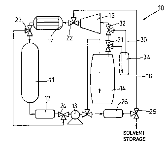
Referring now to Figure 4, there is shown a variant on the Figure 2
apparatus, that is suitable for use when the solvent includes a co-solvent
2s or entrainer, such as ethanol, whose physical properties differ
significantly from those of HFC solvents.
The Figure 4 apparatus 10 is similar to the Figure 2 apparatus, with like
reference numerals denoting like components, except that the main flow
30 loop includes an additional branch loop 30 whose function is to remove
9
WO 01/17646 CA 02383899 2002-02-28 PCT/GB00/03387
excess ethanol from the HFC solvent by washing.
Branch loop 30 is selectively switchably connectable, by means of flow
control valves 31 and 32 (that may be similar to the other flow control
s valves in the apparatus 10), to form part of the main flow loop.
Branch loop 30 includes an in-line connected hollow vessel 34 in which
washing of HFC solvent vapour may take place. Vessel 34 may contain
e.g. water, through which the HFC vapour is passed under pressure e.g.
to from an optional pump. Alternatively vessel 34 may contain a hydrophilic
filter material (e.g. cellulose) moistened with water.
Branch loop 30 and vessel 34 may be located if desired at another point in
the main loop of apparatus, for example if it is desired to wash the HFC at
is a point in the circuit where it is in liquid form. In this case the vessel
34
may be of the moist hydrophilic - filter type or may be water filled, and
the ethanol (or other co-solvent/entrainer) may be removed from the liquid
HFC by decanting one liquid from the other. The vessel 34 may if
desired be removable from the apparatus 10 or at least moveable for this
2o purpose.
Figure 5 shows the washing vessel 34 incorporated into the Figure 3
apparatus. Here the vessel 34 (which may be the same as vessel 34 in
Figure 4) is operatively connected in-line between valves 23 and 23a.
2s Since in this embodiment vessel 34 treats working fluid downstream of
condenser 17, the solvent mixture is in liquid form. For this reason the
preferred construction of vessel 34 is the moistened hydrophilic type
mentioned above, although a liquid water wash (whose content will
require decanting as described above) may be used instead.
10
WO 01/17646 cA 02383899 2002-02-28 pCT/GB00/03387
Regardless of the embodiment adopted, the preferred adsorbent for the
organic contaminants is likely to be carbon-based, particularly an
activated carbon derived from either plant materials such as coconut husk
or from pyrolysis of fossil fuel materials. The desiccant may be selected
s from a range of conventional materials including silica gel, alumina and
aluminosilicate molecular sieves. There will be particular advantage in
using a combination of a molecular sieve desiccant with either silica gel or
alumina, the molecular sieve being used to polish water after gross water
removal by the bulk of the silica/alumina. The use of an alumina
to containing basic sites will also act to further reduce acidic organic
components from the solvent whilst an alumina containing acidic sites will
help to further reduce the levels of basic organic contaminants. The
preferred aluminosilicate molecular sieves are likely to have a pore size of
between 2A and 4A.
is
In use the contaminated HFC mixture may, after biomass extraction, be
passed around the relevant circuit, contacting and being acted on by each
of the purifying components in turn until adequate HFC purity results.
The apparatus 10 may then be re-used for extracting biomass.
In the Figure 4 and 5 embodiments a co-solvent/entrainer replenishment
line, for supplying fresh co-solvent/entrainer to the apparatus 10, may be
switchably connectable at a chosen location in the main flow loop. The
purpose of this is to replenish co-solvent/entrainer removed from the
circuit in vessel 34.
The amount of fresh material added may be controlled in dependence on
the quantity of co-solvent/entrainer in the evaporator 14 following
extraction. Such control may be driven by e.g. a programmed
3o microprocessor, based on transducer readings; or may be manual.
11