Language selection

Search

Patent 2383979 Summary

Third-party information liability

Some of the information on this Web page has been provided by external sources. The Government of Canada is not responsible for the accuracy, reliability or currency of the information supplied by external sources. Users wishing to rely upon this information should consult directly with the source of the information. Content provided by external sources is not subject to official languages, privacy and accessibility requirements.

Claims and Abstract availability

Any discrepancies in the text and image of the Claims and Abstract are due to differing posting times. Text of the Claims and Abstract are posted:

  • At the time the application is open to public inspection;
  • At the time of issue of the patent (grant).
(12) Patent Application: (11) CA 2383979
(54) English Title: ON-LINE FILTER MONITORING SYSTEM
(54) French Title: SYSTEME DE SURVEILLANCE EN-LIGNE DES FILTRES
Status: Deemed Abandoned and Beyond the Period of Reinstatement - Pending Response to Notice of Disregarded Communication
Bibliographic Data
(51) International Patent Classification (IPC):
  • B1D 46/46 (2006.01)
  • B1D 29/11 (2006.01)
  • B1D 37/04 (2006.01)
(72) Inventors :
  • FEWEL, KENNETH J. (United States of America)
(73) Owners :
  • PEERLESS MFG. CO.
(71) Applicants :
  • PEERLESS MFG. CO. (United States of America)
(74) Agent: KIRBY EADES GALE BAKER
(74) Associate agent:
(45) Issued:
(86) PCT Filing Date: 2000-09-13
(87) Open to Public Inspection: 2001-03-22
Availability of licence: N/A
Dedicated to the Public: N/A
(25) Language of filing: English

Patent Cooperation Treaty (PCT): Yes
(86) PCT Filing Number: PCT/US2000/025038
(87) International Publication Number: US2000025038
(85) National Entry: 2002-03-05

(30) Application Priority Data:
Application No. Country/Territory Date
09/396,915 (United States of America) 1999-09-15

Abstracts

English Abstract


A monitoring system (10) is disclosed for monitoring the condition of a filter
(16) filtering a gas or liquid. Using various sensors, the permeability of the
filter is monitored on a continuous basis. A significant increase in
permeability, decrease in permeability or rate of change of permeability can
lead to an indication of filter failure, such as rupture, leakage, loading and
unloading. The system can be monitored by a computer and monitored from a
remote location through phone lines and Internet computer systems.


French Abstract

La présente invention concerne un système de surveillance (10) servant à surveiller l'état d'un filtre (16) traitant un gaz ou un liquide. L'utilisation de diverses sondes permet de faire un suivi permanent de la perméabilité du filtre. Toute augmentation ou diminution notable de la perméabilité ou du gradient de variation de la perméabilité peut amener à la conclusion que le filtre présente un problème tel qu'une rupture, une fuite, une saturation ou une dépose. La surveillance du système peut se faire au moyen d'un ordinateur, éventuellement hors site via des lignes téléphoniques et des systèmes informatiques raccordés à l'Internet.

Claims

Note: Claims are shown in the official language in which they were submitted.

CLAIMS:
1. A monitoring system (10) for use with a filter acsemhly (14) having a
filter
(16), an inflow path (12) for a material to flow to and through the filter
(16) and an
outflow path (18) for material to flow from the filter (16), comprising:
a flow meter (20) to sense the volume flow of the material;
a differential pressure sensor (28) to sense the pressure difference between
the
inflow path (12) and outflow path (18);
a pressure sensor (36) to sense a pressure of the material;
a temperature sensor (32) to sense the temperature of the material; and
a control (24) operatively connected to the flow meter (20), differential
pressure.
sensor (28), pressure sensor (36) and temperature sensor (32) to input the
sensed volume
flow, pressure difference, pressure, and temperature to calculate the
permeability of the
filter (16).
2. The monitoring system of Claim 1 wherein the control (24) has an alarm
activated by a condition of the permeability being above a predetermined
value.
3. The monitoring system of Claim 1 wherein the control (24) has an alarm
activated by a condition of the peiincability being below a predetermined
value.
4. The monitoring system of Claim 1 wherein the control (24) has an alarm
activated by a condition of the permeability changing at a rate exceedine a
predetermined
value.
5. The monitoring system of Claim 1 wherein the control (24) is a computer.
6. The monitoring system of Claim 1 wherein the control (24) detects filter
rupture.
7. The monitoring system of Claim 1 wherein the control (24) detects filter
leakage.
7

8. The monitoring system of Claim 1 wherein the control (24) detects filter
slugging.
9. The monitoring system of Claim 1 wherein the control (24) detects filter
unloading.
10. The monitoring system of Claim 1 wherein the control (24) calculates the
time to filter changes based on permeability.
11. The monitoring system of Claim 1 wherein the control (24) determines
particle loading of the filter.
12. The monitoring system of Claim 1 further comprising a remote computer
terminal (10) in communication with said control.
13. A method for monitoring the condition of a filter (16) within a filter
assembly (14), the filter assembly (14) having an inflow path (12) for
material to flow to
and through the filter (16) and an outflow path (18) for material to flow from
the filter
(16), comprising the steps of:
measuring a material flow volume of the material through the filter (16) with
a
flow meter (20);
measuring a pressure of the flow;
measuring a pressure difference between the inflow path and the outflow path
with
a differential pressure sensor (28);
sensing a temperature of the material with a temperature system (32); and
calculating a permeability of the filter based on the sensed material volume
flow,
pressure, pressure difference and temperature.
14. The method of Claim 13 further comprising the step of activating an alarm
where a condition of permeability is above a pre-determined value, below a pre-
determined value, or changing at a rate exceeding a pre-determined value.
15. The method of Claim l3 further comprising the step of detecting a filter
rapture based on the thus calculated permeability.
8

16. The method of Claim 13 further comprising the step of detecting filter
leakage based on the thus calculated permeability.
17. The method of Claim 13 further comprising the step of detecting filter
slugging based on the thus calculated permeability.
18. The method of Claim 13 further comprising the step of detecting filter
unloading based on the thus calculated permeability.
19. The method of Claim 13 further comprising the step of calculating an
interval to filter change based on the thus calculated permeability.
20. The method of Claim 13 further comprising the step of determining particle
loading of the filter (16) based on the thus calculated permeability.
21. The method of Claim 13 further comprising the step of monitoring the
permeability by a remote computer network (40).
22. The monitoring system of Claim 1 wherein the permeability is calculated
according to a relationship between at least the volume flow of the material,
the viscosity
of the material, and the pressure difference between the inflow path (12) and
the outflow
path (18).
9

23. The monitoring system of Claim 1 wherein the permeability is calculated
by the control based upon the equation:
<IMG>
wherein:
k = the permeability of the filter (16);
Q = the volume flow of the material;
µ = viscosity of the material;
d.p. = the differential pressure;
K= inertial resistance to flow in the filter assembly (14);
p = density of the material; and
gc = gravity constant.
24. The method of Claim 13 wherein the step of calculating permeability is
carried out according to a relationship between at least the volume flow of
the material,
the viscosity of the material, and the pressure difference between the inflow
path (12) and
the outflow path (18).

25. The method of Claim 13 wherein the step of calculating the permeability of
the filter (16) is carried out according to the equation:
<IMG>
wherein:
k=the permeability of the filter (16);
Q = the volume flow of the fluid;
µ = viscosity of the fluid;
d.p. = the differential pressure;
K= inertial resistance to flow in the filter assembly (14);
p= density of the fluid; and
gc = gravity constant.
11

Description

Note: Descriptions are shown in the official language in which they were submitted.


CA 02383979 2002-03-05
WO 01/19495 PCT/US00/25038
ON-LINE FILTER MONITORING SYSTEM
TECHNICAL FIELD OF THE INVENTION
This invention relates to continuous monitoring of the condition of a filter.
BACKGROUND OF THE INVENTION
Filters are utilized in a wide variety of applications. Many industrial
applications
require the filtering of process gases, for example.
One concern that has always existed in a filtering environment is the desire
to
know the condition of the filter to ensure that it is performing its filtering
task. Filters can
become loaded or plugged and no longer permit effective filtering. Filters can
also rupture
and leak, permitting unfiltered material to pass through or around the filter.
A need exists
for a system of monitoring the condition of the filter.
SUMMARY OF THE INVENTION
In accordance with one aspect of the present invention, a monitoring system is
provided for use with a filter assembly having a filter, an inflow path for a
material to flow
to the filter and an outflow path for material to flow from the filter. The
monitoring
system includes a flow meter to sense volume flow, a differential pressure
sensor to sense
the pressure difference in the inflow path and the outflow path, a pressure
sensor for the
flow and a temperature sensor to sense the temperature of the flow. A computer
takes
input from the flow meter, differential pressure sensor and temperature sensor
to calculate
the permeability of the filter. This provides an indication of filtering
effectiveness.

CA 02383979 2002-03-05
WO 01/19495 PCT/US00/25038
In accordance with another aspect of the present invention, the monitoring
system
computer has an alarm which is activated by a condition of the permeability
being above a
predetermined value, below a predetermined value or changing at a rate
exceeding a
predetermined value. In accordance with another aspect of the present
invention, the
control is a computer that allows remote monitoring and control of the system.
BRIEF DESCRIPTION OF THE DRAWING
For a more complete understanding of the present invention and for further
advantages thereof, reference is now made to the following Detailed
Description, taken in
conjunction with the following drawing:
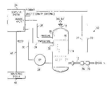
FIGURE 1 is a view of a monitoring system forming a first embodiment of the
present invention.
DETAILED DESCRIPTION OF THE INVENTION
With reference to FIGURE 1, a first embodiment of the present invention will
be
described. The invention is a monitoring system 10 whereby permeability of a
filter can
be computed and monitored continuously by a computer programmed to interpret
the
changes in permeability over time.
A gas or liquid to be filtered flows in an inlet line 12 to a filter vessel 14
which
contains the filter 16 therein. The gas or liquid being filtered passes
through filter 16 and
is filtered thereby and is subsequently transported from the filter vessel
through an outlet
line 18. A flow meter 20 is placed in the inlet line 12 to measure the flow
rate of the input
gas or liquid. This flow rate is communicated through a signal line 22 to a
computer
system 24. An optional on-line analyzer 26 also is placed in the inlet line 12
which sends
composition data to the computer system 24 for calculation of specific gravity
through a
signal line 27. A differential pressure transmitter 28 senses the pressure
upstream of and
downstream of the filter 16. A signal line 30 connects the differential
pressure transmitter
28 to the computer system 24.
2

CA 02383979 2002-03-05
WO 01/19495 PCT/US00/25038
A temperature transmitter 32 senses the temperature of the gas or liquid
flowing
through the filter 16 and communicates this information through a signal line
34 to the
computer system 24. A pressure transmitter 36 measures the pressure of the gas
or liquid
and communicates this information through a signal line 38 to the computer
system 24. A
monitoring system interface 40 in the form of a recorder, video monitor, modem
or other
data transmission device is connected to the computer system 24 through a
signal line 42,
typically an RS-232 line.
The purpose of the computer system 24 is to intake the data from the various
sensors and calculate the permeability of the filter, providing information
regarding the
condition of the filter to determine rupture, leakage, loading and unloading
on a real time
basis. The permeability is the conduciveness to viscous flow. It is the
inverse of
resistance to viscous flow. In equation form:
d. p. - k ~.Q + Kp Q C
g
Where : d.p. - pressure drop
k - permeability of the filter media
- gas viscosity
Q - actual gas or liquid volume flow
K - inertial resistance to flow due to minor losses
p - density of flow
gc - gravity constant
K and k are determined from measured data.
3

V1111V~ VIivIVi v.VV~ L~lVlr VVVIiJ ~w0w~..w
13-09-2001 Attorney Docket No. 11163/12802 US0025038
CA 02383979 2002-03-05
By algebraic manipulation, the permeability can be computed continuously given
the other known variables in the form of analog or digital signals from
transmitters
attached to the filter vessel and feed line.
The equation for monitoring permeability is:
k = Q~ ~~d:P~) - ~KPD ~ ) ~~28c)
The computer system 24 will contain programmed algorithms which will compute
the permeability and calculate the moving averages, and the rate of change of
permeability
with respect to several time intervals. The algorithms will compute the
conditions of the
filter based on this data set.
For example, the time average permeability will be computed for several time
intervals and stored with time data to determine the rate of change of
permeability for
several time intervals. "If then" statements can detect if the rate of change
of permeability
is exceeding certain limits which have been determined~to indicate slugging yr
rupturing.
Also, the direction of rate of change can differentiate between loading ox
unloading. The
1 S long range steady rate of decrease in permeability can allow estimation of
ftltcr life
remaining. ,
Viscosity of the gas will bed measured by an indirect method, utilizing
temperature,
and if available, specific gravity of the gas or liquid. Table lookups or
analyical formulas
can be used to calculate viscosity. '
A number of conditions can be detected by monitoring permeability. A first .
condition is filter rupture or leakage. 1f permeability were to increase
suddenly by a
significant amount, then a break would be indicated. This could~bc dctcctcd by
the use of
a limit rate of change which wuuld'.be an indicator of rupture, if the rate of
change is
positive. y ..
Filter slugging can be detected. If permeability were to decrease suddenly by
a
significant amount, liquid slugging of the filter would be indicated. This
could be
4
Ertwf .ze t t :13/09/2001 22:52 Ermf .nr .:910 P .009
AMENDED SHEET

CA 02383979 2002-03-05
WO 01/19495 PCTlUS00/25038
determined by a negative rate of change of permeability limit. Filter slugging
could be a
result of primary separator carryover or need for a primary separator.
Filter unloading can be detected. If the rate of change in permeability
changes to a
flat or increasing level with time, then unloading would be indicated. Filter
changeout
would be urgently indicated.
The time for changeout can be monitored. This monitoring system could also be
useful in estimating the time left before filter changeout would be necessary.
Knowing the
rate of change of permeability and the level at which changeout would be
recommended
allows a calculation of the hours to changeout.
Filter loading can be measured. By measuring the rate of decrease in
permeability,
the effective loading of solid particulate can be estimated. Also, the level
of permeability
would indicate liquid loading in liquid coalescing service.
As noted, the monitoring system 40 can be a modem. This permits the computer
system 24 to be connected with a remote terminal hooked to a phone system
which allows
sending of the data regarding permeability in serial form over phone lines and
through the
Internet computer system worldwide web, if desired. Thus, the actual computer
system 24
can be remotely located from the filter 16. Thus, the filter conditions or a
number of
filters could be monitored and controlled remotely from a single location from
any
geographical position which has adequate communication to the computer system
24.
Previous designs include the use of a pressure differential gauge to monitor
filter
life. This is not always adequate due to the very significant inertial losses
that are present
in pressurized service. The inertial losses due to expansion, contraction, and
bends are
large enough in pressurized service to make the viscous filter losses
relatively insignificant
and undetectable with a filter differential pressure gauge. By separating and
subtracting
out the known inertial losses, the viscous filter loss is known very
accurately and can be
monitored over time to determine the above conditions.
5

CA 02383979 2002-03-05
WO 01/19495 PCT/US00/25038
Whereas the present invention has been described with respect to a specific
embodiment thereof, it will be understood that various changes and
modifications will be
suggested to one skilled in the art and it is intended to encompass such
changes and
modifications as fall within the scope of the appended claims.
6

Representative Drawing
A single figure which represents the drawing illustrating the invention.
Administrative Status

2024-08-01:As part of the Next Generation Patents (NGP) transition, the Canadian Patents Database (CPD) now contains a more detailed Event History, which replicates the Event Log of our new back-office solution.

Please note that "Inactive:" events refers to events no longer in use in our new back-office solution.

For a clearer understanding of the status of the application/patent presented on this page, the site Disclaimer , as well as the definitions for Patent , Event History , Maintenance Fee  and Payment History  should be consulted.

Event History

Description Date
Inactive: IPC from MCD 2006-03-12
Application Not Reinstated by Deadline 2004-09-13
Time Limit for Reversal Expired 2004-09-13
Deemed Abandoned - Failure to Respond to Maintenance Fee Notice 2003-09-15
Letter Sent 2002-11-04
Inactive: Single transfer 2002-09-17
Inactive: Cover page published 2002-09-04
Inactive: Courtesy letter - Evidence 2002-09-03
Inactive: Notice - National entry - No RFE 2002-08-29
Application Received - PCT 2002-06-08
National Entry Requirements Determined Compliant 2002-03-05
Application Published (Open to Public Inspection) 2001-03-22

Abandonment History

Abandonment Date Reason Reinstatement Date
2003-09-15

Maintenance Fee

The last payment was received on 2002-08-16

Note : If the full payment has not been received on or before the date indicated, a further fee may be required which may be one of the following

  • the reinstatement fee;
  • the late payment fee; or
  • additional fee to reverse deemed expiry.

Patent fees are adjusted on the 1st of January every year. The amounts above are the current amounts if received by December 31 of the current year.
Please refer to the CIPO Patent Fees web page to see all current fee amounts.

Fee History

Fee Type Anniversary Year Due Date Paid Date
Basic national fee - standard 2002-03-05
Registration of a document 2002-03-05
MF (application, 2nd anniv.) - standard 02 2002-09-13 2002-08-16
Owners on Record

Note: Records showing the ownership history in alphabetical order.

Current Owners on Record
PEERLESS MFG. CO.
Past Owners on Record
KENNETH J. FEWEL
Past Owners that do not appear in the "Owners on Record" listing will appear in other documentation within the application.
Documents

To view selected files, please enter reCAPTCHA code :


To view images, click a link in the Document Description column (Temporarily unavailable). To download the documents, select one or more checkboxes in the first column and then click the "Download Selected in PDF format (Zip Archive)" or the "Download Selected as Single PDF" button.

List of published and non-published patent-specific documents on the CPD .

If you have any difficulty accessing content, you can call the Client Service Centre at 1-866-997-1936 or send them an e-mail at CIPO Client Service Centre.


Document
Description 
Date
(yyyy-mm-dd) 
Number of pages   Size of Image (KB) 
Representative drawing 2002-09-02 1 8
Drawings 2002-03-04 1 15
Abstract 2002-03-04 1 49
Claims 2002-03-04 5 153
Description 2002-03-04 6 212
Cover Page 2002-09-03 1 37
Reminder of maintenance fee due 2002-08-28 1 109
Notice of National Entry 2002-08-28 1 192
Courtesy - Certificate of registration (related document(s)) 2002-11-03 1 109
Courtesy - Abandonment Letter (Maintenance Fee) 2003-11-09 1 176
PCT 2002-03-04 20 683
Correspondence 2002-08-28 1 24