Note: Descriptions are shown in the official language in which they were submitted.
CA 02384225 2002-04-29
00-mAE2-283
-1-
CIRCUIT BREAKER
HAVING A MOVABLE AND ILLUMINABLE ARC FAULT INDICATOR
CROSS-REFERENCE TO RELATED APPLICATIONS
This application is related to commonly assigned, concurrently filed
United States Patent Application Serial No. / , filed , 2001,
entitled "Circuit Breaker Including An Arc Fault Trip Actuator Having An
Indicator
Latch And A Trip Latch" (Attorney Docket No. 00-mAE2-284); and United States
Patent Application Serial No. / , filed , 2001, entitled
"Circuit Breaker" (Attorney Docket No. 00-mAE2-326).
This application is also related to commonly assigned, co-pending
United States Patent Application Serial No. 09/506,871, filed February 15,
2000,
entitled "Circuit Breaker With Instantaneous Trip Provided By Main Conductor
Routed Through Magnetic Circuit Of Electronic Trip Motor".
BAC'.KGROUND OF THE INVENTION
Field of the Invention
This invention relates to electrical switching apparatus and, more
particularly, to circuit breakers, such as, for example, arc fault circuit
breakers.
Background Information
Circuit breakers are used to protect electrical circuitry from damage
due to an overcurrent condition, such as an overload condition or a relatively
high
level short circuit or fault condition. In small circuit breakers, commonly
referred to
as miniature circuit breakers, used for residential and light commercial
applications,
such protection is typically provided by a thermal-magnetic trip device. This
trip
device includes a bimetal, which heats and bends in response to a persistent
overcurrent condition. The bimetal, in turn, unlatches a spring powered
operating
mechanism, which opens the separable contacts of the circuit breaker to
interrupt
current flow in the protected power system.
CA 02384225 2002-04-29
00-mAE2-283
-2-
Subminiature circuit breakers are used, for example, in aircraft
electrical systems where they not only provide overcurrent protection but also
serve as
switches for turning equipment on and off. As such, they are subjected to
heavy use
and, therefore, must be capable of performing reliably over many operating
cycles.
They also must be small to accommodate the high-density layout of circuit
breaker
panels, which make circuit breakers for numerous circuits accessible to a
user.
Aircraft electrical systems usually consist of hundreds of circuit breakers,
each of
which is used for a circuit protection function as well as a circuit
disconnection
function through a push-pull handle.
The circuit breaker push-pull handle is moved from in-to-out in order
to open the load circuit. This action may be either manual or, else, automatic
in the
event of an overload or fault condition. If the push-pull handle is moved from
out-to-
in, then the load circuit is re-energized. If the load circuit had been
automatically de-
energized, then the out-to-in operation of the push-pull handle corresponds to
a circuit
breaker reset action.
Typically, subminiature circuit breakers have only provided protection
against persistent overcurrents implemented by a latch triggered by a bimetal
responsive to IZR heating resulting from the overcurrent. There is a growing
interest
in providing additional protection, and most importantly arc fault protection.
Arc
faults are typically high impedance faults and can be intermittent.
Nevertheless, such
arc faults can result in a fire.
Although many circuit breakers also employ ground fault protection, in
aircraft applications, the aircraft frame is ground, and there is no neutral
conductor.
Some aircraft systems have also provided ground fault protection, but through
the use
of additional devices, namely current transformers which in some cases are
remotely
located from the protective relay.
During sporadic arcing fault conditions, the overload capability of the
circuit breaker will not function since the root-mean-squared (RMS) value of
the fault
current is too small to activate the automatic trip circuit. The addition of
electronic
arc fault sensing to a circuit breaker can add one of the elements required
for
CA 02384225 2002-04-29
00-mAE2-283
-3-
sputtering arc fault protection - ideally, the output of an electronic arc
fault sensing
circuit directly trips and, thus, opens the circuit breaker. It is still
desirable, however,
to provide separate indications in order to distinguish an arc fault trip from
an
overcurrent-induced trip.
Finally, there is an interest in providing an instantaneous trip in
response to very high overcurrents such as would be drawn by a short circuit.
The challenge is to provide alternative protection and separate
indications in a very small package, which will operate reliably with heavy
use over a
prolonged period. A device which meets all the above criteria and can be
automatically assembled is desirable.
In aircraft applications, two practical considerations make automatic
operation difficult to achieve and, possibly, undesirable. First, the design
of a
conventional aircraft circuit breaker makes it difficult to add an externally
initiated
tripping circuit thereto. Second, certain circuits on an aircraft are so
critical that
manual intervention by a crewmember may be desirable before a circuit is de-
energized.
U.S. Patent No. x,546,266 discloses a circuit interrupter including
ground fault and arcing fault trip circuits, and indicators, such as LEDs, to
produce an
indication of the cause of the trip.
U.S. Patent No. 5,831,500 discloses a circuit breaker employing a trip
flag, a status insert and a status flag that are viewable through a lens based
upon the
trip, open, and closed positions, respectively, of the circuit breaker.
U.S. Patent No. 5,847,913 discloses a circuit breaker employing
ground fault interruption and arc fault detecting circuitry. Conduits are
provided in
the circuit breaker housing for conveying light or reflecting light between
light
sources, plungers or bimetal disks and an opening of the housing.
U.S. Patent No. 6,084,756 discloses a tester for an arc fault circuit
breaker in which an indicator is extinguished when a circuit breaker responds
to an
arc fault condition.
There is room for improvement in circuit breakers.
CA 02384225 2002-04-29
00-mAE2-283
_4_
SUMMARY OF THE INVENTION
The present invention is directed to a circuit breaker including an arc
fault annunciator. In the event that an arc fault is detected, the annunciator
provides a
visual indication that an arc fault exists. The visual indication allows
identification of
the associated circuit breaker that is protecting the arc faulted circuit. In
aircraft
applications, for example, the aircraft crew can make a decision as to whether
or not
the circuit should be re-energized or left de-energized. The visual indication
may
serve as a reminder to perform subsequent aircraft maintenance.
As one aspect of the invention, an aircraft circuit breaker comprises: a
housing; separable contacts mounted in the housing; a latchable operating
mechanism
including a latch member which when unlatched opens the separable contacts; an
overcurrent assembly responsive to selected conditions of current flowing
through the
separable contacts for unlatching the latch member to trip the separable
contacts open;
1 S a movable and illuminable arc fault indicator having a first portion and a
second
portion internal to the housing; an arc fault actuator which when energized
moves the
second portion of the movable and illuminable arc fault indicator; and an arc
fault
current assembly responsive t:o selected arc fault conditions of current
flowing
through the separable contacts for energizing the arc fault actuator to move
the second
portion of the movable and illuminable arc fault indicator internal to the
housing and
the first portion of the movable and illuminable arc fault indicator external
to the
housing, the arc fault current assembly including a light for illuminating the
first
portion of the movable and illuminable arc fault indicator.
Preferably, the movable and illuminable arc fault indicator further has
a spring, which engages the second portion of the movable and illuminable arc
fault
indicator, and the arc fault actuator includes a latch, which when moved,
allows the
spring to move the second portion. The first portion of the movable and
illuminable
arc fault indicator protrudes through an opening of the housing, and the
latch, when
moved, allows the spring to move the second portion of the movable and
illuminable
arc fault indicator and, thereby, move the first portion external to the
housing.
CA 02384225 2002-04-29
00-mAE2-283
-5-
Preferably, the latchable operating mechanism includes an operating
handle, which protrudes through the opening of the housing. The first portion
of the
movable and illuminable arc fault indicator includes a ring surrounding the
operating
handle. The latch, when moved, allov~rs the spring to move the ring away from
the
opening of the housing.
The second portion of the movable and illuminable arc fault indicator
may include a light pipe having an end, which is normally proximate the light,
with
the light pipe being normally illuminated by the light; and the latch, when
moved,
allows the spring to move the movable and illuminable arc fault indicator,
thereby
moving the end of the light pipe away from the light.
As another aspect of the invention, an aircraft circuit breaker
comprises: a housing; separable contacts mounted in the housing; a latchable
operating mechanism including a latch member which when unlatched opens the
separable contacts; an overcurrent assembly responsive to selected conditions
of
current flowing through the separable contacts for unlatching the latch member
to trip
the separable contacts open; a movable and illuminable arc fault indicator
having a
first portion and a second portion internal to the housing; an arc fault trip
actuator
which when energized moves the second portion of the movable and illuminable
arc
fault indicator and unlatches the latch member to trip open the separable
contacts; an
arc fault current assembly responsive to selected arc fault conditions of
current
flowing through the separable contacts for energizing the arc fault trip
actuator to
move the second portion of the movable and illuminable arc fault indicator
internal to
the housing and the first portion of the movable and illuminable arc fault
indicator
external to the housing, and to trip open the separable contacts; and a light
for
illuminating the first portion of the movable and illuminable arc fault
indicator.
As a further aspect of the invention, a circuit breaker comprises: a
housing; separable contacts mounted in the housing; a latchable operating
mechanism
including a latch member which when unlatched opens the separable contacts; an
overcurrent assembly responsive to selected conditions of current flowing
through the
separable contacts for unlatching the latch member to trip the separable
contacts open;
CA 02384225 2002-04-29
00-mAE2-283
a movable and illuminable arc fault indicator having a first portion and a
second
portion internal to the housing; an arc fault actuator which when energized
moves the
second portion of the movable and illuminable arc fault indicator; an arc
fault current
assembly responsive to selected arc fault conditions of current flowing
through the
separable contacts for energizing the arc fault actuator to move the second
portion of
the movable and illuminable arc fault indicator internal to the housing; and
the first
portion of the movable and illuminable arc fault indicator external to the
housing; and
a light for illuminating the first portion of the movable and illuminable arc
fault
indicator.
As a preferred practice, the ring is illuminated whenever the arc fault
trip circuit is powered and the circuit breaker is not in the arc fault trip
state.
BRIEF DESCRIPTION OF THE DRAWINGS
A full understanding of the invention can be gained from the following
description of the preferred embodiments when read in conjunction with the
accompanying drawings in which:
Figure 1 is an exploded isometric view of a circuit breaker in
accordance with the present invention.
Figure 2 is another exploded isometric view from the opposite end of
Figure 1.
Figure 3 is a front elevation view of the circuit breaker of Figure 1,
with one-half of the cover and two top plates removed, showing the circuit
breaker in
the off condition.
Figure 4 is a view similar to Figure 3 but showing the circuit breaker in
the on condition.
Figure 5 is a view similar to Figure 3 but showing the circuit breaker in
the tripped condition.
Figure 6 is an exploded isometric view of the operating mechanism
and two top plates of the circuit breaker of Figure 1.
CA 02384225 2002-04-29
00-mAE2-283
Figure 7 is an isometric view of the load terminal, bimetal, mechanism
plate, movable contact arm and line terminal of the circuit breaker of Figure
1.
Figure 8 is an isometric: view of the operating mechanism and bonnet
of the circuit breaker of Figure 1.
Figure 9 is a partially exploded isometric view of the molded case and
bonnet of the circuit breaker of Figure 1 showing z-axis assembly of the
bonnet.
Figure 10 is an exploded isometric view of two parts of the handle
assembly of the circuit breaker of Figure 1.
Figure 11 is an isometric view of the assembled handle assembly of
Figure 10.
Figure 12 is an isometric view of the trip motor, dual latch trip actuator
and bimetal of the circuit breaker of Figure 1.
Figure 13 is are exploded isometric view of the trip motor of Figure 12.
Figure 14 an isometric view of the dual trip, dual latch trip actuator of
the circuit breaker of Figure 1 in the latched position.
Figure 15 is a view similar to Figure 14 but showing the dual trip, dual
latch trip actuator in the unlatched position.
Figure 16 is an isometric view of the operating handle assembly, the
trip actuator and the arc fault indicator assembly of the circuit breaker of
Figure 1,
with the cover and some internal portions thereof not shown for clarity.
Figure 17 is an isometric view of the arc fault indicator of Figure 16.
Figure 18 is an isometric view of the circuit breaker of Figure 1 with
the handle in the trip position and the arc fault indicator assembly in the
arc fault trip
position.
Figure 19 is a view similar to Figure 18 but showing the handle and the
arc fault indicator assembly in the normal positions.
Figure 20 is a front elevation view of the combined light pipe trip
indicator ring and trip actuator of the circuit breaker of Figure 1 in the
latched
position.
CA 02384225 2002-04-29
00-mAE2-283
_g_
Figure 21 an isometric view of the indicator ring and trip actuator of
Figure 20.
Figure 22 is a view similar to Figure 21 but showing the indicator ring
and the trip actuator in the unlatched position.
Figures 23 and 24 show other circuit breakers including housings in
accordance with alternative embodiments of the invention.
DESCRIPTION OF THE PREFERRED EMBODIMENTS
The invention will be described as applied to a subminiature circuit
breaker for use in aircraft alternating current (AC) systems, which are
typically 400
Hz, but can also be used in direct current (DC) systems. It will also become
evident
that the invention is applicable to other types of circuit breakers including
those used
in AC systems operating at other frequencies; to larger circuit breakers, such
as
miniature residential or commercial circuit breakers; and to a wide range of
circuit
breaker applications, such as, for example, residential, commercial,
industrial,
aerospace, and automotive. As further non-limiting examples, both AC (e.g.,
120,
220, 480-600 VAC) operation at a wide range of frequencies (e.g., 50, 60, 120,
400
Hz) and DC operation (e.g., 42 VDC) are possible.
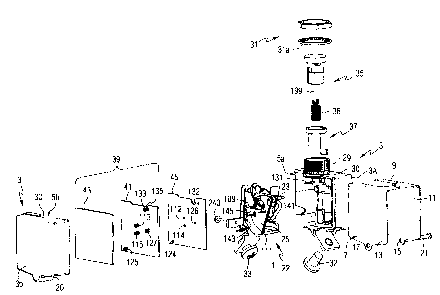
Referring to F figures 1 and 2, an exemplary circuit breaker 1 has a
housing 3 formed by first and second sections 3a and 3b molded of an
insulative resin
which sections are joined along a mating plane to form an enclosure from
confronting
cavities Sa and Sb, respectively. The circuit breaker 1 also includes an
external clip
plate 7 having a top 9 and two sides 11,13 disposed therefrom. The clip plate
side 11
captures the section or molded case 3a and the other clip plate side 13
captures the
other section or molded cover 3b. Each of the sides 11,13 includes an opening
15,17,
respectively, proximate the bottom of the corresponding side. The molded case
3a
and the molded cover 3b each have a respective opening 19 (shown in Figure 2)
and
20 therethrough. A fastener 21, such as a rivet, is disposed through the
opening 15 of
the side 11, through the openings 19,20 of the molded case 3a and the molded
cover
3b, and through the opening 17 of the side 13, in order to draw the one side
11 toward
CA 02384225 2002-04-29
00-mAE2-283
-9-
the other side 13 and, thereby, secure the molded case 3a to the molded cover
3b (as
best shown in Figure 19).
The circuit breaker 1 further includes an operating mechanism 22
mounted on a support mechanism such as the exemplary mechanism jig plate 23
(as
best shown in Figures 4 and ~'), a first mechanism top plate 24, a second
mechanism
top plate 25 (the top plates 24,25 are best shown in Figure 6), and a bezel 29
mounted
in an opening 30 of the housing 3. The bezel 29 is held in place by the
external clip
plate 7 and housing 3. In turn, a suitable fastener, such as the exemplary nut
31 and
washer 31 a mount the circuit breaker l to a mounting panel (not shown). The
circuit
breaker 1 also includes a line terminal 32, a load terminal 33, and an
operating handle
assembly 35, which protrudes through the opening 30 and the bezel 29. The
operating
handle assembly 35 is suitably biased away from the opening 30 by a spring 36.
For
ON/OFF operation, the handle assembly 35 is driven up by springs 63 and 36.
Spring
36 is employed on trip operations to reset the handle assembly 35 to the OFF
position.
The circuit breaker 1 further includes a movable and illuminable arc
fault indicator 37, an arc fault detector 39 including exemplary printed
circuit boards
(PCBs) 41,43, and an insulator 45. Suitable arc fault detectors are disclosed,
for
instance, in U.S. Patent No. 5,224,006, with a preferred type described in
U.S. Patent
No. 5,691,869, which are hereby incorporated by reference. In the exemplary
embodiment, the mechanism plate 23 is electrically conductive and is
preferably made
of stainless steel or brass. The operating mechanism 22 is assembled to and
supported
by the mechanism plate 23, which is mounted in the cavity 5a of the molded
section
3a, and the PCBs 41,43 are mounted in the cavity Sb of the molded section 3b.
Referring to Figures 3-5, the functional components of the circuit
breaker 1 include a separable contact assembly 47 (as best shown in Figures 4
and 5),
a toggle mechanism 49, the handle assembly 35, a latch member assembly 51, and
an
overcurrent assembly 53. The toggle mechanism 49, handle assembly 35, and
latch
assembly 51 form the latchable operating mechanism 22. The circuit breaker 1
also
includes the line terminal 32 and the load terminal 33 supported in the bottom
of the
CA 02384225 2002-04-29
00-mAE2-283
- 10-
molded case 3a and having cantilevered sections extending outside of the case
3 for
connection to respective line and load conductors (not shown).
As discussed below in connection with Figure 12, the overcurrent
assembly 53 includes a trip motor 119 (for arc fault conditions), and a
bimetal 129
(for persistent overcurrent conditions), The overcurrent assembly 53 also
includes an
instantaneous trip function, ufhich like the trip motor 119 and bimetal 129,
actuate the
latch assembly 51 to trip open the separable contact assembly 47.
The separable contact assembly 47 includes a fixed contact 55 fixed to
the line terminal 32 and a moveable contact 57 carried by and electrically
connected
to a movable contact arm 58 within the housing 3. The fixed contact 55 and
moveable contact 57 together form a set of separable contacts 59. The contact
arm 58
is pivotally mounted on a metal pin 61, which is part of mechanism plate 23.
The
plates 24,25 (Figure 6) retain the contact arm 58 on the pin 61. A cantilever
leaf
spring 63 forms a main spring, which biases the contact arm 58 counter-
clockwise
(with respect to Figures 3-5) to open the separable contacts 59 (as shown in
Figure 5).
As discussed below in comlection with Figure 7, the load terminal 33 is
electrically
interconnected with the contact arm 58 and the moveable contact 57, and the
line
terminal 32 is electrically connected to the fixed contact 55. The latchable
operating
mechanism 22 functions to open (Figures 3 and 5) and close (Figure 4) the
separable
contacts 59.
The contact arm 58 is pivoted between open (Figure 3) and closed
(Figure 4) positions of the separable contacts 59 by the toggle mechanism 49.
This
toggle mechanism 49 includes a lower toggle link 65 pivotally connected by a
pin 66
(shown in hidden line drawing in Figure 3) at a first or lower end 67 to the
contact
arm 58 at a pivot point 69. In this manner, the toggle mechanism 49 is
mechanically
coupled to the separable contacts 59 for opening and closing such separable
contacts.
A second toggle link 71 is pivotally connected at a first or upper end
73 by a pin 75 to a latch lever 77, which in turn is pivotally mounted by a
metal pin
79 that is part of mechanism plate 23. The second ends of the first toggle
link 65 and
the second toggle link 71 are pivotally connected by a knee pin 81. The toggle
CA 02384225 2002-04-29
00-mAE2-283
mechanism 49 further includes a drive link 83, which mechanically couples the
toggle
mechanism 49 to the handle assembly 35.
Whenever the latch assembly 51 is actuated, the latch lever 77 is
unlatched and the main spring 63 drives the movable contact arm 58 upward in
order
to open the separable contacts 59. Also, through movement of the links 65, 71,
the
latch lever 77 is rotated clockwise (with respect to Figure 5). From this
tripped
position, the spring 36 (Figures 1 and 2) returns the handle assembly 35 to
the OFF
position, and the latch lever return spring 85 returns the latch lever 77, in
order that it
can be engaged by the latch member assembly 51. Otherwise, the latch assembly
51
latches the latch lever 77 and the toggle mechanism 49 in a latched condition
(Figures
3 and 4) in which the toggle mechanism 49 is manually operable by the handle
assembly 35 between a toggle open position (Figure 3) and a toggle closed
position
(Figure 4) to open and close the separable contacts 59.
As can be seen from Figure 5, the handle assembly 35 includes a
handle member 87 having a stem 89. 'The drive link 83 of the toggle mechanism
49 is
pivotally connected to the stem 89 by a pin 91. The handle member 87 is
supported
for reciprocal linear movement by the bezel 29. The latch lever 77 has a
finger 93
terminating in a hook 95 (as best shown in Figures 14 and 15), which engages
(Figures 3 and 4) an opening 97 in the latch assembly 51.
The exemplary circuit breaker 1 operates in the following manner. In
the OFF position (Figure 3), which is the toggle open position of the toggle
mechanism 49, the handle member 87 is up with an indicator portion 99 of the
stem
89 visible to indicate the OFF' condition. The latch lever 77 is latched by
engagement
of its hook 95 by the opening 97 in the latch assembly 51. The main spring 63
has
rotated the movable contact arm 58 counter-clockwise (with respect to Figure
3)
against a stop portion 101 of the mechanism plate 23 so that the separable
contacts 59
are open.
Depressing the handle member 87, which moves linearly downward to
the position shown in Figure 4, turns ON the circuit breaker 1. The drive link
83
pushes the knee pin 81 downward and to the right, and the first toggle link 65
CA 02384225 2002-04-29
00-mAE2-283
- 12-
downward, which results in clockwise rotation (with respect to Figures 3 and
4) of the
movable contact arm 58 against the main spring 63. As the upper end of the
second
(upper) toggle link 71 is held stationary by the latch lever 77, the toggle
mechanism
49 in general, and the first (lower) link 65 in particular, seats against a
stop portion
103 of the mechanism plate 23 in the toggle closed position shown in Figure 4.
This
latter motion occurs through clockwise rotation (with respect to Figure 4) of
the
contact arm 58, which is pivotally mounted on the pin 61 at the slotted
aperture 105
thereof. With the separable contacts 59 closed in this manner, the main spring
63
provides contact pressure on the separable contacts 59 and accommodates for
wear.
The circuit breaker 1 may be manually opened from the ON position
(Figure 4) to the OFF position (Figure 3) by raising the handle member 87.
Initially, a
downward force is applied to the contact arm 58 through the first toggle link
65.
However, when the knee pin 81 passes through the center line between the pins
91
and 75, the toggle mechanism 49 breaks and the main spring 63 rotates the
movable
contact arm 58 counter-clockwise (with respect to Figures 3 and 4) until it
seats
against the stop 101 with the separable contacts 59 open. In turn, the handle
87 rises
to the OFF position (Figure 3).
As discussed below in connection with Figures 7 and 12 (persistent
overcurrent conditions), Figures 13-15 (arc fault conditions), and Figures 3-6
(instantaneous trip conditions), the circuit breaker 1 can be tripped (Figure
5) to the
open condition under various conditions. Regardless of such conditions, the
latch
assembly 51 releases the latch lever 77, which is driven clockwise (with
respect to
Figures 4 and 5) about the pin 79. Also, the movable contact arm 58 is driven
counter-clockwise (with respect to Figures 4 and 5) through the main spring 63
to
open the separable contacts 59.
In this transitory trip position, the handle member 87 is down, the latch
lever 77 is rotated clockwise, and the movable contact arm 58 is in the open
position.
From this position, the handle spring 36 returns the handle member 87 to the
OFF
position and the latch lever spring 85 rotates the latch lever 77 counter-
clockwise to a
position where it can be engaged by the latch assembly 51. This is the OFF
position.
CA 02384225 2002-04-29
00-mAE2-283
-13-
The lower end of the handle spring 36 engages an inside surface (not
shown) of the bezel 29. The inside of the bezel 29 forms a cup (not shown),
with a
relatively small hole (not shown) in the center thereof. That hole is of
sufficient size,
in order to permit the relatively small end 199 of the handle 35 to pass
therethrough.
The handle spring 36 biases the handle 35 in the direction away from the bezel
29, in
order to drive the handle to the OFF position. In the ON position (Figure 4),
links
65,71 have passed straight alignment (and, thus, have passed the toggle
position), and
the main spring 63 prevents the handle 35 from opening. The forces of the main
spring 63 and the handle spring 36 are predetermined in order that the main
spring 63
prevents the handle spring 36 from opening the circuit breaker 1. If the
circuit
breaker 1 is tripped (Figure 5), then the main spring 63 drives the movable
contact
arm 58 to the stop 101, and the force of the main spring is no longer involved
in the
force balance. Hence, the handle spring 36 can then move the handle 35 to the
OFF
position. Otherwise, when the circuit breaker 1 is ON and a user pulls on the
handle
35, that force is added to the handle spring force until there is sufficient
force to
overcome the main spring force and open the circuit breaker.
Referring to Figures 1 and 6, there are five exemplary electrical
connections to the PCB 41. Additional pins (not shown) electrically
interconnect the
PCBs 41,43. Two terminals l 09,111 pass through openings 112,114 of the
insulator
45 and electrically connect mating terminals 113,115, respectively, of the PCB
41 to a
coil assembly 117 of a trip motor or electromagnet assembly 119 (e.g., a
solenoid of
Figures 12 and 13. Another two terminals 121,123 pass through openings 124,126
of
the insulator 45 and electrically connect mating terminals 125,127,
respectively, of the
PCB 41 across the series combination of a bimetal 129 and the mechanism plate
23, in
order to sense current flowing to the load terminal 33. The terminal 121 is
electrically
connected to the load terminal 33 and to one end (164 as best shown in Figure
7) of
the bimetal 129. The other terminal 123 is electrically connected to the
mechanism
plate 23, which is electrically connected to the other end (165 as best shown
in Figure
7) of the bimetal 129.
CA 02384225 2002-04-29
00-mAE2-283
-14-
The electronic circuit (not shown) of the PCBs 41,43 measures the
voltage between the terminals 125,127 and calculates the circuit breaker load
current
from the known resistance (e.g., about 5 to 100 milliohms depending on rated
current)
of the series combination of the bimetal 129 and mechanism plate 23 (i. e., I
= V/R).
In turn, the electronic circuit determines if an arc fault condition is
present and, if so,
energizes the terminals 113,115, in order to energize the coil assembly 117
and effect
an arc fault trip (as discussed below in connection with Figures 13-15). A
fifth
terminal 131 (Figures 1-5), which is electrically connected to the bezel 29,
passes
through opening 132 of the insulator 45 and is electrically connected to
mating
terminal 133 of the PCB 41, in order to provide a suitable external ground
reference
thereto. The PCBs 41,43 derive power from voltage between the terminals
123,131.
Whenever a suitable voltage is present, the PCBs 41,43 illuminate a light
emitting
diode (LED) 135 (Figure 1 ), which is employed in connection with the arc
fault
indicator 37, as shown near the bottom of the bezel 29 of Figure 3.
As shown in Figures 1 and 6, the terminals 109 and 111 pass through
corresponding openings 137 and 139, respectively, of mechanism top plates
24,25,
without electrically contacting those plates. The mechanism top plates 24,25
are held
in place by three rivet pins 141, 143 and 145 formed on the metal pin 79, the
metal
pin 61, and a metal pin 147 (as best shown in Figure 3), which holds the
bottom end
of the spring 85, respectively. In turn, the rivet pins 141,143,145 engage the
mechanism top plates 24,25 at corresponding openings 149,151,153,
respectively,
thereof. The pin 123, which is electrically connected to the mechanism plate
23,
electrically engages the top plates 24,25 at the opening 155. Another opening
157 of
the top plates 24,25 pivotally supports a pivot point 159 of the latch
assembly 51.
The exemplary top plates 24,25 have a similar, but non-identical shape,
with the first top plate 24 being cut away in some areas in order to maintain
clearance
for certain moving parts of the operating mechanism 22, and the second top
plate 25
adding thickness to the first top plate 24 and providing an L-shaped portion
160 for
the instantaneous (magnetic) trip function as discussed below in connection
with
Figures 3-6. Preferably, the plates 24,25 are initially formed from the same
die.
CA 02384225 2002-04-29
00-mAE2-283
-15-
Figure 7 shows the load terminal 33, an overcurrent assembly 161
which includes the bimetal 129, the mechanism plate 23, the movable contact
arm 58,
the separable contacts 59 and the line terminal 32 of the circuit breaker 1 of
Figure 1.
The bimetal 129 has two leg portions 162,163 and is fixed and electrically
connected
at one end or a first foot 164 to the load terminal 33. The other bimetal end
or a
second foot 165 engages and is electrically connected to the mechanism plate
23,
which, in turn, is electrically connected to the movable contact arm 58 by a
pigtail,
such as flexible braided conductor 167, which is suitably electrically
attached (e.g., by
welding) at each end. In this manner, the load current flows from the line
terminal 32
to the fixed contact 55, to the movable contact 57, to the movable contact arm
58, to
the braided conductor 167, and to the mechanism plate 23, before passing
through the
bimetal 129 and to the load terminal 33. In the exemplary embodiment, the
bimetal
129 is designed for 2.5 A rated load current, although the invention is
applicable to a
wide range of rated currents (e.g. 15 A or greater). The load current causes
IZR
heating of the bimetal 129 resulting in movement of its upper portion (with
respect to
Figure 7) to the right side of Figure 7, with all of the exemplary load
current flowing
through the bimetal 129. A 15 A bimetal, for example, is U-shaped, and has
almost
three times the cross section of the exemplary bimetal 129, and can carry more
current
without fusing.
The exemplary bimetal 129 includes an intermediate U-shaped section
169, which is electrically connected in series between the first leg 162 and
the first
foot 164 and the second leg 163 and the second foot 165. As discussed below in
connection with Figure 12, the bimetal 129 deflects in response to selected
conditions
of load current flowing through the separable contacts 59 to actuate the latch
assembly 51. Hence, the bimetal 129 is responsive to selected conditions
(e.g.,
overload, fault current conditions) of such load current and actuates the
operating
mechanism 22 through the trip latch 229 (Figure 12) in order to trip open the
separable contacts 59.
The exemplary mechanism plate 23 provides improved support for the
bimetal 129 since the second foot 165 of the bimetal 129 is attached to the
plate 23.
CA 02384225 2002-04-29
00-mAE2-283
-16-
This provides improved routing of current through the bimetal 129 from the
separable
contacts 59, to the movable contact arm 58, to the conductor 167, to the plate
23, and
to the bimetal foot 165, which is attached to the plate 23. Furthermore, this
provides a
simpler routing of the conductor 167 (i. e., from the plate 23 to the movable
contact
arm 58), rather than from the bimetal foot 165 or leg 163 to the movable
contact arm
58).
Referring to Figures 8 and 9, a bonnet assembly 171 for the separable
contacts 59 of Figure 4 is shown. The bonnet assembly 171 includes two metal
(e.g.
made of steel) pieces 173,175, each having an L-shape, of which the first
piece 173
forms a first leg 177 of the assembly 171, and the second piece 175 forms a
second
leg 179 and a base 181 of the assembly 171, in order to form a U-shape, which
surrounds the separable contacts 59 and which cools and splits an arc when the
operating mechanism 22 trips open the separable contacts 59. The molded case
3a
(Figure 9) includes two slots 183,185 therein. The exemplary first piece 173
has a tab
189, which engages the slot 183. The exemplary second piece 175 has two
exemplary
tabs 191,193, which engage the slot 185 of the molded case 3a. Although the
exemplary bonnet assembly 171 has a generally rectangular U-shape, the
invention is
applicable to bonnet assemblies having a rectangular or a rounded U-shape.
The exemplary U-shape (as best shown in Figure 8), as formed by the
bonnet assembly 171, has the first leg 177 formed by the first L-shaped piece
173, the
base 181 formed by the second L-shaped piece 175, and the second leg 179
formed by
the second L-shaped piece 175. The second L-shaped piece 175 has a notch 195
between the two tabs 191,193 thereof. The first L-shaped piece 173 has an end
197,
which rests in the notch 195 between the tabs 191,193 of the second L-shaped
piece
175. The other end of the first L-shaped piece 173 has the tab 189, which
engages the
slot 183. The tabs 189 and 191,193 of the respective first and second L-shaped
pieces
173 and 175 mount the bonnet assembly 171 to the molded case 3a and, thus,
advantageously permit z-axis assembly of that assembly 171, with the initial
insertion
of the first L-shaped piece 173 being followed by subsequent insertion of the
second
L-shaped piece 175.
CA 02384225 2002-04-29
00-mAE2-283
-17-
Figures 10 and 11 show the handle assembly 35 of the circuit breaker 1
of Figure 1. 'the handle assembly 35 includes a first piece or stem portion
199, and a
second piece or cap portion 201. In the exemplary embodiment, the stem portion
199
is made of molded plastic having a light (e.g., white) color, and the cap
portion 201 is
made of molded plastic having a dark (e.g., black) color. As shown in Figure
11, the
stem portion 199 is secured to the cap portion 201, with the stem portion 199
providing a first visual impression and the cap portion 201 providing a
different
second visual impression.
As shown in Figure 4, the stem portion 199 is internal to the cavity 3a
of the housing 3 (Figure 1 ) when the separable contacts 59 are closed, and
the cap
portion 201 is external to the housing 3, thereby providing a first visual
impression
(e.g., the dark color of the cap portion 201 ) in the handle ON position.
Otherwise, as
shown in Figures 3 and 5, the indicator portion 99 of the stem portion 199 of
the
handle assembly 35 is external to the housing 3 when the separable contacts 59
are
open (i.e., OFF, tripped openj. As shown in Figure 10, the stem portion 199
has a
stem 203 with two ears or protrusions 205,207 at each side of the upper (with
respect
to Figure 10) end thereof. The cap portion 201 has an open end 209 and an
annular
wall 211 with two openings 213,215 therein. The annular wall 211 also has two
channels 217,219 therein, which channels are offset from the two openings
213,215,
respectively. When the handle assembly 35 is assembled, the stem 203 of the
stem
portion 199 is inserted into the open end 209 of the cap portion 201, with the
ears
205,207 being in the channels 217,219 of the annular wall 211. Then, the cap
portion
201 is rotated clockwise (with respect to Figure 10) by an exemplary one-
quarter turn,
in order to engage the ears 205,207 in the openings 213,215, respectively,
thereby
locking the two portions 199,201 together as shown in Figure 11. In this
manner, the
handle assembly 35 provides two-piece snap together construction and does not
rotate
apart. Hence, this provides an operating handle or button with sufficient
strength and,
also, provides a clear indication through the distinctly different visual
impressions of
the two molded portions 199,201, in order to show breaker status (i.e.,
OFF/tripped
versus ON).
CA 02384225 2002-04-29
-18-
00-mAE2-283
Although the exemplary embodiment employs different colors in order
to provide distinct different visual impressions of the two portions 199,201,
the
invention is applicable to a wide range of such portions that provide
distinctly
different visual impressions by, for example, distinct textures (e.g., smooth
vs. rough),
distinct patterns (e.g., a lined vs. a checked pattern, striped vs. solid),
and/or distinct
combinations thereof (e.g., a solid blue color vs. a striped pattern).
Although a two-
piece handle assembly 35 is shown, the invention is applicable to single- and
plural-
piece operating handles which preferably include distinct visual impressions
in order
to show breaker status.
The stem portion 199 is preferably molded to include a metal (e.g.
made of stainless steel) insert 221 having an opening 223 to receive the pin
91 of
Figure 4.
Figures 12 shows the overcurrent assembly 53 including the trip motor
or electromagnet assembly 119 and the bimetal 129. A cantilevered ambient
compensation bimetal 225 is operatively associated with the bimetal 129. One
end
227 of this ambient compensation bimetal 225 is suitably fixed to a trip latch
member
229 of the latch assembly 51, such as by spot welding. The cantilevered
ambient
compensation bimetal 225 extends upward (with respect to Figure 12) to
terminate in
a free end 231, which is adjacent to a free end 233 of the bimetal 129. Under
normal
operating conditions, there is a gap between the free end 233 of the bimetal
129 and
the free end 231 of the ambient compensation bimetal 225. When the bimetal 129
is
heated, it moves to the right (with respect to Figure 12) as shown by line
235. An
exemplary shuttle 237 made of plastic or some other suitable insulating
material has
notches 238 and 239, which engage the free ends 233 and 231 of the bimetal 129
and
the ambient compensation bimetal 225, respectively. The bimetal 129, when
heated,
moves the shuttle 237, thus, pulling on the ambient compensation bimetal 225,
which,
in turn, is attached to the trip latch 229. An increase or decrease in ambient
temperature conditions cause the free end 233 of the bimetal 129 and the free
end 231
of the ambient compensation bimetal 225 to move in the same direction and,
thereby,
maintain the appropriate gap between the two bimetal free ends 231,233, in
order to
CA 02384225 2002-04-29
00-mAE2-283
- 19-
eliminate the effects of changes in ambient temperature. Hence, the bimetal
129 and
the cantilevered ambient compensation bimetal 225 are coupled in series to the
trip
latch 229 to move the same in response to a persistent overcurrent condition
as
compensated for ambient conditions. Under overcurrent conditions, the bimetal
129,
therefore, pulls on the ambient bimetal 225, which rotates the trip latch 229
of the
latch assembly 51 clockwise (with respect to Figure 12, or counter-clockwise
with
respect to Figure 6) around the pivot point 159 (Figure 6) and releases the
latch lever
77 to trip the operating mechanism 22.
The thermal trip can be calibrated by a calibration screw 240, which
engages the molded case 3a of Figure 2 and which is threaded into a nut 241
disposed
between a lower surface 243 of the bimetal 129 and the fixed end 227 of the
ambient
compensation bimetal 225. By further threading and tightening the screw 240
into the
nut 241, the nut 241 engages the lower bimetal surface 243 and drives the
bimetal free
end 233 to the right (with respect to Figure 12) as shown by line 235.
Alternatively,
reversing the screw 240 out of the nut 241, allows the bimetal free end 233 to
return
to the left (with respect to Figure 12).
As shown in Figure 13, the trip motor assembly 119 includes a motor
base 245 made of magnetic steel, the coil assembly 117, and the terminals
109,111.
The base 245 includes an opening 247, which fixedly engages one end of the
spring
63 of Figure 3, and also includes an exemplary oval hole 249 therein, which
hole
mates with a corresponding oval protrusion feature 251 in the mechanism plate
23 of
Figure 7 for location of the motor assembly 119. In turn, the motor assembly
119 is
secured between the back wall 253 of the molded case 3a of Figure 9 and the
mechanism plate 23.
The exemplary motor coil assembly 117 has a magnetically permeable
motor core 254 which fits inside a coil sleeve (not shown) within an
electrical coil
256. The motor core 254 is connected at one end 255 to the base 245. The coil
assembly 117 is housed in a magnetically permeable motor cup 260, which
together
with the magnetically permeable core 254, form a magnetic circuit. The motor
core
254 holds the coil 256 within an opening 257 thereof. A pin or terminal holder
258
CA 02384225 2002-04-29
-20-
00-mAE2-283
projects laterally outward through a slot (not shown) in the motor cup 260 and
supports the terminals 109,111. The trip motor coil assembly 117 is energized
through the terminals 109,111 by an electronic trip circuit (e. g., arc fault,
ground
fault) provided on the PCBs 41,43 of Figure 1. In the exemplary embodiment,
only
an arc fault trip circuit is provided.
The exemplary circuit breaker 1 includes three different trip modes, all
of which employ the trip latch 229 of Figure 4 to actuate the operating
mechanism 22
and trip open the separable contacts 59: (1) overcurrent conditions (i.e.,
thermal trip)
detected by the bimetal 129 (Figures 7 and 12), which actuates the trip latch
229
through the shuttle 237 and ambient compensation bimetal 225; (2) arc fault
(and/or
ground fault) conditions detected by the PCBs 41,43, which energize the trip
motor
119 to actuate the trip latch 2:?9 (Figures 14 and 15); and (3) relatively
high current
conditions (i.e., instantaneous trip), which also attract the trip latch 229
(Figures 3-6).
As shown in Figure 12, the mechanism plate 23 has two posts 259,261,
which engage corresponding holes 263,265, respectively, within the cavity Sa
of the
molded case 3a (Figure 9). Preferably, the posts 259,261 and holes 263,265
provide
an alignment function, with the insulator 45, PCBs 41,43 and molded cover 3b,
as
secured by the clip plate 7, holding the operating mechanism 22, mechanism
plate 23
and trip motor 119 within the housing 3 of Figure 1.
Referring to Figures 14 and 15, the motor coil 256 is fixedly held by
the motor core 254 of Figure 13, with one end of the coil 256 (and, thus, one
end of
the motor core 254) facing an armature section 267 of the trip latch 229. When
the
coil assembly 117 is energized, the trip latch armature section 267 is
attracted toward
the motor core, thereby rotating the upper portion 269 right (with respect to
Figure
14) to an unlatched position. As discussed above in connection with Figure 5,
actuation of the trip latch 229 trips open the separable contacts 59. Hence,
for
protection against arc faults, the electronic trip circuit of the PCBs 41,43,
which is
responsive to selected arc fault conditions of current flowing through the
separable
contacts 59, monitors the load current (i.e., through terminals 121,123 of
Figure 6) for
characteristics of such faults, and energizes (i.e., through the terminals
109,111 of
CA 02384225 2002-04-29
00-mAE2-283
-21 -
Figure 6) the trip motor coil assembly 117. In turn, the magnetic flux
generated by
the energization of the coil assembly 117 attracts the trip latch armature
section 267
toward the motor core (as shown in Figure 15), in order to slide the hook 95
out of the
trip latch opening 97, thereby tripping the circuit breaker 1 open in the
manner
discussed above for a thermal trip.
Figure 16 shows the operating handle assembly 35 in the raised OFF
position (of Figure 3), and the movable and illuminable arc fault indicator 37
in a
raised tripped position. The indicator 37 (as best shown in Figure 17)
includes a first
leg or movable member 271 having a notch 272 near the lower end thereof. The
notch 272 is engaged by a first arm 273 of a spring 275. The spring 275 has a
central
portion 277, which is held by a pin 279 on the mechanism plate 23, and a
second arm
281, which is held between side-by-side pins 283,285 on the plate 23. The
indicator
37 of Figure 17 also includes a second leg or light pipe member 273 and an
illuminable ring portion 274, which is connected to the legs 271,273. The
illuminable
ring portion 274 is a first portion of the movable and illuminable arc fault
indicator
37, and the legs 271 and 273 are a second portion of the indicator 37, which
is
normally recessed within the bezel 29 of the housing 3 (Figures 3-5). Under
normal
operating conditions, the PCB 41 energizes the LED 135 (Figure 1) from an
internal
voltage, which is derived from the normal line-ground voltage between the
terminals
123,131 (Figures 1 and 6). The free end of the light pipe 273 is normally
proximate
the LED 135 (Figure 3) and normally receives light therefrom when the arc
fault
PCBs 41,43 are properly energized. I-Ience, the LED 135 normally illuminates
the
light pipe 273 and, thus, the illuminable ring portion 274. The illuminable
ring
portion 274 is visible in Figures 3-5, in order to indicate, when lit, proper
energization
of the arc fault PCBs 41,43.
Referring to Figures 14 and 15, the trip motor 119 also includes an
indicator latch 287, which is pivotally mounted on a pin 289 disposed on the
mechanism plate 23 of Figure 16. The indicator latch 287 includes an upper
latch
portion 291 having an opening 293 therein, and a lower armature portion 295.
The
indicator latch 287 is disposed at one end of the trip motor 119 and the trip
latch 229
CA 02384225 2002-04-29
-22-
00-mAE2-283
is disposed at the opposite end thereof: As shown in Figure 14, there is a
first gap 297
between the right (with respect to Figure 14) end of the trip motor cup 260
and the
trip latch armature 267, and there is a second gap 299 between the left (with
respect to
Figure 14) end of the cup 260 and the indicator latch armature 295. In
response to
current applied to the coil assembly 11.7, the trip motor 119 creates flux and
attracts
one of the latches 229,287 thereto, which closes a corresponding one of the
gaps
297,299, thereby lowering the reluctance of the coil assembly 117, increasing
the trip
motor flux, and attracting the other one of the latches 229,287, in order to
close the
other corresponding one of the gaps 297,299, as shown in Figure 15. For
example, it
is believed that the trip motor 119 first attracts the indicator latch 287,
which requires
less actuation force than that required by the trip latch 229, although the
invention is
applicable to trip motors which first attract a trip latch, or which
simultaneously
attract indicator and trip latches.
With the indicator latch 287 in the position of Figure 15, the end 301
of the spring leg 273 disengages from the indicator latch opening 293, and the
spring
leg 273 drives the movable member 271 upward with respect to Figure 16,
thereby
driving the indicator ring 274 upward to the arc fault trip position of
Figures 16 and
18. In that pasition, the light pipe 273 (Figure 17) is separated from the LED
135
(Figure 1). Also, power is removed to the PCBs 41,43. Hence, the illuminable
ring
portion 274 is no longer lit.
Figure 18 shows the circuit breaker 1 with the operating handle
assembly 35 in the handle trip position following an arc fault (and/or thermal
and/or
instantaneous) trip condition, and the indicator ring 274 disposed away from
the
housing 3 in the arc fault trip position following an arc fault trip
condition. Normally,
these positions result from an arc fault trip, although, as discussed below,
may,
alternatively, result from a previous arc fault nip, after which the operating
handle
assembly 35, but not the illuminable ring portion 274, was reset, followed by
a
thermal and/or instantaneous trip. The illuminable ring portion 274 protrudes
through
the opening 30 of the housing 3 of Figure l and through an opening 302 of the
bezel
CA 02384225 2002-04-29
- 23 -
00-mAE2-283
29. The ring portion 274 surrounds an upper stem portion 303 of the operating
handle
assembly 35.
An important aspect of the present invention is the capability of the
exemplary operating handle assembly 35 to operate independently from the arc
fault
indicator 37. In this manner, following any trip, the operating handle
assembly 35
may be reset to the ON position of Figure 4, without moving the arc fault
indicator 37
from the arc fault trip indicating position of Figure 18. For example, during
aircraft
operation, it may be highly advantageous during operation of a critical or
important
power system to re-energize such system through the operating handle assembly
35,
while leaving the arc fault indicator 37 in its arc fault trip indicating
position. In this
manner, the aircraft may be safely operated (e.g., the risk of not energizing
that power
system outweighs the risk of an arc fault), while leaving the arc fault
indicator 37
deployed for the subsequent attention by maintenance personnel only after the
aircraft
has safely landed. Similarly, the arc fault indicator 37 may be reset from the
arc fault
trip indicating position of Figure 18 by pressing downwardly on the
illuminable ring
portion 274, in order to reengage the spring leg end 301 with the indicator
latch
opening 293 (Figure 21), without moving the operating handle assembly 35
between
the OFF and ON positions thereof.
Figure 19 shows the normal operating condition of the circuit breaker 1
in which both the operating handle assembly 35 and the indicator ring 274 are
in the
normal positions. Also, as long as power is suitably applied to the circuit
breaker 1,
the illuminable ring portion 274 is normally lit by light from the LED 135
(Figure 1)
as energized by line-ground voltage between the terminal 123 (Figure 6), which
has
the line voltage from the line terminal 32, and the terminal 131 (Figure 4),
which has
the ground potential from the bezel 29 and/or a mounting panel (not shown)).
Thus,
the LED 135 is normally lit in the event that the arc fault PCBs 41,43 (Figure
1) are
energized and is, otherwise, not lit (e.g., power is not present; the bezel 29
is
improperly grounded).
Referring to Figures 20-22, the indicator leg 271 is engaged by the
spring 275 and is mechanically held down by the indicator latch 287 (Figures
20 and
CA 02384225 2002-04-29
-24-
00-mAE2-283
21 ). When an arc fault trip condition occurs, the indicator latch 287 is
actuated to the
position shown in Figure 22. When the indicator latch 287 is so moved, the
spring
275 is released from the indicator latch opening 293, which allows the spring
275 to
push up the indicator leg 271 internal to the housing 3 of Figure 1, thereby
moving the
indicator ring 274 away from and external to the housing 3 as shown in Figure
18, in
order to indicate an arc fault trip condition.
As shown in Figure 20, the latch return spring 107 extends through an
opening 305 of the motor base 245 (as best shown in Figure 13). The spring 107
drives the indicator latch 287 clockwise and drives the trip latch 229 counter-
clockwise (with respect to Figure 20) and, thus, drives both of the dual
latches
229,287.
Although the invention has been described in terms of a dual trip /
indicator latch formed by the exemplary trip motor 119, the trip latch 229,
and the
indicator latch 287, the invention is applicable to single and dual latch
functions
which actuate an indicator latch, in order to indicate an arc fault or ground
fault
condition, andlor which actuate a trip latch, in order to trip open separable
contacts.
The invention is further applicable to an indicator latch, which normally
engages a
movable member of an indicator, and which releases such member for movement by
a
spring.
In order to provide an instantaneous trip, the overcurrent assembly 53
of Figures 3-5 includes an arrangement for routing a current path of a main
conductor,
as formed by the bimetal 129, the mechanism plate 23, the flexible braid 167
and the
movable contact arm 58 of Figure 7, through a magnetic circuit, as formed by
the
motor frame 245 of Figure I2 and the two steel mechanism top plates 24,25 of
Figure
6. The motor frame 245 and plates 24,25 form a steel shape around this current
path.
The discontinuous electrical conduction paths of the exemplary magnetic
circuit direct
the magnetic flux to flow once through the general path of the steel shape,
thereby
forming a one-turn electro-magnet. Vfhenever load current flows in the circuit
breaker l, the steel shape magnetically attracts the steel trip latch 229. The
magnetic
coupling is such that suitably high load currents of at least a predetermined
magnitude
CA 02384225 2002-04-29
- 25 -
00-mAE2-283
(e.g., without limitation, about 300 A for a 2.5 A rated load), such as those
associated
with short circuits, are sufficient to actuate the trip latch 229, without
energizing the
trip motor coil assembly 117. If the load current is of sufficient magnitude,
then the
trip latch 229 is rotated in the counter-clockwise direction (with respect to
Figure 5),
thereby tripping the circuit breaker 1.
For example, magnetic flux flows around any current carrying
conductor and, preferably, flows in steel. Hence, the exemplary steel shape
around
the exemplary load current path concentrates and channels the magnetic flux to
flow
through the exemplary steel path. Although the magnetic flux preferably flows
in the
steel, it also crosses any gaps in such steel. Therefore, the top plates 24,25
are
preferably close to the motor frame 245, although physical connection is not
required.
When the magnetic flux crosses a gap in its path around the discontinuous
electrical
conduction paths, a force is generated toward closing that gap. Hence, since
the steel
path encompassing those conduction paths includes gaps between the motor frame
245 and the trip latch 229, and between the L-shaped portion 160 of the top
plate 25
and the trip latch 229, forces are generated toward closing those gaps and,
thus,
actuating the trip latch 229.
As shown in Figure 23, a circuit breaker 306 is similar to the circuit
breaker 1 of Figure 1, except that a fastener 307 is disposed through the
openings 17
and 15 (shown in Figure 1) of the clip plate 7, and beneath the molded case
309a and
the molded cover 309b, in order to draw the one side 11 toward the other side
13 and
to secure the molded case 309a to the molded cover 309b.
As shown in Figure 24, a circuit breaker 311 is similar to the circuit
breaker 1 of Figure 1, except that the molded case 313a and the molded cover
313b
each have channels 315a,315b, respectively. A fastener 317 is disposed through
the
openings 15,17 of the clip plate sides 11,13 and within the channels 31 Sa,31
Sb, in
order to draw the one side 11 toward the other side 13, thereby, securing the
molded
case 313a to the molded cover 313b.
The exemplary circuit breaker 1 is a simple and reliable mechanism,
which selectively provides multiple protection functions as well as serving as
an
CA 02384225 2002-04-29
00-mAE2-283
-26-
off/on switch. This arrangement also lends itself to automated assembly. The
molded
section 3a of the housing 3 is placed on a flat surface and the parts are all
inserted
from above. The mechanism plate 23, the operating mechanism 22, the handle
assembly 35, the latch assembly 51, the bimetals 129,225, and the bonnet
assembly
171, all fit into the cavity Sa in this housing section 3a. The trip motor 119
is seated
behind the mechanism plate 23, and the PCBs 41,43 are connected by electrical
pins
109,111,121,123,131. The PCBs 41,43 extend into the cavity Sb of the housing
section 3b. The sections 3a,3b, in tum, are secured together by the clip plate
7 and
fastener 21. In one embodiment, the exemplary circuit breaker 1 is about 1 to
1.2 in.
tall, about 1 in. wide, and about 0.8 in. thick.
While specific embodiments of the invention have been described in
detail, it will be appreciated by those skilled in the art that various
modifications and
alternatives to those details could be developed in light of the overall
teachings of the
disclosure. Accordingly, the particular arrangements disclosed are meant to be
illustrative only and not limiting as to the scope of invention which is to be
given the
full breadth of the claims appended and any and all equivalents thereof.