Note: Descriptions are shown in the official language in which they were submitted.
CA 02384334 2002-03-07
WO 01/20239 PCT/iJS99/20568
1
DEVICE, SYSTEM AND METHOD FOR ON-LINE EXPLOSIVE DESLAGGING
FIELD OF THE INVENTION
This disclosure relates generally to the field of boiler / furnace deslagging,
and
particularly, discloses a device, system and method allowing on-line,
explosives-based
deslagging.
BACKGROUND OF THE INVENTION
A variety of devices and methods are used to clean slag and similar deposits
from
boilers, furnaces, and similar heat exchange devices. Some of these rely on
chemicals or fluids
that interact with and erode deposits. Water cannons, steam cleaners,
pressurized air, and
similar approaches are also used. Some approaches also make use of temperature
variations.
And, of course, various types of explosive, creating strong shock waves to
blast slag deposits
off of the boiler, are also very commonly used for deslagging.
The use of explosive devices for deslagging is a particularly effective
method, as the
large shock wave from an explosion, appropriately positioned and timed, can
easily and quickly
separate large quantities of slag from the boiler surfaces. But the process is
costly, since the
boiler must be shut down (i.e. brought off line) in order to perform this type
of cleaning, and
valuable production time is thereby lost. This lost time is not only the time
during which the
cleaning process is being performed. Also lost are several hours prior to
cleaning when the
boiler must be taken off line to cool down, and several hours subsequent to
cleaning for the
2 0 boiler to be restarted and brought into full operational capacity.
Were the boiler to remain on-line during cleaning, the immense heat of the
boiler would
prematurely detonate any explosive placed into the boiler, before the
explosive has been
properly positioned for detonation, rendering the process ineffective and
possibly damaging the
boiler. Worse, loss of control over the precise timing of detonation would
create a serious
2 5 danger for personnel located near the boiler at the time of detonation.
So, to date, it has been
necessary to shut down any heat exchange device for which explosives-based
deslagging is
desired.
Several U.S. patents have been issued on various uses of explosives for
deslagging.
U.S. Patent Nos. 5,307,743 and 5,196,648 disclose, respectively, an apparatus
and method for
3 0 deslagging wherein the explosive is placed into a series of hollow,
flexible tubes, and detonated
in a timed sequence. The geometric configuration of the explosive placement,
and the timing,
CA 02384334 2002-03-07
WO 01/20239 PCT/US99/20568
are chosen to optimize the deslagging process.
2
U.S. Patent No. 5,211,135 discloses a plurality of loop clusters of detonating
cord
placed about boiler tubing panels. These are again geometrically positioned,
and detonated with
certain timed delays, to optimize effectiveness.
U.S. Patent No. 5,056,587 similarly discloses placement of explosive cord
about the
tubing panels at preselected, appropriately spaced locations, and detonation
at preselected
intervals, once again, to optimize the vibratory pattern of the tubing for
slag separation.
Each of these patents discloses certain geometric configurations for placement
of the
explosive, as well as timed, sequential detonation, so as to enhance the
deslagging process. But
in all of these disclosures, the essential problem remains. If the boiler were
to remain on-line
during deslagging, the heat of the boiler would cause the explosive to
prematurely detonate
before it is properly placed, and this uncontrolled explosion will not be
effective, may damage
the boiler, and could cause serious injury to personnel.
U.S. Patent No. 2,840,365 appears to disclose a method for introducing a tube
into "a
hot space such as an oven or a slag pocket for an oven" prior to the formation
of deposits in the
hot space; continuously feeding a coolant through the tube during the
formation of deposits in
the hot space, and, when it is time to break the deposits, inserting an
explosive into the tube
after the formation of the deposits while the tube is still somewhat cooled,
and detonating the
explosive before it has a chance to heat up and undesirably self detonate.
(See, e.g., col. 1,
lines 44-51, and claim 1) There are a number of problems with the invention
disclosed by this
patent.
First, the hot space according to this patent must be thoroughly prepared and
preconfigured, in advance, for the application of this method, and the tubes
that contain the
coolant and later the explosive, as well as the coolant feeding and discharge
system, must be in
place on a more or less permanent basis. The tubes are "inserted before the
deposits begin to
form or before they are formed sufficiently to cover the points where one
wishes to insert the
tubes" and are "cooled by the passage of a cooling fluid . . . therethrough
during operation."
(col. 2, lines 26-29 and col. 1, lines 44-51) It is necessary "to provide
sealable holes in several
bricks for allowing the tube . . . to be inserted, or . . . to remove the
bricks during operation of
3 0 the furnace so that a hole is formed through which the tube may be
inserted." (col. 2, lines 32-
36) The tubes are supported "at the back end of the pocket upon supports made
for the
purpose, e.g., by a stepped shape of the back of the wall . . . [or] at the
front end or in front of
and in the wall . . . [or by having] at least the higher tubes . . . rest
imriiediately upon the
CA 02384334 2002-03-07
WO 01/20239 PCT/US99/20568
3
deposits already formed." (col. 2, lines 49-55) A complicated series of hoses
and ducts are
attached for "feeding cooling water . . . and discharging said cooling water."
(col. 3, lines 1-
10, and FIG, 2 generally) And, the tubes must be cooled whenever the hot space
is in operation
to prevent the tubes from burning and the water from boiling. (see, e.g., col.
3 lines 14-16 and
col. 1, lines 44-51) In sum, this invention cannot simply be brought onto the
site of a hot space
after deposits have formed and then used at will to detonate the deposits
while the hot space is
still hot. Rather, the tubes must be in place and continuously cooled
essentially throughout the
entire operation of the hot space and the accumulation of deposits. And,
significant
accommodations and preparation such as tube openings and supports, the tubes
themselves, and
coolant supply and drainage infrastructure, must be permanently established
for the associated
hot space.
Second, the method disclosed by this patent is dangerous, and must be
performed
quickly to avoid danger. When the time arrives to break the slag deposits,
"the pipes . . . are
drained," various cocks, hoses, bolts and an inner pipe are loosened and
removed, and
"explosive charges are now inserted [into the pipe] . . . immediately after
termination of the
cooling so that no danger of self-detonation exists, because the explosive
charges cannot become
too hot before being exploded intentionally." (col. 3, lines 17-28) Then, the
"tubes are
exploded immediately after stopping the cooling at the end of the operation of
the furnace. . . ."
(col. 1, lines 49-51) Not only is the process of draining the pipe and
readying it to receive the
2 o explosive fairly cumbersome, it must also be done in a hurry to avoid the
danger of premature
explosion. As soon as the coolant flow is ceased, time is of the essence,
since the tubes will
begin to heat up, and the explosives must be placed into the tubes and
purposefully detonated
quickly, before the heating of the tube become so great that the explosive
accidentally self
detonates. There is nothing in this patent that discloses or suggests how to
ensure that the
2 5 explosive will not self-detonate, so that the process does not have to be
unnecessarily hurried to
avoid premature detonation.
Third, the pre-placement of the tubes as discussed above constrains the
placement of the
explosive when the time for detonation arrives. The explosives must be placed
into the tubes in
their preexisting location. There is no way to simply approach the hot space
after the slag
3 0 accumulation, freely choose any desired location within the hot space for
detonation, move an
explosive to that location in an unhurried manner, and then freely and safely
detonate the
explosive at will.
Fourth, it may be inferred from the description that there is at least some
period of time
CA 02384334 2002-03-07
WO 01/20239 PCT/US99/20568
4
during which the hot space must be taken out of operation. Certainly,
operation must cease
long enough for the site to be prepared and fitted to properly utilize the
invention as described
earlier. Since one object of the invention is to "prevent the oven . . . to be
taken out of
operation for too long a time," (col. 1, lines 39-41, emphasis added), and,
since the "tubes are
exploded immediately after stopping the cooling at the end of the operation of
the furnace or the
like" (col. 1, lines 49-51, emphasis added), it appears from this description
that the hot space is
in fact shut down for at least some time prior to detonation, and that the
crux of the invention is
to hasten the cooling of the slag body after shutdown so that detonation can
proceed more
quickly without wasting for the slag body to cool down naturally (see col. l,
lines 33-36), rather
than to allow detonation to occur while the hot space is in full operation
without any shutdown
at all.
Finally, because of all the site preparation that is needed prior to using
this invention,
and due to the configuration shown and described for placing the tubes, this
invention does not
appear to be usable across the board with any form of hot space device, but
only with a limited
type of hot space device that can be readily preconfigured to support the
disclosed horizontal
tubing structure as disclosed.
Luxemburg patent no. 41,977 has similar problems to U.S. Patent No. 2,840,365,
particularly: insofar as this patent also requires a significant amount of
site preparation and
preconfiguration before the invention disclosed thereby can be used; insofar
as one cannot
2 0 simply approach the hot space after the slag accumulation, freely choose
any desired location
within the hot space for detonation, move an explosive to that location in an
unhurried manner,
and then freely and safely detonate the explosive at will; and insofar as the
types of hot space
devices to which this patent applies also appear to be limited.
According to the invention disclosed by this patent, a "blasting hole" must be
created
2 5 within the subject hot space before the invention can be used.
(translation of page 2, second full
paragraph) Such holes are "drilled at the time of need or made prior to the
formation of the
solid mass." (translation of paragraph beginning on page 1 and ending on page
2) Since the
device for implementing the process of the invention "includes at least a tube
that permits
feeding the cooling fluid into the bottom of the blasting hole" (translation
of page 2, fourth full
3 0 paragraph) and, in one form of implementation, "a retaining plate . . .
positioned at the bottom
of the blast hole (translation of paragraph beginning on page 2 and ending on
page 3), and since
it is a key feature of the invention that the blast hole is filled with
coolant prior to and during the
insertion of the explosive, it may be inferred from this description that the
blast hole is
CA 02384334 2002-03-07
WO 01/20239 PCT/US99/20568
substantially vertical in it orientation, or at least has a significant enough
vertical component to
enable water to effectively accumulate and pool within the blast hole.
Because the subject hot space must be preconfigured with a blast hole or holes
(with
implicitly at least a substantial vertical component) before this invention
can be used, it is again
5 not possible to simply approach an unprepared hot space at will after
deposits have
accumulated, and detonate at will. Since the coolant and the explosive must be
contained within
the blast holes, it is not possible to freely move and position the explosive
wherever desired
within the hot space. The explosives can only be positioned and detonated
within the blast holes
pre-drilled for that purpose. Due to the at least partially vertical
orientation of the blast holes,
1 o the angle of approach for introducing the coolant and the explosive is
necessarily constrained.
Also, while it is not clear from the disclosure how the blast holes are
initially drilled, it appears
that at least some amount of boiler shutdown and / or disruption would be
required to introduce
these blast holes.
Finally, in both of these cited patents, the components which hold the coolant
(the tubes
for US 2,840,365 and the blast holes for LU 41,977) reside within the hot
space, and are
already very hot when the time arrives to deslag. The object of both of these
patents, is to cool
these components down before the explosive is introduced. US 2,840,365
achieves this by
virtue of the fact that the tubes are continuously cooled throughout the
operation of the hot
space, which, again, is very disruptive and requires significant preparation
of and modification
to the hot space. And LU 41,977 clearly states that "[a]ccording to all its
forms of
implementation, the device is put in place without a charge for the purpose of
cooling the blast
hole for a few hours with the injection fluid (translation of page 4, last
full paragraph, emphasis
added). It would be desirable to avoid this cooldown period altogether and
therefore save time
in the deslagging process, and to simply introduce a cooled explosive into a
hot space at will
2 5 without any need to alter or preconfigure the boiler, and to then detonate
the cooled explosive at
will once it has been properly placed in whatever detonation location is
desired. And most
certainly, the application of LU 41,977 is limited only to hot spaces into
which it is feasible to
introduce a blast hole, which appears to eliminate many types of heat~xchange
device into
which it is not feasible to introduce a blast hole.
3 0 It would be desirable if a device, system and method could be devised
which would
allow explosives to safely and controllably be used for deslagging, on-line,
without any need
to shut down the boiler during the deslagging process. By enabling a boiler or
similar heat-
exchange device to remain on-line for explosives-based deslagging, valuable
operations time for
CA 02384334 2005-03-21
WQ Ol~iOT39 PCTNS99/~Q56B
6
fixl~uni~ tx~tld d~a be secawrced.
Ic is tbaeboce desired w provide a device. sys~~ and tt~d arhe:eby explosives
may
be usad p cka<c a boiler. foe, sc~ctbbet, cx any ad~t b~ r~cbange dcvix. fuel
bt~g, a
incincraa~ device, without rcquiting tbac drvicx ua be shut down, thereby
eaabiing ~ dwice
to tataia is fbll aQeraaOn dwipg de~lag~it~.
It is deb to arable valuable apaatioas time a~ be ceoavaed, by virtue of
elbuic~ng
d>c rid for ~ of the devise nr facdiCy co be clrataed.
It ~ d~ to paaeapel safer as>a fa~:~ity ia~y. by eaabliag t#cis arrline
expl4aivesdig to ocwr is a safe sad ~ ncanaa.
is
SUMMARY OF THE INVENI'1oN
in one aspect, the present invention provides an explosive-based system for
deslagging a hot ot~li~e heat-exchange device. Ttx: system includes an
explosive device,
at least one cooling appatatus the explosive device by gas, irtsttleting of
casing
c°°~g ~~~ P'~~lY while the explosive dEavice is at any desired
location within
the hot online heat exchange device, thereby pre~renii~~g heat from the hot
online heat
exchange device from detonating the explosive device prior to a time where it
is desued
to detonate ac will the explosive device. The sys~:eirt also itccludes a
cooling apparatus
aced explosive positioning system with the cooling apparatus and the explosive
device
rnoled dtereby affixed thereto, enabling a force ~~pplied to the cooling
apparatus and
explosive positioning system tA freely move the apparatus and the explosive
device cooled thereby to any desired location within the lox online heat
exchange device
and particularly irvto a proper position for deslagging, while cooling the
explosive device_
Demnatutg means is provided for detnnatittg at will the explosive device. The
cooling
apparatus comprises at least one caalutg envelop~a in turn comprising an
insulating one
of the cooling envelopes coutprising an outer isr~ulatiug layer cvntpr;sing at
least cue
Iayer of at least orte heat insulating material insulatit~, the explosive
device from the heat
from the online heat exd>$nge device and thereby preventing Trout overheating
and so-
malirig the explosive device.
In another aspect of the invention, the cooling apparatus comprises at least
one
cooling eitvelap~e in rum cnmprisirtg a casing.
Corresponding methods for deslagging t~ hot, online heat exchange are also
provided-
CA 02384334 2005-03-21
ba
A p~efetrnd embodimetu of the iave~n eua~lc: cxplasives ea he usai far ~~aaing
slag
from a hot, an-lips boiler. furnacae, nr similar fi~I-betrni~g ar inciacradaa
dcwice, by c~livcrw~g
a hut ro the explosive which maituaias rbe oe~amue of the explosive well b~crw
what is
requited fur demm~oa. The eacplosivc, whsle it is t~:iag , is deliver w its
fired
posicioa irrsid~e the ha boiler wichnut due, a is dra dis a ao~rolled manna,
ac
tfx: ~ desirdi.
While Many abvi~xu Yariatiot~ may notur to scspe~e of crdi~ry skill iu the
reievatu
aro~, the ptaferr~i em~dia~esu discl~d beteia uses a Ear snni-perns'able
membrane
which e~k~ ibe explosive and the detaaatar c~ ar simitai device usal to the
s o a~l~~. A ~ such as ordit>arY , is detivercd at a fairly cotmatu fbw nae
inoo the iaaerior of tl~ emrclope, thereby vaoting the aaa'~aJ surface of die
exptasivc and
raai:uaiuiag gibe cxploaive well below w~er~uure. Coolant withia the a~cm6rs~
in
mrn flows our of dte mcaabrane ac a fairly ear raNC, tdrough paforati~s ac
miaascagic
aperu~res is the me~raoe. Thus cooler onolatu oomttaatly flows iuw the
membrane vvtulc
15 hover coolaru chat bas been heated by the boikx i~avs txu of the aoa~e, and
the cx~asive
is ai~od ac a, rempetxaue well below tbax uacx>ed far daaaadoa. Coola~at flow
taxes typical
of tlye ~feited embadimecu run bexwoet~ 20 snd ~tl g.~i4~s per mini.
'fbss ooolaur fbw is as the explosive is ~c berg placed its the hot bailer.
~cx the explosive has been n~vod itura the ptaper position atul its ate
maituained ac a
2 0 scow level, the acplosive ~ detot~ed as desired, tbcre#ry se~ar~ai~ the
slab from. Fund thus
c>eanlag, dte boiler.
CA 02384334 2002-03-07
WO 01/20239 PCT/US99/20568
7
coolant, such as compressed air or other non-flammable gas, in place of the
aforementioned
liquid coolant; (2) using one or more highly-heat-resistant insulating
materials to insulate the
explosive and detonator cap, in place of or in addition to the aforementioned
liquid or gaseous
coolants; and (3) preparing and using a highly-heat-resistant explosive
device, in place of or in
addition to the aforementioned liquid or gaseous coolants, and / or the
aforementioned highly-
heat-resistant insulating materials, in any desired combination.
BRIEF DESCRIPTION OF THE DRAWING
The features of the invention believed to be novel are set forth in the
appended claims.
The invention, however, together with further objects and advantages thereof,
may best be
understood by reference to the following description taken in conjunction with
the
accompanying drawings) in which:
FIG. 1 illustrates in plan view, a preferred embodiment of a device, system
and method
used to perform on-line explosive cleaning of a fuel-burning facility, using a
liquid or gaseous
coolant.
FIG. 2 illustrates in plan view, the device, system and method of FIG. 1 in
its
disassembled (preassembly) state, and is used to illustrate the method by
which this device,
system and method is assembled for use.
FIG. 3 illustrates in plan view, the use of the subject device, system and
method to
2 0 clean an on-line fuel burning or incineration facility.
FIG. 4 illustrates in plan view, an alternative preferred embodiment of this
invention,
which reduces coolant weight and enhances control over coolant flow, and which
utilizes remote
detonation.
FIG. 5 illustrates in plan view, the use of highly-heat-resistant insulating
materials to
insulate explosive device used for on-line explosive cleaning, in place of or
in addition to the
aforementioned liquid or gaseous coolants.
FIG. 6 illustrates in perspective view, a heat-resistant explosive preparation
used for on-
line explosive cleaning, in place of or in addition to the embodiments of
FIGS. 1 through 5.
3 0 DETAILED DESCRIPTION OF THE INVENTION
FIG. 1 depicts a preferred embodiment of a basic tool used for on-line
cleaning of a
fuel-burning facility such as a boiler, furnace, or similar heat exchange
device, or an
incineration device, and the discussion following outlines the associated
method for such on-line
CA 02384334 2002-03-07
WO 01/20239 PCT/US99/20568
8
cleaning.
The cleaning of the fuel burning and / or incineration facility is carried out
in the usual
manner by means of an explosive device 101, such as but not limited to an
explosive stick or
other explosive device or configuration, placed appropriately inside the
facility, and then
detonated such that the shock waves from the explosion cause slag and similar
deposits to
dislodge from the walls, tubing, etc. of the facility. This explosive device
101 is detonated by a
standard explosive detonator cap 102 or similar detonating device, which
causes controlled
detonation at the desired instant, based on a signal sent from a standard
initiator 103, by a
qualified operator.
However, to enable explosives-based cleaning to be performed on-line, i.e.,
without any
need to power down or cool down the facility, two prior art problems must be
overcome. First,
since explosives are heat-sensitive, the placement of an explosive into a hot
furnace can cause
premature, uncontrolled detonation, creating danger to both the facility and
personnel around
the explosion. Hence, it is necessary to find a way of cooling the explosive
device 101 while it
is being placed in the on-line facility and readied for detonation. Second, it
is not possible for a
person to physically enter the furnace or boiler to place the explosive, due
the immense heat of
the on-line facility. Hence, it is necessary to devise a means of placing the
explosive that can be
managed and controlled from outside the burner or furnace.
In order to properly cool explosive device 101, a cooling envelope 104 is
provided
2 0 which completely envelopes explosive device 101. During operation, in a
preferred
embodiment, cooling envelope 104 has pumped into it a coolant, such as
ordinary water, that
maintains explosive device 101 in a cooled-down state until it is ready for
detonation. Because
of the direct contact between the coolant and explosive device 101, explosive
device 101 is
ideally made of a plastic or similar waterproof housing that contains the
actual explosive powder
or other explosive material.
In an alternative preferred embodiment, air and / or gases are used instead of
a liquid
coolant. Here, it is preferred to circulate normal room temperature air
through the device.
This can be accomplished by using a standard commercial air compressor (not
shown) to
deliver and move the air past explosive device 101. Alternatively, cooled or
refrigerated air
3 0 from a portable air conditioning unit is circulated past explosive device
101, either providing
pressurization from the air conditioning unit, or using pressure provided by
an air
compressor. Also contemplated is the circulation of one or more non-flammable
gasses
such as nitrogen, or any other inert gas such as, but not limited to, carbon
dioxide,
CA 02384334 2002-03-07
WO 01/20239 PCT/US99/20568
9
halocarbon, helium, and others, past explosive device 101, similar to the
circulation of
normal air. It is to be understood that the terms "gas" or "gaseous" within
this disclosure
are intended to encompass air and any other composite gasses which, from a
chemical
standpoint, comprise a mixture of two or chemically-distinct gases.
It is important for cooling envelope 104 to provide a continuous flow of
coolant,
whether fluid or gaseous, past explosive device 101. To achieve this, cooling
envelope 104 in
the preferred embodiment is a semi-permeable membrane that allows liquid or
gaseous coolant
to flow out of it at a fairly controlled rate. It may comprise a series of
small perforations
punched into it, or can be constructed of any semi-permeable membrane material
appropriate to
its coolant-delivery function as will outlined herein. This semi-permeability
characteristic is
illustrated by the series of small dots 105 scattered throughout cooling
envelope 104 as depicted
in FIG. 1. Alternatively or in addition to permeations 105, cooling envelope
104 may
comprise a one-way fluid or gas release valve 130 to relieve the build up
within cooling
envelope 104 of fluid or gas pressure. Release valve 130 can also comprise or
be attached to
an optional recirculation conduit (not shown) enabling spent coolant to be
removed from cooling
envelope 104 and reused or recycled.
At an open end (coolant entry opening), cooling envelope 104 is attached to a
coolant
delivery pipe 106 via an envelope connector 107. As depicted here, envelope
connector 107 is
a cone-shaped apparatus permanently affixed to coolant delivery pipe 106, and
it further
2 0 comprises a standard threading 108. Cooling envelope 104 itself, at this
open end, is fitted and
permanently affixed to complementary threading (shown, but unnumbered, in FIG.
2) that is
easily screwed into and fitted with threading 108 of connector 107. While FIG.
1 depicts screw
threads in connection with a cone-shaped apparatus as the particular means of
attaching cooling
envelope 104 to coolant delivery pipe 106, any type of clamp, and indeed, many
other means of
attachment know to someone of ordinary skill would also be provide a feasible
and obvious
alternative, and such substitutions for attaching cooling envelope 104 to
coolant delivery pipe
106 are fully contemplated to be within the scope of this disclosure and its
associated claims.
Coolant delivery pipe 106, in the region where said pipe resides within
cooling envelope
104, further comprises a number of coolant delivery apertures 109, twin ring
holders 110, and
3 o an optional butt plate 111. Explosive device 101 with detonator cap 102 is
affixed to one end of
an explosive connector (broomstick) 112 with explosive-to-broomstick
attachment means 113
such as, but not limited to, duct tape, wire, rope, or any other means that
provides a secure
attachment. The other end of broomstick is slid through twin ring holders 110
until it abuts butt
CA 02384334 2002-03-07
WO 01/20239 PCT/US99/20568
plate 111, as shown. At that point, broomstick 112, optionally, may be further
secured by
means of, for example, a bolt 114 and wingnut 115 running through both
broomstick 112 and
coolant delivery pipe 106 as depicted. While rings 110, butt plate 111, and
nut and bolt 115
and 114 provide one way to secure broomstick 112 to coolant delivery pipe 106,
many other
5 ways to secure broomstick 112 to coolant delivery pipe 106 can also be
devised by someone of
ordinary skill, all of which are contemplated within the scope of this
disclosure and its related
claims. The length of broomstick 112 may vary, though for optimum
effectiveness, it should
maintain explosive device 101 at approximately two or more feet from the end
of coolant
delivery pipe 106 that contains coolant delivery apertures 109, which, since
it is desirable to
10 reuse coolant delivery pipe 106 and its components, will minimize any
possible damage to
coolant delivery pipe 106 and said components when explosive device 101 is
detonated, and will
also reduce any shock waves sent back down the pipe to the operator of this
invention.
With the configuration disclosed thus far, liquid coolant such as water under
pressure or
gaseous coolant such as compressed air entering the left side of coolant
delivery pipe 106 as
depicted in FIG. 1 will travel through coolant delivery pipe 106 and exit
coolant delivery pipe
106 through coolant delivery apertures 109 in a manner illustrated by
directional flow arrows
116. Upon exiting coolant delivery pipe 106 through apertures 109, the coolant
then enters the
inside of cooling envelope 104 and begins to fill up and expand cooling
envelope 104. As the
coolant fills cooling envelope 104, comes into contact with and cools
explosive device 101.
2 0 Because cooling envelope 104 is semi-permeable (105) and / or comprises
fluid or gas release
valve 130, liquid or gaseous coolant will also exit cooling envelope 104 as
cooling envelope
104 becomes full as shown by directional arrows 116a, and so the entry under
pressure of new
liquid or gaseous coolant into coolant delivery pipe 106 combined with the
exit of liquid or
gaseous through semipermeable (105) cooling envelope 104 and / or release
valve 130, delivers
2 5 a continuous and stable flow of coolant to explosive device 101.
The entire cooling and cleaning delivery assembly 11 disclosed thus far, is in
turn
connected to a coolant supply and explosive positioning system 12 as follows.
When the
coolant employed is, for example, a fluid in the form of standard water, a
hose 121 with water
service (for example, but not limited to, a standard 3/4" Chicago firehose and
water service) is
30 attached to a coolant supply tube 122 (e.g. pipe) using any suitable hose
attachment fitting 123.
This water coolant runs under pressure through hose 121 as indicated by
directional flow arrow
120. The end of coolant supply tube 122 opposite hose 121 contains attachment
means 124
such as screw threading, which complements and joins with similar threading
117 on coolant
CA 02384334 2002-03-07
WO 01/20239 PCT/US99/20568
11
delivery pipe 106. Of course, any means known to someone of ordinary skill for
joining
coolant supply tube 122 and coolant delivery pipe 106 in the manner suggested
by arrow 125 in
FIG. 1, such that coolant can run from hose 121 through coolant supply tube
122, into coolant
delivery pipe 106, and finally into cooling envelope 104, is acceptable and
contemplated by this
disclosure and its associated claims. When the coolant employed is a gas such
as air, the
configuration is substantially the same as for a liquid coolant, however, the
coolant supply is
then a standard compressor, an air conditioning unit, or any other suitable
means of providing a
pressurized gas into coolant supply tube 122. The various pipes and tubes of a
gas-based
system may also vary somewhat from those of a fluid-based system to
accommodate gas rather
than liquid, but the essential aspects of establishing a series of suitable
pipes and hoses to deliver
coolant into cooling envelope 104 and to explosive device 101 remain
fundamentally the same.
Finally, detonation is achieved by electronically connecting explosive
detonator cap 102
to initiator 103. This is achieved by connecting initiator 103 to a lead wire
pair 126, in turn
connecting to a second lead wire pair 118, in turn connecting to a cap wire
pair 119. Cap wire
pair 119 is finally connected to detonator cap 102. Lead wire pair 126 enters
coolant supply
tube 122 from initiator 103 through a lead wire entry port 127 as shown, and
then runs through
the inside of coolant supply tube 122, and out the far end of coolant supply
tube. (Entry port
127 can be constructed in any manner obvious to someone of ordinary skill, so
long as it
enables wire 126 to enter coolant supply tube 122 and averts any significant
coolant leakage.)
2 0 Second lead wire pair 118 runs through the inside of coolant delivery pipe
106, and cap wire
pair 119 is enclosed within cooling envelope 104 as shown. Thus, when
initiator 103 is
activated by the operator, an electronic current flows straight to detonator
cap 102, detonating
explosive device 101.
While FIG. 1 thus depicts electronic detonation of detonator cap 102 and
explosive
device 101 via a hard wire signal connection, it is contemplated that any
alternative means of
detonation known to someone of ordinary skill could also be employed, and is
encompassed by
this disclosure and its associated claims. Thus, for example, detonation by a
remote control
signal connection between initiator 103 and detonator cap 102 (which will be
further discussed
in FIG. 4), eliminating the need for wires 126, 118, and 119, is very much an
alternative
3 0 preferred embodiment for detonation. Similarly, non-electronic shock (i.e.
percussion) and
heat-sensitive detonation can also be used within the spirit and scope of this
disclosure and its
associated claims.
While any suitable liquid or gas can be pumped into this system as a liquid or
gaseous
CA 02384334 2002-03-07
WO 01/20239 PCT/US99/20568
12
coolant, the preferred liquid coolant is ordinary water, and the preferred
gaseous coolant is
ordinary atmospheric air. This is less expensive than any other coolant, it
performs the
necessary cooling properly, and it is readily available at any site which has
a pressurized water
or air supply that may be delivered into this system. Notwithstanding this
preference for
ordinary water or air as the coolant, this disclosure contemplates that many
other coolants
known to someone of ordinary skill can also be used for this purpose as well,
and all such
coolants are regarded to be within the scope of the claims.
At this point, we turn to discuss methods by which the on-line cleaning device
disclosed
above is assembled for use and then used. FIG. 2 shows the preferred
embodiment of FIG. 1 in
preassembly state, disassembled into its primary components. Explosive device
101 is attached
to detonator cap 102, with detonator cap 102 in turn connected to the one end
of cap wire pair
119. This assembly is attached to one end of broomstick 112 using explosive-to-
broomstick
attachment means 113 such as duct tape, wire, rope, etc., or any other
approach known to
someone of ordinary skill, as earlier depicted in FIG. 1. The other end of
broomstick 112 is
slid into twin ring holders 110 of coolant delivery pipe 106 until it abuts
butt plate 111, also as
earlier shown in FIG. 1. Bolt 114 and nut 115, or any other obvious means, may
be used to
further secure broomstick 112 to coolant delivery pipe 106. Second lead wire
pair 118 is
attached to the remaining end of cap wire pair 119 to provide an electronic
connection
therebetween. Once this assemblage has been achieved, cooling envelope 104
comprising
2 0 permeations 105 and / or release valve 130 is slid over the entire
assembly, and attached to
envelope connector 107 using threading 108, clamp, or any other obvious
attachment means, as
depicted in FIG. 1.
The right-hand side (in FIG. 2) of lead wire pair 126 is attached to the
remaining end of
second lead wire pair 118 providing an electronic connection therebetween.
Coolant delivery
pipe 106 is then attached to one end of coolant supply tube 122 as also
discussed in connection
with FIG. 1, and hose 121 is hooked to the other end of coolant supply tube
122, completing all
coolant delivery connections. Initiator 103 is attached to the remaining end
of lead wire pair
126 forming an electronic connection therebetween, and completing the
electronic connection
from initiator 103 to detonator cap 102.
3 0 When all of the above connections have been achieved, the on-line cleaning
device is
fully assembled into the configuration shown in FIG. 1.
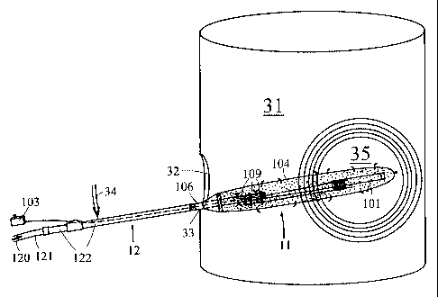
FIG. 3 now depicts the usage of this fully assembled on-line cleaning device,
to clean a
fuel burning facility 31 such as a boiler, furnace, scrubber, incinerator,
etc., and indeed any
CA 02384334 2002-03-07
WO 01/20239 PCT/US99/20568
13
fuel-burning or refuse-burning device for which cleaning by explosives is
suitable. Once the
cleaning device has been assembled as discussed in connection with FIG. 2, the
flow 120 of
liquid or gaseous coolant through hose 121 is commenced. As the coolant passes
through
coolant supply tube 122 and coolant delivery pipe 106, it emerges from coolant
apertures 109 to
fill cooling envelope 104 and provide a flow of coolant (e.g. water or air) to
surround explosive
device 101, maintaining explosive device 101 at a relatively cool temperature.
By way of
example, not limitation, optimal flow rates for water range between
approximately 20 and 80
gallons per minute, and for air, between approximately 5 to 10 cubic feet per
minute at 10 to 90
psi, depending on the ambient temperature to be protected against.
Once this liquid or gas flow is established and explosive device 101 is
maintained in a
cool state, the entire cooling and cleaning delivery assembly 11 is placed
into on-line facility 31
through an entry port 32 such as a manway, handway, portal, or other similar
means of entry,
while coolant supply and explosive positioning system 12 remains outside of
said facility. At a
location near where assembly 11 meets system 12, coolant delivery pipe 106 or
coolant supply
tube 122 is rested against the bottom of entry port 32 proximate the point
designated by 33.
Because a liquid coolant pumped through cooling envelope 104 introduces a fair
amount of
weight into assembly 11 (with some weight also added to system 12), a downward
force
designated by 34 is exerted to system 12, with point 33 acting as the fulcrum.
Applying
appropriate force 34 and using 33 as the fulcrum, the operator moves and
positions explosive
2 0 device 101 freely through on-line facility 31 to the position desired. It
is further possible to
place a fulcrum fitting device (not shown) at location 33, so as to provide a
stable fulcrum and
also protect the bottom of port 32 from the significant weight pressure
exerted at the fulcrum.
Throughout this time, new (cooler) coolant is constantly flowing into the
system while older
(hotter) coolant which has been heated by the on-line facility exits via
semipermeable cooling
2 5 envelope 104 and / or release valve 130, so that a continuous flow of
coolant into the system
maintains explosive device 101 in a cool state. For gaseous coolant, the added
weight
introduced by a fluid coolant as discussed above is not an issue. Finally,
when the operator has
moved explosive device 101 in the desired position, initiator 103 is activated
to initiate the
explosion. This explosion creates a shock wave in region 35, which thereby
cleans and deslags
3 0 that region of the boiler or similar facility, while the boiler / facility
is still hot and on-line.
As used herein, "envelope and explosive positioning means" shall be
interpreted to refer
to whatever means might be apparent to and employed by someone of ordinary
skill to move
cooling envelope 104 and the cooled explosive device 101 therein through on-
line facility 31
CA 02384334 2002-03-07
WO 01/20239 PCT/US99/20568
14
and into position for at will detonation. As disclosed above, the "envelope
and explosive
positioning means" comprises drawing elements 12, 106, and 112, but it is to
be clearly
understood that many other configurations for this envelope and explosive
positioning means
may occur to and be used by someone of ordinary skill fully within the scope
of this disclosure
and its associated claims.
Referring back to FIG. 2, during the explosion, explosive device 101,
detonator cap
102, cap wire 119, broomstick 112, and broomstick attachment means 113 are all
destroyed by
the explosion, as is cooling envelope 104. Thus, it is preferable to fabricate
broomstick 112 out
of wood or some other material that is extremely inexpensive and disposable
after a single use.
Similarly, cooling envelope 104, which is for a single use only, should be
fabricated from a
material that is inexpensive, yet durable enough to maintain physical
integrity while fluid or gas
is being pumped into it under pressure. And of course, cooling envelope 104
must enable a
continuous flow of coolant, and so, for example, should be semi-permeable
(105) or contain
some other suitable means such as release valve 130 that enable a continuous
supply of cool
coolant to enter proximate explosive device 101 as hotter coolant exits.
Semipermeability 105
can be achieved, for example, by using any appropriate membrane which in
essence acts as a
filter, either with a limited number of macroscopic puncture holes, or a large
number of fine,
microscopic holes. Release valve 130 may be any suitable air or fluid release
valve known in
the art, and again, may be used in addition to or in place of semipermeability
105.
2 0 On the other hand, all other components, particularly coolant delivery
pipe 106 and all
of its components 107, 108, 109, 110, 111, and 118, as well as bolt 114 and
nut 115, are
reusable, and so should be designed from materials that provide proper
durability in the vicinity
of the explosion. (Again, note that the length of broomstick 112 determines
the distance of
coolant delivery pipe 106 and its said components from the explosion, and that
approximately
two feet or more is a desirable distance to impose between explosive device
101 and any said
component of coolant delivery pipe 106, to minimize explosive damage and shock
waves back
to the operator.)
Additionally, because liquid coolant filling cooling envelope 104 adds
significant weight
to the right of fulcrum 33 in FIG. 3, if the coolant to be used is a fluid,
the materials used to
3 0 construct cleaning delivery assembly 11 should be as lightweight as
possible so long as they can
endure both the heat of the furnace and the explosion (cooling envelope 104
should be as light
as possible yet resistant to any possible heat damage), while to
counterbalance the weight of 11,
coolant supply and explosive positioning system 12 may be constructed of
heavier materials,
CA 02384334 2002-03-07
WO 01/20239 PCT/US99/20568
and may optionally include added weight simply for ballast. Water weight can
also be
counterbalanced by lengthening system 12 so that force 34 can be applied
farther from fulcrum
33. And of course, although system 12 is shown here as embodying a single
coolant supply
tube 122, it is obvious that this assembly can also be designed to employ a
plurality of tubes
5 attached to one another, and can also be designed so as to telescope from a
shorter tube into a
longer tube. All such variations, and others that may be obvious to someone of
ordinary skill,
are fully contemplated by this disclosure and included within the scope of its
associated claims.
FIG. 4 depicts an alternative preferred embodiment of this invention with
reduced
coolant weight and enhanced control over coolant flow, and remote detonation.
10 In this alternative embodiment, detonator cap 102 now detonates explosive
device 101
by a remote control, wireless signal connection 401 sent from initiator 103 to
detonator cap
102. This eliminates the need for lead wire entry port 127 that was shown in
FIG. 1 on coolant
supply tube 122, as well as the need to run wire pairs 126, 118 and 119
through the system to
carry current from initiator 103 to detonator cap 102.
15 FIG. 4 further shows a modified embodiment of cooling envelope 104, which
is
narrower where coolant first enters from coolant delivery pipe 106 and wider
in region 402 of
explosive device 101. Additionally, this cooling envelope is impermeable in
the region where
coolant first enters coolant delivery pipe 106, and permeable (105) only in
the region near
explosive device 101. This modification achieves two results.
2 0 First, since a main object of this invention is to cool explosive device
101 so that it can
be introduced into an on-line fuel-burning facility, it is desirable to make
the region of cooling
envelope 104 where explosive device 101 is not present as narrow as possible,
thus reducing the
water weight in this region and making it easier to achieve a proper weight
balance about
fulcrum 33, as discussed in connection with FIG. 3. Similarly, by broadening
cooling envelope
104 near explosive device 101, as shown by 402, a greater volume of coolant
will reside in
precisely the area that it is needed to cool explosive device 101, thus
enhancing cooling
efficiency. This modification is particularly pertinent to fluid cooling,
where fluid weight is an
issue.
Second, since it desirable for hotter coolant that has been in the modified
cooling
3 0 envelope 104 of FIG. 4 for a period of time to leave the system in favor
of cooler coolant being
newly introduced into this envelope, the impermeability of the entry region
and midsection of
cooling envelope 104 enables all newly-introduced coolant to reach explosive
device 101 before
that coolant is allowed to exit cooling envelope 104 from its permeable (105)
section 402.
CA 02384334 2002-03-07
WO 01/20239 PCT/US99/20568
16
Similarly, coolant in the permeable region of cooling envelope 104 will
typically have been in
the envelope longest, and will therefore be the hottest. Hence, the hotter
coolant leaving the
system is precisely the coolant that should be leaving, while the cooler
coolant cannot exit the
system until it has traveled through the entire system and thus become hotter
and therefore ready
to leave. This essential result is also achieved when release valve 130 is
placed proximate the
end of cooling envelope 104 that envelopes explosive device 101, as
illustrated, since coolant
will have traveled all the way through the system by the time it exits. It is
to be noted that the
modified embodiment of FIG. 4 is pertinent to both liquid and gas cooling.
Because the essential objective of the invention disclosed herein is to permit
explosive
device 101 to be moved through and freely positioned within a hot, online heat
exchange device
31 without premature detonation, and then detonated at will, alternative
preferred embodiments
are also feasible which dispense with or supplement the liquid or gaseous
coolants described
above, in favor of using heat-resistant materials to cool the explosive and
thereby protect the
explosive from premature detonation.
Along these lines, FIG. 5 illustrates an alternative embodiment using one or
more
highly-heat-resistant insulating materials to insulate explosive device 101
and detonator cap 102,
in place of or in addition to the aforementioned liquid or gaseous coolants,
thereby maintain
explosive device 101 such that it remains cooled and does not detonate
prematurely. In this
embodiment, most aspects of FIGS. 1 through 4 remain fully intact. However, in
this
embodiment, cooling envelope 104 surrounding explosive device 101 and
detonator cap
102 comprises a flame retardant, high heat-resistant material. This embodiment
of cooling
envelope 104 maintains a sufficiently cool ambient temperature inside envelope
104 to
protect against the heat of online heat-exchange device 31, thereby preventing
premature
discharge or degradation of explosive device 101. As with the earlier-
described
embodiments, cooling envelope 104 fits over explosive device 101 and detonator
cap 102,
and be sealed at the cooling envelope opening proximate 108. This can be
achieved simply
by using the threaded connection at 108 as earlier described, or
alternatively, but not
limiting, using high heat-resistant tape or other methods of fastening,
including wire or
high heat-resistant rope.
3 0 In its preferred embodiment, heat-resistant cooling envelope 104 of FIG. 5
comprises both an outer insulating layer 502 and an optional but preferred
inner insulating
layer 504 to maximize heat-resistant protection. Outer insulating layer 502
comprises at
least one layer of, for example, commercially-available knitted silica,
fiberglass and / or
CA 02384334 2002-03-07
WO 01/20239 PCT/US99/20568
17
ceramic cloth, including, but not limited to: knitted (or unknitted) silica
cloth, aluminized
silica cloth, silicone coated silica cloth, fiberglass cloth, silicone
impregnated fiberglass
fabric, vermiculite coated fiberglass, neoprene coated fiberglass, ceramic
knitted (or
unknitted) cloth and/or silica glass yarns knitted into a cloth. The silica,
fiberglass and/or
ceramic fabrics or cloths may be treated or untreated. Such cloths or fabrics
may be
treated with vermiculite or neoprene or any other flame retardant and heat-
resistant
chemical or material to increase the insulating factor of the cloth. In
addition, there are
cloths in the marketplace made of silica, fiberglass and/or ceramic which are
treated with
processes for which the treatments are proprietary and / or have not been
publicly
1 o disclosed. Combinations using more than one of the aforementioned
insulators are also
suitable, and are considered within the scope of this disclosure and its
associated claims.
Optional but preferred inner insulating layer 504 comprises a suitably-
reflective
material, for example, aluminum foil (aluminized) cloth. Inner insulating
layer 504 is
oriented to reflects outward, away from explosive device 101 and detonator cap
102, any
heat that penetrates outer insulating layer 502. Inner insulating layer 504
can be
independent of, but within, inner insulating layer 502, or it can be attached
directly to the
inner side of outer insulating layer 502. Other suitable materials for inner
insulating layer
504 include, but are not limited to, silica cloth, fiberglass cloth, ceramic
cloth, and / or
stainless steel cloth. Various combinations of more than one of the above
cloths are possible as
2 0 well. For example, not limitation, fiberglass or silica cloths can be
aluminized, thus resulting in
an aluminized fiberglass cloth or an aluminized silica cloth. And any or all
of the cloths
mentioned above, separately or in combination, can be treated in various
proprietary and non-
proprietary ways known in the art.
Cooling envelope 104 in this embodiment is preferably cylindrical, fitting
over
explosive device 101 and detonator cap 102, just as in the earlier
embodiments. The open
end of cooling envelope 104 may be preattached to screw threads as illustrated
in FIG. 2,
or may be pre-sewn closed or closed by using any heat-resistant material such
as high heat
resistant tape, wire or heat-resistant rope. Once this embodiment of cooling
envelope 104
is slipped over explosive device 101 and detonator cap 102, the open end of
the tube is
3 0 closed by the methods described above.
Detonator cap 102 continues to be detonated as described above, using any of
electronic, non-electronic (e.g., shock / percussion and heat-sensitive
detonation), or remote
control means. For electronic detonation, another consideration in this
embodiment is the
CA 02384334 2002-03-07
WO 01/20239 PCT/US99/20568
18
insulation of the wire 118, 119, 126 which is connected to detonator cap 102.
This wire
118, 119, 126 is run inside coolant delivery pipe 106 as in the earlier
embodiments, or may be
run outside of this pipe. Coolant delivery pipe 106 in the present embodiment
in fact does
not need to deliver any coolant (unless this embodiment is combined with the
earlier,
coolant-utilizing embodiments of FIGS. 1 through 4), and so need not comprise
coolant
apertures 109. But in any event, it is preferred to use an insulated high heat-
resistant wire.
Such wire products are commercially available. If additional insulation of the
wire is
needed, the wire may be further insulated using high heat-resistant tape, and
/or one of the
heat-resistant materials mentioned above for outer insulating layer 502 may be
wrapped
around such wire.
If additional insulation is needed against extremely high heat environments,
this
embodiment of cooling envelope 104 may also be filled with optional non-
flammable bulk
fiber insulation 506. The preferred material for bulk fiber insulation 506 is
an amorphous
silica fiber, however, other suitable materials which may be used for this
purpose include
any of the materials mentioned earlier as suitable for outer insulating layer
502; however,
for use as insulation 506, these materials are preferably not woven into a
cloth, but are
used in a bulk, fibrous form.
This embodiment achieves an insulating factor of more than two-thousand
degrees
Fahrenheit (2000~F), and the insulation materials themselves have a melting
temperature in
excess of three-thousand degrees Fahrenheit (3000~F).
This embodiment may be used in a wide variety of heated environments. The
temperature at which explosive device 101 detonates will dictate the number of
insulating
layers, types, and thickness of the insulting materials that are used. These
factors
determine the amount of insulation need to protect explosive device 101 and
detonator cap
102 in the environment in which they are placed. Because cooling envelope 104
is
destroyed with each explosion, it is desirable to use only those insulating
layers and
materials which are essential for any given heat environment, so as to
minimize the cost of
materials used for this single-use cooling envelope 104.
It is important to emphasize that while the embodiment of FIG. 5 can stand
alone, it
3 0 may also be used in combination with the embodiment of FIGS. 1 through 4.
That is, the
embodiment of FIG. 5 may be combined with fluid or air coolants, as described
above, by
providing cooling envelope 104 with permeations 105 and / or release valve 130
as earlier
shown and described, or it can stand alone without coolants.
CA 02384334 2002-03-07
WO 01/20239 PCT/US99/20568
19
In the event that the embodiment of FIG. 5 used standing alone, all that needs
to
change from the embodiments of FIGS. 1 through 4 is that liquid or gas coolant
need not
be supplied, and that cooling envelope 104 must be insulted as described
above. The
various pipes and conduits 122, 106 need not be -- but still may be --
hollowed so as to
carry liquid or gas, and coolant delivery pipe 106 need not -- but still may --
comprise
coolant apertures 109. Fluid weight is not an issue when FIG. 5 is used as a
stand-alone
embodiment, since no fluid is involved. The assembled apparatus is introduced
into,
moved freely through, and used in connection with online heat exchange device
31, precisely
as earlier described in connection with FIG. 3.
FIG. 6 illustrates an alternative preferred embodiment wherein explosive
device 101 is
itself prepared to be highly heat-resistive, so it can be used for deslagging
in place of or in
addition to the aforementioned liquid or gaseous coolants, and / or the
aforementioned highly-
heat-resistant insulating cooling envelope 104, in any desired combination.
In this embodiment, neither the liquid nor gaseous coolant of FIGS. 1 through
4, nor the
insulated cooling envelope 104 of FIG. 5, is required. Rather, explosive
device 101,
detonator cap 102, and cap wire pair 119 (if any wire is used) are constructed
to be self-
insulating and thereby self cooling. The preferred explosive material 606 used
inside of
explosive device 101 is a pliable explosive emoltion, but other suitable
materials may also
be used within the scope of this disclosure and its associated claims. This
emoltion is
2 o injected into and encased within a heat-resistant explosive casing 602
made from or insulted
by at least one layer of one or more of the various heat-resistant fabrics and
cloths
described above in connection with FIG. 5 (e.g. silica cloth, aluminized
silica cloth,
silicone coated silica cloth, fiberglass cloth, silicone impregnated
fiberglass cloth,
vermiculite coated fiberglass, neoprene coated fiberglass, ceramic cloth
and/or silica glass
yarns knitted into a cloth, including the various treatments mentioned above).
In a
preferred variation of this embodiment, such heat-resistant material replaces
the traditional
outside plastic or paper product explosive casing which holds explosive
material 606. In an
alternative variation, this explosive casing 602 is wrapped around, and simply
insulates, a
non-heat-resistant traditional plastic or paper product explosive casing 608.
Traditional
3 0 explosive casing 608 is shown in dashed lines since it is omitted entirely
in the preferred
variation of this embodiment.
Explosive device 101 explosive casing 602 also comprises a detonator well 604
sufficiently removed from the outside surface of explosive device 101 and
explosive casing
CA 02384334 2002-03-07
WO 01/20239 PCT/US99/20568
602 such that detonator cap 102, when placed into said detonator well 604,
will be suitably
insulted. Preferably, detonator well 604 is located substantially proximate
the center of
explosive casing 602, as illustrated. This allows detonator cap 102 to be
inserted in the
center of the explosive charge and thereby maximally insulated. As in the
previous
5 embodiments, detonator cap 102 is detonated by electronic, non-electronic or
remote
control means.
Once detonator cap 102 is inserted into detonator well 604 of explosive device
101,
the end may be sealed using high heat-resistant tape at 610. Any exposed wires
such as
119 may be insulated or re-insulated using high heat-resistant tape. Another
method of
10 insulating wires such as 119 is to cover these wires using insulating
fabric tubing such as
silica or fiberglass tubing, or silicone coated fiberglass or silicone tubing.
Indeed, the
insulting fabrics discussed in connection with outer insulating layer 502 of
FIG. 5 may all
be applied with equal facility to insulating any and all detonating wires.
For additional heat tolerance, the explosive device 101 and detonator cap 102
of this
15 embodiment may be cooled or even frozen before insertion into online heat-
exchange device
31. Various methods of retaining the cold temperature following this cooling
may be used
at a job site including packing explosive device 101 and detonator cap 102 in
dry ice or
keeping such them in a refrigerator or freezer equipment.
This embodiment may also be used standing alone, or in combination with any of
20 the other embodiments of FIGS. 1 through 5. That is, the high heat-
resistant explosive
device 101 of FIG. 6 may be further insulated by using the heat-resistant
jacket as
described in FIG. 5, and / or may be further protected using one of the
cooling methods
described in connection with FIGS. 1 through 4. It is also to be noted that
the explosive
device 101 of FIG. 6 can be used in any environment where it is desirable to
have a
controlled detonation of explosives within a hot surrounding environment.
Because it is possible to utilize the embodiments disclosed herein separately
or in
combination with one another, any cooling envelope 104 that supplies a liquid
or gas
coolant will be referred to herein as a "coolant-supplying" envelope, any
cooling envelope
104 that is insulated 502, 504, 506 will be referred to herein as an
"insulating" envelope,
3 0 and any cooling envelope 104 that comprises explosive casing 602 will be
referred to
herein as a "casing" envelope. Thus, for example, not limitation, if a number
of the
embodiments disclosed herein were to be used in combination, one might for
example,
simultaneously employ three cooling envelopes 104 such that a casing envelope
104, 602
CA 02384334 2002-03-07
WO 01/20239 PCT/US99/20568
21
encases explosive material 606 and comprises explosive device 101, such that
an insulating
envelope 104, 502, 504, 506 surrounds and further insulates casing envelope
104, 602, and
such that a coolant-supplying envelope 104, with semipermeability 105 and / or
valve 130
in turn surrounds and delivers liquid and / or gaseous coolant to insulating
envelope 104,
502, 504, 506.
While many variations will occur to someone of ordinary skill based on general
knowledge of the field as well as the prior disclosures herein, when this
embodiment is used
standing alone, all that is really necessary is to attach the explosive device
101 of FIG. 6 to a
longer embodiment of a "broomstick" such as 112, using any suitable explosive-
to-
broomstick attachment means 113 such as, but not limited to, duct tape, wire,
rope, or any
other means that provides a secure attachment. (See the discussion of this
attachment in
connection with FIG. 2.) An elongated broomstick 112, or any other pole
configuration that
might occur to someone of ordinary skill, is then used to move explosive
device 101 into, and
freely through, online heat exchange device 31. Explosive device 101 is then
detonated at will,
again, as earlier described in connection with FIG. 3.
While the disclosure thus far has discussed several preferred embodiments, it
will be
obvious to someone of ordinary skill that there are many alternative
embodiments for achieving
the result of the disclosed invention. For example, although an envelope /
stick configuration
and a single explosive device was discussed here, any other geometric
configuration of
2 0 explosives, including a plurality of explosive devices, and / or including
the introduction of
various delay timing features as among such a plurality of explosive devices,
is also
contemplated within the scope of this disclosure and its associated claims.
This would include,
for example, the various explosive configurations such as those disclosed in
the various U.S.
Patents earlier-cited herein, wherein these explosive configurations are
provided a similar means
by which a coolant can be delivered to the explosive, or the explosive can be
suitably heat
insulted, in such a way as to permit on-line detonation. In short, it is
contemplated that the
delivery of coolant to one or more explosive devices by any means obvious to
someone of
ordinary skill, enabling those explosive devices to be introduced into an on-
line fuel-burning
facility and then simultaneously or serially detonated in a controlled manner,
is contemplated by
3 0 this disclosure and covered within the scope of its associated claims.
It is to be understood that the terms "cool" and "cooling" are to be broadly
interpreted,
recognizing that the key object of this invention is to maintain the explosive
in a sufficiently
cool state prior to the desired time of detonation so that it does not
prematurely detonate, and to
CA 02384334 2002-03-07
WO 01/20239 PCT/US99/20568
22
allow this cooled explosive to be moved through online heat exchange device 31
to any desired
detonation position prior to detonation at will. Thus, "cool" and "cooling" as
interpreted
herein, in the various embodiments, is achieved through several alternate
approaches, namely:
using liquid coolant, using gaseous coolant, using suitable insulation to
surround the explosive
device, and / or fabricating the explosive device itself so as to be self
insulating and self
cooling. In the embodiments utilizing insulation, the insulation is in fact
maintaining the
explosive in a cooler state than it would otherwise be in absent the
insulation, and is thus
serving to "cool," or is "cooling," the explosive within the scope of this
disclosure and its
associated claims, and within the fair meaning of the words "cool" and
"cooling" as commonly
understood, even through it may not be actively providing a cooling medium as
do the coolant
embodiments of this invention. In short, "cool" and "cooling" are to be
understood as
encompassing both active cooling, and insulating to preventing the
overheating, of explosive
device 101.
Further, while only certain preferred features of the invention have been
illustrated and
described, many modifications, changes and substitutions will occur to those
skilled in the art.
It is, therefore, to be understood that the appended claims are intended to
cover all such
modifications and changes as fall within the true spirit of the invention.