Note: Descriptions are shown in the official language in which they were submitted.
CA 02384588 2002-03-11
WO 01/19679 PCT/US00/24904
FLEXIBLE TISSUE HANDLING APPARATUS
This invention relates to handling items such as stacks or clips of
facial tissues and more particularly to configuring such clips for cartoning
such
as for placement into particular cartons.
In the past, such tissues are produced in select count stacks or
"clips" comprising one flat tissue lying atop another in an elongated flat
shaped stack being generally longer than it is wide. This configuration is
okay
for flat shaped carton packaging; the clip is simply pushed endwise from a
cartoner bucket into the box. Typically, the box has at least one major panel
generally parallel with the tissues and an opening in the panel provides
access
for tissue removal for use. On the other hand, upright, cubic or boutique
cartons are more confining. The clip must be bent into a U-shape and thusly
configured, pushed sideways into the boutique carton which appears more like
a cube than the rectangular shape of the flat carton. In these boutique
CA 02384588 2002-03-11
WO 01/19679 PCT/US00/24904
-2-
cartons, a major panel adjacent the bend in the confined clip is provided
with an opening for accessing the tissues for withdrawal and use.
In the past, when changing a product line or output from a
flat carton to a boutique carton, there were two options. A first option was
for the manufacturer to simply purchase two cartoning machines. One
would handle a flat pack or cartoning process and another would handle a
boutique or upright cartoning process. Of course, this involved the cost of
an extra machine.
Alternately, if a single machine was used to produce filled
flat cartons and boutique cartons, the machine would be stopped and
many changeover parts added to reconfigure the machine to render it
operable for properly configuring the clip for the new carton. This resulted
in production downtime and significant expense for changeover parts.
More particularly, it will be appreciated that when filling flat
cartons, flat clips are simply pushed longwise into the carton through an
open end of the carton. End flaps are then closed to produce a finished
carton or tissue box. When boutique or upright cartons are used,
however, the clips are bent into a U-shape which is then pushed sideways
into an open-sided boutique carton, which is then closed to produce a
finished boutique carton or tissue box.
CA 02384588 2002-03-11
WO 01/19679 PCT/US00/24904
-3-
Generally, the clips in either case are received in individual
buckets of a bucket conveyor, and, in appropriate configuration, are
loaded into cartons moving along a machine direction, in phased relation
to the buckets. A transfer guide bucket conveyor is typically interposed
between the first mentioned buckets and the cartons for receiving and
guiding the configured clip as it is pushed transversely from the bucket into
the carton.
It will be appreciated from this description that the respective
clips must be oriented in the buckets for transfer into the cartons in two
different directions. For elongated flat clips, their elongated dimension
should lie transversely across the buckets, perpendicular to the machine
direction of the bucket conveyor, for endwise motion transversely across
the bucket, toward and into the flat cartons. For boutique configured, U-
shape clips, which are moved sideways transversely off the buckets into the
boutique cartons, their elongated dimension should lie parallel to the
machine direction of the bucket conveyor as they are moved into the
cartoner. Thus, the clips for flat cartons are oriented longitudinally at 90
degrees to the longitudinal position of the clips configured for boutique
cartons.
CA 02384588 2002-03-11
WO 01/19679 PCT/US00/24904
-4-
Accordingly, any machine which is changed over to handle
both type clips or cartons must be provided with a variety of parts to
produce proper clip orientation and handling, essentially for conveying
boutique configured clips with their elongated dimension parallel to the
machine direction or flat configured clips at 90 degrees or perpendicular to
the machine direction.
Accordingly, it has been one objective of the invention to
provide a single, improved tissue handling apparatus and methods for
tissue clips of varied configuration.
It has been a further objective of the invention to produce an
improved handling apparatus and methods for tissue cartoning which
handles both flat and boutique configured clips, but without extensive
downtime and with a minimum number of change parts.
It has been a further objective of the invention to provide
improved apparatus and methods for turning tissue clips for proper
orientation for insertion into flat cartons and for selectively transporting
tissue clips for loading into boutique cartons.
It has been a further objective of the invention to provide
improved methods and apparatus for handling differently configured tissue
clips on the same handling apparatus with only minimal changeover parts.
CA 02384588 2002-03-11
WO 01/19679 PCT/US00/24904
-5-
To these ends, a preferred embodiment of the invention
contemplates use of a bucket conveyor wherein the buckets have a floor
and a transverse channel disposed in the floor. The channel has a length
which extends in a direction across the floor and a width which is wider
than the side-to-side width of the clips, but shorter than the length of the
clips. According to the invention, all clips of whatever final configuration
they may assume, are fed into the buckets with their elongated length
oriented in a downstream direction parallel to the machine direction of the
buckets. In this position, the clips span over the transverse channels in the
respective buckets.
When it is desired to fill flat cartons with a flat clip, the clip is
turned so that it extends across the bucket parallel to the transverse
channel . This turning causes the flat clip to fall into the channel. From
there, it can then be pushed transversely and endwise into a flat carton.
When it is desired to fill a boutique or upright carton, the clip
is maintained in its original position spanning the channel, its length being
longer than the channel is wide. A tamp or confiner is moved in over the
clip and pushes an intermediate portion of the clip down into the channel
into a U-shaped configuration with a central portion of the clip at least
partially down in the channels and outer ends contacted by the bucket
CA 02384588 2002-03-11
WO 01/19679 PCTIUSOO/24904
-6-
floor or the channel walls and being directed upwardly. From this position,
the U-shaped clip may now be pushed transversely and sideways out of
the bucket and into a boutique or upright carton.
In both cases, a preferred embodiment of the invention
provides a transfer guide bucket conveyor between the transport bucket
and the carton to confine or guide the traversing clip into a carton in
appropriate configuration.
One difficultly in accomplishing the turning process of the
flat clip so it falls into the channel is potential loss of control, allowing
the
clip to scramble, twist or otherwise diverge from its uniform stacked
configuration. In order to turn and drop the clip and maintain it in
appropriate alignment at the same time, the preferred embodiment of the
invention contemplates two offset opposed pushers engaging side edges of
the flat clip at offset longitudinal positions to carefully turn it and allow
it to
drop. The pushers may comprise plates extendable transversely into the
buckets from opposite sides, and into and above the transverse channels.
Ends of the pushers engage and twist or turn the clip. Once in alignment
with the channel, the clips are aligned with internal facing sides of the
pushers which configure and guide the clip through its fall into the channel.
CA 02384588 2002-03-11
WO 01/19679 PCTIUSOO/24904
-7-
Thereafter, the pushers are retracted and the clips are
conveyed downstream to a cartoner where they can be pushed endwise
transversely across the buckets, along the channels and into a flat carton.
The channels are slightly wider than the side-to-side width of the clip so
there is room for each pusher between a respective side of the clip and the
adjacent channel wall.
The pushers thus control the flat clip edges, maintaining
alignment of the tissues in the clip as they are turned into final position
and
drop into the channel for end loading. After turning and aligning the clip,
the pushers are retracted and the buckets continue downstream in a
machine direction, maintaining the position or condition of the clips for
loading into cartons.
The pushers are preferably independently carried on barrel
loader-like apparatus disposed on opposite sides of the bucket conveyor
and are, of course, either stopped or disabled when it is desired to
configure the clips for loading boutique cartons where the clips are not
turned. No change parts are required for selectively turning or not turning
the clips.
When the clips are conveyed downstream to the loading
station of a cartoner, the clips are pushed transversely and endways into
CA 02384588 2002-03-11
WO 01/19679 PCT/US00/24904
-8-
flat cartons from the buckets and through the transfer guide buckets, flat
confiners or tamps descend over the clips to compress and hold them.
When the clips are configured in U-shape for loading into boutique
cartons, these flat confiners are changed out for narrow elongated tamps or
confiners descending into the U-shaped clip's center to configure confine
and hold it while it is pushed transversely out of the bucket through the
transfer guide bucket and into the boutique carton by, for example, a
synchronized barrel loader. This constitutes only minimal changeover
parts which can be fitted and released, as desired, by quick coupling
mechanisms, thus reducing or eliminating any significant downtime.
In a further aspect of the invention, its particular application
to tissue cartons as described, the pitch of the flat cartons may vary from
that of the boutique cartons. This is accommodated by using independent
servo drives for the bucket conveyors and transfer guide conveyors on the
one hand and the carton conveyor on the other. Where both of the
diverse pitches are accommodated in a standard cartoner machine pitch
of, for example, 12 inches, it is only necessary to use one independent
servo drive to appropriately phase the relative position of the carton
conveyor and the bucket conveyor and associated barrel loader.
CA 02384588 2002-03-11
WO 01/19679 PCTIUSOO/24904
-9-
Accordingly, the invention provides a flexible, dual function
improved tissue handling apparatus for easily configuring tissue clips for
flat or boutique cartoning.
These and other objectives and results will be readily
appreciated from the following detailed description of a preferred
embodiment of the invention and from the drawings in which:
Fig. 1 is an expanded view of the load configuration of a
tissue clip for a boutique carton;
Fig. 2 is an expanded view of the load configuration of a
tissue clip for a flat carton;
Fig. 3 is a plan view of a tissue handling apparatus
according to a preferred embodiment of the invention and shown together
with upstream and downstream components of an entire system for
loading clips into cartons;
Fig. 4 is an enlarged plan view in more detail of that portion
of a tissue handling apparatus shown at the right hand area of Fig. 3;
Fig. 4A is an illustrative end view taken along lines 4A-4A of
Fig. 4;
Fig. 5 is a side view of a clip receiving and turning bucket
according to the invention and showing in phantom a clip before turning;
CA 02384588 2002-03-11
WO 01/19679 PCTIUSOO/24904
-10-
Fig. 5A is a view similar to Fig. 5, but showing a turned flat
clip;
Fig. 6 is a plan view taken along lines 6-6 of Fig. 5;
Fig. 7 is an end view taken along lines 7-7 of Fig. 5;
Fig. 8 is an illustrative operational view of the turning and
dropping of a clip into a bucket channel according to the invention;
Fig. 9 is an illustrative plan view of loading flat configured
clips from buckets, through transfer buckets, into flat cartons;
Fig. 9A is an illustrative side view taken along lines 9A-9A
of Fig. 9;
Fig. 9B is an illustrative side view taken along lines 9B-9B
of Fig. 9;
Fig. 10 is an illustrative plan view of loading boutique
configured clips from buckets through transfer guide buckets into boutique
cartons;
Fig. 10A is an illustrative side view taken along lines 10A-
10A of Fig. 10;
Fig. 10B is an illustrative side view taken along lines lOB-
lOB of Fig. 10;
Fig. 11 is a load end view of a transfer bucket;
CA 02384588 2002-03-11
WO 01/19679 PCT/US00/24904
-11-
Fig. 11A is a top plan view of the transfer bucket of Fig. 11
shown in place between a carton and a bucket; and
Fig. 11B is a side view of the transfer bucket and adjacent
components of Fig. 11B.
Turning now to the drawings, there is illustrated therein
methods and apparatus for handling both a flat tissue clip configuration
and an upright, cubic or boutique tissue clip configuration. Typically,
tissues such as facial tissues are packed in flat or conventional shaped
cartons. Alternately, tissue clips are bent or formed into a U-shape and
these are packed in upright, cubic or boutique shaped cartons.
It will be appreciated that, while the invention described
herein is particularly useful for handling clips in these alternate
configurations, the invention and its principles can be found useful in
handling or transporting other products or items having varying shapes or
configurations.
Turning now to Figs. 1 and 2, there is illustrated therein the
orientation of clips of facial tissues both in a respective boutique clip
configuration and in a flat clip configuration.
Fig. 1 illustrates the load orientation for a boutique clip
configuration. In Fig. 1, an upright cubic or boutique carton 10 is
CA 02384588 2002-03-11
WO 01/19679 PCT/US00/24904
-12-
illustrated, having a tissue opening 11 in a major panel which is situated in
this view on the bottom of the carton 10. A boutique clip 12 is illustrated
in its boutique configuration, such that the clip itself takes on a bent or U-
shaped configuration for loading into the carton 10.
It will be appreciated that the clip has a width 13 and a
foreshortened length from end-to-end due to the bending of the tissues in
the clip, but generally running from the narrow edge of one tissue through
the clip to its narrow opposed and parallel edge. Such a clip 12 is inserted
into the carton 10 by means of a longitudinal U-shaped pusher 14 moving
in a load direction 15 as will be described. The clips are preferably loaded
on the move while they are being transported in a downstream or machine
direction MD with the cartons 10 and the pusher 14 moving in the same
downstream direction at the same time such that the pusher 14 is also
moving transversely in the load direction to push the clips into the carton
10.
Illustrated in Fig. 2 is a carton of flat shaped or configuration
18. Carton 18 is also provided with a tissue opening 19 disposed in what
is shown in Fig. 2 as a major bottom panel of the carton. A flat clip 20
comprising a plurality of facial tissues has narrow ends 21, 22, each
defining across them a width 23, and the clip is elongated between ends
CA 02384588 2002-03-11
WO 01/19679 PCT/USOO/24904
-13-
21, 22, defining a length 24. A U-shaped pusher 14 is moved in a load
direction 15 to push the flat clip 20 endwise and transversely into the
carton 18. This is accomplished while the clip 20, the carton 18 and the
pusher 14 are also moving in a downstream direction.
It will be appreciated with respect to both Figs. 1 and 2 that
the cartons are conveyed in a downstream direction by a carton conveyor,
such as a lug type conveyor, while the pushers 14 are conveyed
sequentially in a downstream direction, one after the other, by means of a
well known barrel loader which is useful to convey the pushers in a
downstream or machine direction while, at the same time, causing the
pushers to extend transversely to load the clips into the cartons
respectively.
At the same time, the clips are carried in the separate
buckets of a bucket conveyor (not shown in these figures) in the machine
direction. As will be described, the clips are pushed from these buckets
transversely through transfer guide buckets (not shown in Figs. 1, 2) and
into the cartons 10 and 18 respectively.
For illustration purposes, a complete system for loading
individual clips which are discharged in any conventional manner, such as
from a log saw 28, is illustrated in Fig. 3. The system shown in Fig. 3
CA 02384588 2002-03-11
WO 01/19679 PCT/US00/24904
-14-
includes a log saw discharging clips onto a clip conveyor 29 from where
the clips are introduced into a spacing apparatus including a turnwheel 30
having depending clip pushing pins 31 for engaging the rear end of the
clips and moving the clips in a curved path, as shown in this embodiment
as a 90 degree turn, into a clip handling apparatus 35, as will be described
in more particular detail herein.
When the clips are discharged from the wheel 30, they are
deposited into buckets on a bucket conveyor 36, as also will be described
in more detail. The clips can be deposited on the bucket conveyor 36 in
any known fashion and by any apparatus which does not comprise a part
of this particular invention. The clips may be fed onto the ends of the
buckets or pushed onto them in that manner, or may be fed from an
overhead position and dropped into the buckets. In any event, it will be
appreciated that, at this point, all of the clips, whether to be formed in a
boutique configuration or in a flat configuration are, in fact, flat and
elongated in a machine direction MD as they reside on the buckets of the
bucket conveyor 36 at this position.
From the clip handling apparatus 35, the clips are conveyed
in the buckets to a cartoning apparatus for moving the clips from the full
bucket conveyors into respective cartons. This cartoner is illustrated at 38
CA 02384588 2002-03-11
WO 01/19679 PCT/US00/24904
-15-
and includes carton feeding and erecting apparatus 39, a carton conveyor
40, a transfer guide bucket conveyor 41 and downstream carton handling
apparatus including dust flap closing, gluing, flap closing, compression and
other conveying apparatus for finishing the carton and feeding it to a
product discharge end 43 of the cartoner, where the respective cartons
either of the boutique style 10 or the flat style 18 are discharged for
packaging and shipment. The cartoner 38 includes a barrel loader 32 of
typical configuration including a cam track 34 for moving pushers to load
cartons as will be described. Also, at the cartoner, a carousel 33 is
disposed above bucket conveyor 36 and transfer guide conveyor 41 as will
be described.
The handling apparatus 35 of the invention is best seen in
the right hand area of Fig. 3 which appears in enlarged format in Fig. 4.
In Fig. 4, it will be appreciated that a plurality of clips are sequentially
transported by the bucket conveyor 36 into the clip handling apparatus 35.
At this point, it will be instructive to note that the clips C are all
elongated
and in flat configuration, having a longitudinal dimension moving in the
same direction and in parallel with the machine direction MD of the bucket
conveyor 36. In this configuration, the clips all span transverse channels
(described below) in the buckets.
CA 02384588 2002-03-11
WO 01/19679 PCTIUSOO/24904
-16-
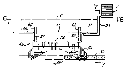
Turning now momentarily to Figs. 5-7, the individual
buckets of the bucket conveyor 36 will be described. The individual
buckets 46, as perhaps best seen in Fig. 5, include a bucket floor
comprising a rearward transverse floor surface 47 and a forward transverse
floor surface 48. A channel 49 is disposed in the floor defined by surfaces
47, 48 and comprises channel walls 50, 51 and channel floor 52. As
shown in Fig. 5, channel floor 52 is depressed or lower than the floor
surface 47, 48 of the bucket 46.
Each bucket is provided with a clip pusher 53 extending
above the floor surface 47 at the trailing edge of the bucket. The bucket is
mounted on two carrying brackets 54, 55 which are provided with
provisions for securing the buckets to parallel conveyor chains which
comprise the bucket conveyor 36. Each of the buckets is centered on the
chains at a desired pitch of, for example, twelve inches.
Further, it will be appreciated that the bucket channel 49 has
a predetermined width illustrated at 57 and a predetermined transverse
length indicated at 58. The length 58 of the channel 49 is somewhat
longer than the length 24 of the flat clips C. At the same time, it will be
appreciated that the width 57 of channel 49 between the walls 50, 51 is
somewhat wider or greater than the width 23 of the clips C and, as well,
CA 02384588 2002-03-11
WO 01/19679 PCT/USOO/24904
-17-
the widths 13 and 23 of the flat clips, as shown in the various figures.
Moreover, the width 57 of channel 49 is significantly shorter than the
length 24 of any flat clip as deposited on the bucket in the machine
direction MD.
Accordingly, when a flat clip C is placed onto the bucket 46,
such a clip C being shown in phantom in Figs. 5 and 6, it will be
appreciated that the clip spans the channel 49 with the forward and trailing
ends of the longitudinal dimension of the clip being supported respectively
on the floor surfaces 48 and 47 of the bucket 46.
It will be appreciated that in this configuration, the
longitudinal dimension extending between the short ends 21, 22 of the
clip is arranged parallel to the machine direction and motion of the buckets
in the bucket conveyor 36 as they move through the apparatus. Thus, as
initially introduced to the buckets 46 on bucket conveyor 36, the clips are
moving downstream in machine direction but in an orientation which is 90
degrees off from that desired for eventual loading of flat clips onto flat
cartons.
Specifically and as noted above, it is most desirable to insert
the clips endwise into flat cartons 20. Since the clips are initially moved
lengthwise in a downstream direction, however, it is necessary to turn them
CA 02384588 2002-03-11
WO 01/19679 PCT/US00/24904
-18-
90 degrees so that they can be pushed transversely out of the buckets in an
endwise direction at the cartoner to load flat cartons 20.
In order to accommodate this reorientation of the clips C, or
clip 20 in this case, where a flat configuration is desired for filling a flat
carton 18, the buckets 46 according to the invention are provided with the
channels 49. When the clips are turned 90 degrees, they drop into the
channel 49 from where they can now be moved transversely in an endwise
direction into an appropriate downstream carton 18 as will be further
described.
In order to turn the clips, apparatus such as that illustrated in
Figs. 4, 4A and 8 is provided according to the invention. In particular, the
handling apparatus 35 as shown in Fig. 4 is provided with a plurality of
transversely movable and offset pushers, such as pushers 60-60D on one
side of the bucket conveyor 36 and pushers 62-62D on the other side of
bucket conveyor 36.
Each of the pushers 60, 62 and their similar pushers, are
mounted on respective barrel loader-like apparatus 64, 66, including cams
68, 70 operationally disposed on opposite sides of bucket conveyor 36.
Each of the pushers is carried on a carriage, such as that illustrated in Fig.
4, mounted on slides and a cam follower is disposed on each of the
CA 02384588 2002-03-11
WO 01/19679 PCT/US00/24904
-19-
carriages and is operable to move the slides in a perpendicular direction
with respect to the machine direction MD to carry the pushers across the
bucket conveyor 36 as will be described.
It will be further appreciated that the pushers 60, 62 and
their downstream similar elements are offset in the machine direction MD,
one from the other. Accordingly, it will be appreciated that pusher 60
leads pusher 62, pusher 60A leads pusher 62A, pusher 60B leads pusher
62B, pusher 60C leads pusher 62C and pusher 60D leads pusher 62D.
Thus, it will be appreciated that the pushers 60 are offset in a downstream
direction from the pushers 62.
As seen in Fig. 4, it will be appreciated that as the pushers
are extended by the respective cams 68, 70, they engage the clips C (20)
at positions which are offset with respect to the direction machine
direction. The offset forces on longitudinally displaced locations on
opposite sides of the clips C serve to twist or turn the clips so that the
clips
slide across the floor surfaces 47, 48 respectively of the buckets 46 until
the
clips are reoriented 90 degrees, such as that position shown between
pushers 60B and 62B in Fig. 4.
In this condition, the clips fall freely from bucket floor
surfaces 47, 48 into the channels 49 and channel floors 52 of each of the
CA 02384588 2002-03-11
WO 01/19679 PCT/USOO/24904
-20-
individual buckets on which the clips are being carried. At the same time,
it will be appreciated from Fig. 4A that the respective pushers 60, 62 are
of such a height and shape that the pushers extend down into the channel
49, but also above the channels.
As noted above, the channel is sufficiently wide, front to
back, that it can accommodate not only the clip lying therein, but the
relatively thin width of each of the extended pushers 60, 62, one lying on
each side of the clip between the clip and the respective adjacent channel
wall, 50, 51 respectively.
This orientation of the pushers 60, 62 is shown in phantom
in Figs. 5 and 5A and also in Fig. 6 where the pushers are withdrawn.
This orientation is also illustrated in Fig. 8 as will be appreciated.
After the clips have been turned and dropped into the
respective channels 49, continued downstream motion causes the barrel
loader-like apparatus 64, 66 to withdraw the respective pushers as
0
illustrated in Fig. 4. The clips thereafter are conveyed in a downstream
direction in an aligned fashion, centered in the channels 49 of the buckets
46.
It will be appreciated that the pushers 60, 62 serve, not only
to turn the clips, but to control the clips during this turning and during
their
CA 02384588 2002-03-11
WO 01/19679 PCT/USOO/24904
-21-
dropping into the channel 49 so that the clips are maintained in an aligned
and uniform condition. The flat sided pushers engage and control the
sides of the clip as it drops and lands on the channel floor 52.
It should also be appreciated that it is not necessary for the
pushers to move into the channels 49. For example, in an alternate
embodiment, the pushers 60, 62 may extend across the buckets 46
generally at the level of floor surfaces 47, 48 but not below into the
channels. In such a case, the front-to-back channel width between walls
50, 51 is selected more closely to the width of clips 20. In this case, the
clip sides are first engaged by the pusher ends, then their respective
internal opposed surfaces, then the channel walls 50, 51 to maintain their
alignment in the channels.
Moreover, it will be appreciated that as the pushers engage
the opposite sides of the clips C or 20, they have a centering effect on the
clips so that the end result is that the clips are positioned within the
bucket
channels 49 so that their ends do not overhang either of the edges of the
buckets 46.
Of course, it is not desirable to turn the clips C when those
clips will be eventually configured into a U-shaped boutique configuration
for packaging in a boutique carton 10. Accordingly, when the machine is
CA 02384588 2002-03-11
WO 01/19679 PCT/US00/24904
-22-
selectively set up to handle clips in a boutique configuration, the barrel
loader-like apparatus on either side of the bucket conveyor 36 is switched
so that the cam followers of the carriages for the pushers 60, 62 are
directed into a straight direction (MD) track which does not taper toward
the bucket conveyor 36. Thus, the pushers are rendered inactive and do
not turn the clips on the buckets. Instead, the clips are simply conveyed
downstream, with their longitudinal dimension moving along with and
parallel to the machine direction MD.
Alternately, or in addition, the bucket loader-like pusher
apparatus 64, 66 can simply be stopped, this being accommodated, for
example, by an independent drive, and it will be appreciated that the
bucket loader-like pushers are independently mounted and driven with
respect to the bucket conveyor 36.
It will also be appreciated that the respective clips C may be
one height when it is desired to eventually configure those clips into a
boutique configuration, such as boutique clip 12 and another height when
they are to be configured into a flat clip configuration, such as flat clip
20.
Accordingly, it will be appreciated that as used herein, the
letter C is used to refer to clips generically, however those clips will be
later
configured, while the number 20 refers to the flat clips which will be
CA 02384588 2002-03-11
WO 01/19679 PCT/USOO/24904
-23-
configured and packaged in that manner and the number 12 is used to
referred to clips which are or will be configured in a bent or boutique clip
configuration for packaging in a boutique carton 10.
The sequence of operation described above in terms of
turning a clip 20 is further seen in the illustrative plan view of Fig. 8. In
that figure, it will be appreciated that a clip 20 is carried on the floor
surfaces 47, 48 of a bucket 46 spanning the channel 49. When the clips
are carried by the buckets, they are pushed by the dogs or pushers 53 as
illustrated at the bucket 46A in Fig. 8. Floor surfaces 47, 48 are in a plan
disposed above that of channel floor 52.
The downstream bucket has moved to a position where the
barrel loader-like apparatus has engaged the pushers 60, 62 to move
inwardly into the channel 49 across the buckets 46, and engage the clip
20, thereby turning or rotating it in the direction of the arrow 71. As
shown with respect to the bucket 46C in Fig. 8, the pushers 60, 62 have
been fully extended into the channel 49 and across the bucket 46C,
allowing positioning and fully turning the clip 20 a rotation of 90 degrees
from its position as shown in bucket 46A where the clip 20 is dropped into
the channel. The clip 20 is dropped into the channe149 of the bucket 46C
onto floor 52.
CA 02384588 2002-03-11
WO 01/19679 PCTIUSOO/24904
-24-
Thereafter in a further downstream position with respect to
bucket 46D, the pushers 60, 62 have been withdrawn, leaving the clip
centered and aligned in the channel 49 for further handling and packaging.
As noted above, this turning operation would be omitted in
the case of clips C which are to be configured in a boutique or bent
configuration. Those clips simply remain in position as does the clip 20 as
shown in bucket 46A, the pushers 60, 62 having been disabled.
Turning now to Figs. 9 and 10, there is illustrated therein a
further packaging of the clips into the respective cartons at the cartoner 38.
Cartoner 38 includes a carton feeder 39, such as flat carton feeder FCF,
for feeding cartons onto a carton conveyor 40, the lugs of which are
illustrated respectively in Figs. 9 and 10 as lug sets 44, 45.
As shown in Fig. 9, lug sets 44 engage erected flat cartons
18 and moves them in the downstream direction or machine direction.
Fig. 9 will be described in this connection as illustrating the loading of the
flat cartons 18 with flat clips 20.
It will be appreciated that the cartoner 38 also includes a
transfer bucket conveyor 41 having a plurality of transfer buckets 75. This
transfer bucket conveyor 41 is elongated in the machine direction and is
interposed between bucket conveyor 36 and carton conveyor 40. The
CA 02384588 2002-03-11
WO 01/19679 PCTIUSOO/24904
-25-
construction of these buckets 75 is perhaps best seen in Figs. 11, 11A and
11B. Each transfer bucket has two opposed sidewalls, 76, 77 which
converge toward a discharge end 78 from a wider receiving end 79. Each
of the buckets 75 are mounted on two brackets 80, 81 comprising the
guide of the transfer guide bucket conveyor 41.
It will be appreciated that the guide bucket conveyor 41 as
disposed in the cartoner apparatus 38 has only a limited operational run,
as diagrammatically indicated in Fig. 3. This transfer guide bucket
conveyor is disposed between the carton conveyor 40 on the one side and
the guide bucket conveyor 36 on the other, so that clips which are pushed
from the guide bucket conveyor 36 are moved transversely through the
guide buckets 75 and into the cartons 18.
In this regard, it will be appreciated that the bucket channels
49 are indexed and aligned with the transfer guide buckets 75 and that the
floors 52 of the buckets 46 are in preferably the same plane as the floors
82 of the transfer guide bucket 75.
It will also be appreciated that the carton conveyor 40 is
provided in a standard or other desirable pitch such as twelve inches,
however, it will be appreciated that that pitch is defined by, for example,
the lug sets 44, with the lug sets 45 being disposed within that pitch. In
CA 02384588 2002-03-11
WO 01/19679 PCT/US00/24904
-26-
any event, the bottom panel of the carton is disposed in about the same
plan and level as the floors 82 of the transfer bucket 75 and 52 of channel
49 of buckets 46, and in any event significantly lower than bucket floor
surfaces 47, 48.
It will also be appreciated that the lug sets 45 are on a similar
pitch with respect to each other, but that the distances between the lug sets
44 and 45 respectively may vary, one to accommodate one particular
width of a flat carton 18, for example, and the other to accommodate the
particular leading to trailing edge width of a boutique carton 10, for
example, as will be described in connection with Fig. 10.
Accordingly, it will be appreciated that the bucket conveyor
36 and the transfer bucket conveyor 41 are driven by drives which are
controlled by independent servo drives with respect to the carton conveyor
40 so that the appropriate phase alignment can be made when the
machine is selectively switched from handling flat clips, such as clips 20 for
example, to boutique configured clips, such as clips 12.
Also, it will be appreciated that the loading of the clips 20
into the cartons 18 as shown in Fig. 9 is accomplished by a conventional
barrel loader 32 (not shown in detail) having disposed on the ends of its
pushers a U-shaped pusher 14. This pusher moves in a load direction 15
CA 02384588 2002-03-11
WO 01/19679 PCT/US00/24904
-27-
to push the clips 20 from the floors 52 of the channels 49 through the
transfer guide buckets 75, across their floors 82 and into the cartons 18 as
illustrated in Fig. 9.
Thereafter, the barrel loader 32 withdraws the pushers 14
and the filled cartons 18 are moved downstream for flap gluing, closing,
and other finishing steps and discharge.
It will be appreciated that the clips 20 are preferably
compressed as they enter the cartoner 38 and are prepped for transport
into the cartons. Flat confiners or tampers 85 are shown in this regard.
For example, in Fig. 9A, a confiner or tamp 85 which may be mounted on
an overhead carouse133, for example, descends via means of a cam
driven track, for example, onto the clip 20, confining and compressing it in
the channel 49.
This confiner 85 may be elongated so that it extends along
the full length of the clip lying transversely across the bucket 46. This
confiner may also extend into or over the guide bucket 75 as illustrated in
Fig. 9B, however, the confiner 85 stops short in a transverse direction
from the cartons 18. Thereafter, the confiners 85 are lifted upwardly and
away, where they are moved through a return run and back toward an
entry end of the cartoner 38.
CA 02384588 2002-03-11
WO 01/19679 PCTIUSOO/24904
-28-
Accordingly, Fig. 9A illustrates a confiner which is moved
downwardly and which also continues to move in machine direction MD
to compress and confine the flat clip 20 before and while it is being pushed
with the U-shaped pusher 14 which does not interfere with the confiner 85
transversely through the transfer bucket conveyor 75 and into the carton
18.
Fig. 9B illustrates the continuing influence of the confiner 85
on the clip 20 as it is pushed through the guide bucket 75 and into the
carton 18.
Turning now to Fig. 10, it will be appreciated that this figure
illustrates the packaging of a clip 10 in a boutique carton or container 10
by first configuring the clip into a boutique shaped clip 12. In Fig. 10 it
will be appreciated that a boutique carton feeder (BCF) has fed cartons 10
onto the carton conveyor 40, the cartons 10 being driven by the sets of
carton conveying lugs 45 at an appropriate pitch, and that the transfer
guide bucket conveyor 41 and the bucket conveyor 36 has been phased
by means of an appropriate servo drive into appropriate registry with the
cartons 10, all of which move downstream and in a machine direction.
Of course, it would be possible to provide a line drive
machine, where the various phases are mechanically adjusted, however,
CA 02384588 2002-03-11
WO 01/19679 PCT/US00/24904
-29-
the servo drive mechanisms for the various conveyors have been found to
easily produce the phase registries that are required between the
components.
As shown in Fig. 10, the clip 12 lies or spans across and
overthe channel 49 and is supported by the surfaces 47, 48 of the buckets
46. An elongated confiner or tamp 86, which has been substituted for
tamp 85, is utilized to initiate and hold the clip 12 in a U-shaped
configuration partially at least down into channel 49. Confiner 86 is not as
wide in the machine direction as confiner 85 and, when moved
downwardly as illustrated in Fig. 10A, pushes the clip downwardly into the
channel 49 of the bucket 46, so that the clip takes on a U-shaped
configuration. This shape may be more steeply inclined than as shown in
Fig. 10A when tamp 86 compresses the bight of the clip 12.
As the side of clip 12 is engaged by the U-shaped pusher 14,
the clip is pushed transversely out of the channel in a load direction 15 into
the transfer guide buckets 75, the floors of which are preferably co-planar
with the floors 52 of the bucket channels 49.
The confiners or tamps 86 are elongated so they extend over
the transfer guide bucket 75 and the confiners are carried on the horizontally
moving carousel 33 described above, for example, with the confiners being
CA 02384588 2002-03-11
WO 01/19679 PCTIUSOO/24904
-30-
raised and lowered by an appropriate cam track, just as the confiners 85 with
respect to Fig. 9. The confiners extend laterally or transversely in a load
direction 15 into the area of the transfer guide buckets 75 and thus hold and
maintain the clips 12 in a U-shaped configuration, somewhat pressing the
bight or intermediate portion of the clip into the channel 49 and into the
respective guide buckets 75 as the clip is pushed.
The inwardly tapered walls 77, 76 of the transfer guide buckets
serve to further confine and shape the boutique clips 12 into the appropriate
final configuration for loading into the cartons 10 as illustrated
CA 02384588 2002-03-11
WO 01/19679 PCT/US00/24904
-31-
as the buckets 46, the containers 10 and the guide buckets 75 move from right
to left as shown in this figure.
The pushers 14 are mounted on and actuated by a barrel loader
of any conventional design, such that the pushers 14 are moved in a load
direction 15 as shown in Fig. 10, transversely of the buckets 46 and the
transfer guide buckets 75 to push the clips into the boutique cartons 10 in a
bent or U-shaped configuration.
Accordingly, it will be appreciated that the clips 12 are urged
downwardly and at least partially into the channels 49 to provide and
accommodate their boutique configuration for loading into the cartons 10.
Thereafter, the barrel loader withdraws the pusher 14 and the confiners 86 are
raised, both to operate through return runs for further engagement, as the
machine continues in operation.
In an alternative embodiment for boutique clip handling and
loading, it will be appreciated that a manufacturer might desire to load the
clips upside down from the configuration described above. In other words,
the curved intermediate portion or the bight is up, while the clip ends are
directed down.
In such a case, the apparatus described above is modified with a
device placed in the channel floor 52 of buckets 46 to selectively raise the
CA 02384588 2002-03-11
WO 01/19679 PCT/US00/24904
-32-
bight portion of the clip. Instead of tamp 86, a C-shaped tamp is used to
press
the ends of the clip downwardly toward the bucket 46 as it is compressed and
pushed sideways through transfer buckets and into a boutique carton.
Accordingly, it will be appreciated that the clip handling
apparatus 35, as particularly illustrated in Fig. 4, for example, renders the
entire tissue cartoning process viable for handling both flat carton tissue
clips
and boutique carton clip configurations with minimal equipment changeover
such as, for example, the changeover between the confiners 85 and 86 by
means of any quick releasable interconnecting means.
Moreover, it will be appreciated that the tissue handling
apparatus as illustrated in Fig. 4 provides positive control over the tissue
clips
which are to be turned, centering them in the bucket channels and dropping
them into the channels while maintaining them in an aligned format.
The clips cannot be over-rotated by virtue of the speed of the
turning operation, since they are held and confined by the pushers 60, 62
during the turning operation and as the clips are dropped into the channels.
Moreover, it will be appreciated that the pushers 60, 62 are
easily deactivated when it is desired to leave the clips moving with
longitudinal
dimensions headed downstream when, for example, the clips are to be
configured in a boutique configuration.
CA 02384588 2002-03-11
WO 01/19679 PCTIUSOO/24904
-33-
Accordingly, it is not necessary for the packager to purchase two
machines, one for flat carton clip handling and one for boutique carton clip
handling, nor is it necessary for the packager to acquire a machine which
requires numerous and expensive changeover parts and significant downtime,
when it is desired to selectively change from one clip configuration to the
other.
These and other objectives and advantages will become readily
apparent to those of ordinary skill in the art, without departing from the
scope
of the invention, and applicant intends to be bound only by the claims
appended hereto.
WE CLAIM: