Note: Descriptions are shown in the official language in which they were submitted.
CA 02384617 2002-03-11
WO 00/15525 PCT/AU99/00747
BULK HANDLING APPARATUS
TECHNICAL FIELD
This invention relates to bulk handling apparatus and in particular to storage
apparatus for storing bulk granular materials.
BACKGROUND ART
Bulk granular materials are typically stored in silos or large sheds. Silos
are
mostly utilised for storing grain and reclaiming is achieved through a base
cone
arranged coincident with the repose angle of the grain such that all material
will feed
gravitationally to a central outlet for discharge from the silo. A
disadvantage of this
arrangement is that such silos are relatively high and this necessitates
additional cost
and complexity for equipment to feed grain into the silos.
Mined bulk granular material is often stored in sheds where it may be
deposited, for example, by a central conveyor supported in the apex of a
conventional portal frame shed. Reclaiming of the product is achieved using
front
end loaders charging dump hoppers travelling over an outtold conveyor which
may
be arranged in a tunnel and fed from a central point. Capital cost of such
designs are
very high and large land areas are required for such storage. Additionally,
there is an
ongoing reclaiming cost necessitated by the use of supervised machinery to
reclaim
the material from the shed.
A further disadvantage of these systems is that many bulk solids have
properties that will allow the forming of ratholing and make those materials
bridge
over an out-loading point thereby stopping the exit flow of materials. The
problem of
bridging and ratholing may become extreme. in cases where material has been in
static storage for a considerable period of time thereby having allowed
gravitational
pressures to cause settlement or compaction of what may have been a relatively
freeflowing material.
Hydroscopic properties of some materials will allow them to become sticky in
storage adding further to the problems of extracting such material from silo
type
storage.
Mined bulk granular material is also stored as open stockpiles serviced by
rail
mounted stacker reclaiming machinery. Disadvantages of such systems include
the
CA 02384617 2002-03-11
WO 00/15525 PCT/AU99/00747
2
high cost of stockpiling and management with regard to the environment and
high
maintenance costs of the necessary equipment for stockpiling and reclaiming.
The present invention aims to alleviate at least one of the above
disadvantages and to provide storage apparatus which will be reliable and
efficient in
use.
DISCLOSURE OF INVENTION
With the foregoing and other objects in view, this invention in one aspect
resides broadly in storage apparatus suitable for storing granular material
and
including:-
a storage container;
a material inlet at the top of the storage container;
a material outlet at the base of the storage container, and
height adjustable levelling apparatus for levelling the upper surface of
material
contained in the container. Thus the upper surface may be levelled to enable
the
container to be filled to capacity when filling, and when discharging to level
the upper
surface to ensure complete discharge of material as the container is emptied
from
the base.
The levelling apparatus could be any suitable form of conveying apparatus
which conveys the material being fed into the container towards the outside of
the
container when filling and when emptying which conveys the material remaining
about the periphery of the container towards the centre for gravitational
discharge at
the base.
In a preferred embodiment, the levelling apparatus is in the form of a driven
rotary scraper rotatable about a vertical axis and having an overall diameter
substantially equal to the inside diameter of the container, the scraper
having blades
thereon engageable with the upper surface of material in the container so as
to move
the engaged material selectively inwardly or outwardly as required. For this
purpose,
the blades may be fixed or adjustable and the wheel may be reversible to
control the
direction of feed of the granular material. Alternatively, the vanes may be
reversible
or the scraper may include alternate sets which maybe lowered for engagement
with
the granular material.
CA 02384617 2002-03-11
WO 00/15525 PCT/AU99/00747
3
Preferably the rotary scraper includes an outer ring frame supported on
vertically adjustable mountings on or adjacent the container wall. It is also
preferred
that for best mechanical advantage, the drive apparatus for selectively
rotating the
wheel are mounted on the vertically adjustable mountings and drive the outer
ring
frame. The drive motor may drive a pinion engaged with an annular rack on the
ring
frame. Alternatively, the rotary scraper may be supported from a central
column and
driven therefrom. However this would impose complexities and high loads due to
the
need to transmit high operating torque through the column to an inner ring of
the
rotary scraper.
This invention may also be applied to reclaiming material from an unsupported
pile. Thus according to another aspect this invention resides broadly in a
method of
and apparatus for reclaiming material from a stockpile of granular material
including:
providing height adjustable spreading apparatus for spreading material from
the upper surface of the stockpile outwardly for passage to the base of the
stockpile;
providing reclaiming apparatus at the base of the stockpile, and
operating the spreading apparatus to cause feeding of that material in the
stockpile which does not initially flow gravitationally to the reclaiming
apparatus
toward the base of the remaining stockpile to enable feeding of substantially
all the material in the stockpile to the reclaiming apparatus. The stockpile
may be
supported on a base pad containing the reclaiming apparatus and, if desired,
the
stockpile may be contained within a peripheral wall.
The reclaiming method and apparatus of this invention may be used to
advantage with conventional silos and constitutes a further invention.
BRIEF DESCRIPTION OF THE DRAWINGS
In order that this invention may be more readily understood and put into
practical effect, reference will now be made to the accompanying drawings
which
illustrate a typical embodiment of the present invention and wherein:-
FIG. 1 is a side view of a storage facility made in accordance with one aspect
of this invention and shown partly cut-away;
FIG. 2 is a plan view of one form of a rotary scraper assembly;
FIG. 3 is a part sectional view showing the upper loading details of the
container;
FIG. 4 illustrates the peripheral support mechanism for the rotary scraper;
CA 02384617 2002-03-11
WO 00/15525 PCT/AU99/00747
4
FIG. 5 illustrates an alternate form of peripheral reclaiming apparatus for
reclaiming material from the storage container;
FIG. 6 is a cut-away side view of an alternate form of storage facility
utilising a
central material discharge;
FIG. 7 corresponds to Fig. 6 but illustrates a further discharge arrangement ;
FIG. 8 diagrammatically illustrates one form of friction drive for rotating
the
rotary scraper;
FIG. 9 diagrammatically illustrates an alternate form of friction drive; and
FIGS 10 and 11 illustrate the rotary scraper support and slide arrangement in
plan and side views respectively.
MODES FOR CARRYING OUT THE INVENTION
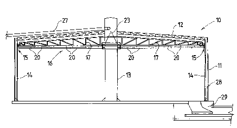
The storage apparatus 10 is in the form of a low profile container 11 having a
low pitched roof 12 supported by a the container wall 23 and centrally by a
large
diameter central column 13. A series of guide post assemblies 14 are arranged
vertically about the inside periphery of the container 11 and rotary support
apparatus
15 are engaged with the post assemblies 14 for vertical movement along the
posts
and support of the peripheral edge of the rotary scraper 16. The material is
introduced over a spreading cone 23 from a feed conveyor 27 and discharged
from a
peripheral reclaiming chamber 29 adjacent the side wall 28.
In the illustrated embodiment, the container is an eighty metre diameter
container with a wall height of about twenty metres and is adapted to contain
about
80,000 tons of mined or manufactured granular material, such as bauxite or map
dap
fertiliser.
The rotary scraper 16 illustrated in Fig. 2 has a series of radial arms 17
which
extend from an inner annular hub 18 to an outer annular rim 19 which support
scraper blades 20 in a suitable arrangement thereon. The blades 20 extend
downwardly from the underside of the arms 17 so as to engage the top surface
of
material contained in the container 11.
As illustrated in Fig. 4, the outer rim 19 includes an angle section member 21
having a vertical web which provides radial location against the centring
rollers 24
supported by the rotary support apparatus 15 and a horizontal web 25 providing
vertical support on the horizontal centring rollers 26. Both the rollers 24
and 26 are
CA 02384617 2002-03-11
WO 00/15525 PCT/AU99/00747
arranged for free rotation about their respective axes and are supported on
each
support apparatus 15.
The inner face of the vertical web 22 is also formed as an annular gear which
meshes with a driven gear 30 mounted directly on the output shaft of a
5 motor/gearbox assembly 31 mounted on the rotary support apparatus 15. In
order to
resist the torque applied to the support apparatus 15 by the drive motor 31,
each
guide post assembly 14 includes spaced apart posts between which the support
apparatus 15 engages. Each support apparatus 15 is suspended from the upper
edge of the container by a remotely operated hoist, all of which are operated
simultaneously so that the rotary scraper 16 can be raised and lowered to a
selected
position.
The inner hub 18 rotates freely about the central column 13 which extends
upwardly to provide an equipment deck 35 adjacent the roof and upwardly
therebeyond to support the roof and to support the discharge chute and upper
end of
the loading conveyor 37. If desired, a transfer conveyor 38 may also be
supported to
take the product to an adjacent storage facility once the container is full. A
flap valve
40 is provided for directing the flow either to the transfer conveyor 38 or
the
discharge chute 36 for discharge upon a cone shaped spreader cap 41 from which
the granular material flows into the container.
As shown in Fig. 5, discharge from the base of the container 11 is achieved
through a reclaiming chamber 42 adjacent the sidewall 43 of the container 11.
A first
belt-type 45 conveyer transfers material falling through the inlet 44 to an
outloading
conveyor 46 which elevates the material to a desired delivery station.
The storage apparatus 60 illustrated in Fig 6 utilises a centrally arranged
auger 61 disposed within the central column structure 62 about which material
to be
stored is introduced via a distribution cone 63 adjacent the column structure
62. The
auger 61 has a center shaft 65 supported by bearings 66 at its ends, and where
so
dictated by engineering design at suitable intermediate positions along its
center
shaft 65. The bearings 66 allow the auger to rotate about its axis. The auger
61 is
belt or chain driven by an electric motor 67 which is positioned adjacent the
lower
bearing 66 for suitable maintenace or service access away from the discharge
port
68 at the base of the auger 61.
CA 02384617 2002-03-11
WO 00/15525 PCT/AU99/00747
6
The apparatus 70 illustrated in Fig. 7 is a variation on the aparatus 10 of
Fig.
1. In this form a reclaim tunnel 71 extends across the base of the container
72 so as
to be fed gravationally from opposed peripheral reclaim chambers 73. As in the
earlier embodinemts feed is introduced axially from an inload conveyor 75
which
dumps onto the apex 76 of the distribution cone 77 for even distribution
thereabout.
A conveyor 78 is supported in the tunnel 71 for transferring material fed
through the
chambers for discharde as required.
In use, in each of the above storage apparatus the feed distributed about the
distribution cone will tend to pile up around the central column. However
rotation of
the rotary scraper in one direction will engage the scraper blades with the
sloped
face of the piled material and feed it outwards until the sloped face is
levelled. The
rotary scraper is then raised to feed any further matrial supplied about the
column
toward walls of the container until to container is filled to the uppermost
level of the
rotary scraper.
When discharging material, gravity feed will initiall feed material to the
central
reclaiming station or the peripheral reclaiming station or stations. The
material which
remains, either against the walls in the case of a central discharge, or about
the
column in the case of peripheral discharge can then be fed toward the
respective
reclaiming station by lowering the rotary scraper to engage the top of the
remaining
material and rotating it in the reverse direction to feed material inward to
the column
for discharge, or in the same direction for feeding material to peripheral
discharge
stations. The rotary scraper may be lower to a position adjacent the floor so
that
practically all material is discharged.
Figs. 8 and 9 show alternate friction drives for peripherally driving the
rotary
scraper 100. In Fig 8, the top annular chord 80 of the rotary scraper 10 is
provided
with a drive flange 81 extending thereabout. A reversible friction drive wheel
82 is
engaged with the flange 81 for rotating the rotary craper 100.
The wheel 82 is driven from a motor 83 carried by a pivot bracket 84 mounted
on a slide plate 85 moveable along one of the peripheral guide post
assemblies. The
slide plate 85 also carries a lower reaction wheel 89 on a further pivot
bracket 86
which may be pivoted upwards by a selectively operable ram 87 and linkage 88
to
clamp the flange 81 between the friction wheel 82 and the reaction wheel 89 so
as to
regulate the driving force transferred to the rotary scraper. Thus the rotary
scraper
CA 02384617 2002-03-11
WO 00/15525 PCT/AU99/00747
7
may stall if undue loads are applied thereto such as by forcing the scraper
too deeply
into a pile of material to be levelled, without damaging the motor or drive.
In the arrangement illustrated in Fig. 9, each radial truss 90 from which the
scraper blades are suspended carries a round-section ring 91, 92 at the end of
its
upper and lower chords 93, 94. A friction driving wheel 95 engages a flange
mounted on the top ring 91 and a reaction wheel 96 supports the lower ring 92.
The
raction wheel is supported directly on the slide 97 while the drive wheel 95
extends
from a motor/gearbox assembly supported pivotally from the slide 97 and
adjustably
by the selectively operable ram 98 which is used to regulate the drivng force
applied
to the rotary scraper as described above.
The slide 97 as illustrated in Fig. 10 has opposed vertically extending angle
rails 103
which engage captively through slide blocks 101 about the diagonally arranged
square-section rails 102 which form the vertical chords of a composite post
assembly
105. Opposed pulley wheels 106 supported at the top of the slide 97 enable the
slides to be raised and lowered by hoist cables, not shown, which extend
between
the wheels 106 on the slide 97 and the wheels 110 supported at the top of the
post
105 and driven by an electric winching arrangement 111 for raising and
lowering the
slide. The vertical rails 102 are connected to the sidewall,shown dotted at
112,
through stand-off mounting brackets 113.
The winches used to raise and lower the rotary scraper are preferably
positioned atop the guide posts and spaced evenly about the periphery of the
container. Additional winches may be provided intermediate the guide posts if
desired and such as may be required for very large diameter containers where
there
may be a significant span between adjacent-posts. Alternatively multi-stage
pneumatic rams or the like may be used as the means to raise and lower the
rotary
scraper.
From the above it will be seen that the overall height of the container is
relatively low and this facilitates filling of the container. Furthermore the
use of a
spreader enables the container to be filled to capacity and completely
emptied, thus
effectively using the space for storage. In addition all processing is
achieved without
the need for supervised machinery such as front end loaders.
CA 02384617 2002-03-11
WO 00/15525 PCT/AU99/00747
8
FIG. 12 is a sectional view of a conventional silo 110 which utilises he
central
feed auger 111 of this invention for discharging the contents therefrom. In
this
embodiment the auger 111 extends the full depth of stored product.
FIG. 13 illustrates the central feed auger utilised only in the bottom or
conical section
18 of a conventional silo 115 as this may be all that is required to provide
assistance
for the material to exit the silo.
It will of course be realised that the above has been given only by way of
illustrative example of the invention and that all such modifications and
variations
thereto as would be apparent to persons skilled in the art are deemed to fall
within
the broad scope and ambit of the invention as is defined in the appended
claims.